Herunterladen Inhalt Inhalt Diese Seite drucken
Inhaltsverzeichnis

Werbung

Verfügbare Sprachen
  • DE

Verfügbare Sprachen

  • DEUTSCH, seite 34
Sony Corporation
CBK-VF01
(SYM)
4-265-156-01(1)
HD ELECTRONIC VIEWFINDER
CBK-VF01
このオペレーションマニュアルには、事故を防ぐための重要な注意事項と製品の取り扱いか
たを示してあります。このオペレーションマニュアルをよくお読みのうえ、製品を安全にお
使いください。お読みになったあとは、いつでも見られるところに必ず保管してください。
OPERATION MANUAL
[Japanese/English/French/German/Italian/Spanish/Chinese]
Printed in Japan
2011.01 32
1st Edition
©2011
電気製品は、安全のための注意事項を守らないと、
火災や人身事故になることがあります。

Werbung

Inhaltsverzeichnis
loading

Inhaltszusammenfassung für Sony CBK-VF01

  • Seite 1 HD ELECTRONIC VIEWFINDER CBK-VF01 電気製品は、安全のための注意事項を守らないと、 火災や人身事故になることがあります。 このオペレーションマニュアルには、事故を防ぐための重要な注意事項と製品の取り扱いか たを示してあります。このオペレーションマニュアルをよくお読みのうえ、製品を安全にお 使いください。お読みになったあとは、いつでも見られるところに必ず保管してください。 Sony Corporation OPERATION MANUAL [Japanese/English/French/German/Italian/Spanish/Chinese] CBK-VF01 Printed in Japan (SYM) 2011.01 32 1st Edition 4-265-156-01(1) ©2011...
  • Seite 2 日本語 安全のために 電気製品は、 安全のための注意事項を守らないと、 火災や感電 警告表示の意味 などにより死亡や大けがなど人身事故につながることがあり、 オペレーションマニュアルお 危険です。 よび製品では、次のような表 事故を防ぐために次のことを必ずお守りください。 示をしています。表示の内容 をよく理解してから本文をお 安全のための注意事項を守る 読みください。 4 ページの注意事項をよくお読みください。 定期点検をする この表示の注意事項を守らな いと、感電やその他の事故に 長期間安全に使用していただくために、 定期点検を実施するこ よりけがをしたり周辺の物品 とをおすすめします。 点検の内容や費用については、 ソニーの に損害を与えたりすることが サービス担当者または営業担当者にご相談ください。 あります。 故障したら使用を中止する 注意を促す記号 ソニーのサービス担当者、 または営業担当者にご連絡ください。 万一、異常が起きたら • 異常な音、におい、煙が出たら 行為を禁止する記号 1 カメラの電源を切る。 2 接続コードを抜く。 3 ソニーのサービス担当者、または営業担当者に修理を依頼...
  • Seite 3: Inhaltsverzeichnis

    目次 注意 ...................... 4 概要 ....................5 使用上のご注意 ................5 各部の名称と働き ................6 カメラに取り付ける ................. 8 位置を調整する ................8 角度を調整する ................9 視度と画面を調整する ..............9 VF 筒部/アイピース部を跳ね上げる ..........10 画面や内部( LCD 画面)をクリーニングする ....... 12 仕様 ....................12 目次...
  • Seite 4 分解しない、改造しない ビューファインダーを回 分解したり、改造したりする 転するときには手や指を と、感電の原因となります。 挟まない ビューファインダー内部の調整 ビューファインダーを回転する や点検を行う必要がある場合 とき、本体と VF アームの間に は、必ずソニーのサービス担当 手や指を挟み、けがの原因とな 者にご依頼ください。 ることがあります。 内部に水や異物を入れない 水や異物が入ると火災の原因と なります。 万一、水や異物が入ったとき は、すぐにカメラの電源を切 り、接続コードを抜いて、ソ ニーのサービス担当者または営 業担当者にご相談ください。 油煙、湯気、湿気、ほこ りの多い場所では設置 • 使 用しない 上記のような場所で設置・使用 すると、火災や感電の原因とな ります。 ビューファインダーの接 眼レンズを太陽に向けて 放置しない 太陽光が接眼レンズを通して ビューファインダー内部に焦点 を結び、火災の原因となること があります。 太陽や輝度の高い光源に レンズを向けてアイピー...
  • Seite 5: 使用上のご注意

    概要 使用上のご注意 HD エレクトロニックビューファインダー 使用場所について CBK-VF01 は、 3.5 型 LCD カラービューファ インダーです。 気温の低い場所で使用すると、電源投入直 本機には以下のような特長があります。 後、動解像度が低下します。 高解像度・広視覚野 高精細 LCD の採用により、水平解像度 LCD (液晶)パネルの輝点・滅点 500TV 本以上の高解像度を実現しています。 について 大画面 LCD 搭載により、アイピースをはず した状態での快適な撮影が可能です。 本機の LCD (液晶)パネルは有効画素 99.99% 以上の非常に精密度の高い技術で 安定した画像 作られていますが、画面上に黒い点が現れ LCD 画面では、画面の明るさが変化しても たり(画素欠け) 、常時点灯している輝点 ひずみに影響しないため安定した画像が得...
  • Seite 6: 各部の名称と働き

    接眼レンズについて 各部の名称と働き 本機の接眼レンズを太陽などの強い光に向 けないでください。 太陽光などの強い光がレンズによって集光 することにより、 LCD パネルの焼損や火災 の原因になるおそれがあります。 お手入れについて • 画面の表面からほこりを取り除くときは、 ブロアーを使用してください。 • 画面をクリーニングするときは、シン ナーなどの溶剤はいっさい使用しないで ください。 a コネクター カメラの VF 端子(角型)に接続します。 b スライドストッパー 本機をカメラに取り付けて左右にスライド させるとき、本機がカメラからはずれるの を防ぎます。 c アイカップ d 視度調整リング 画面の映像が最もはっきり見えるように、 このリングを回して視度を調整します。 e アイピース部 使用状況に応じて、跳ね上げたり、取りは ずしたりすることができます。 各部の名称と働き...
  • Seite 7 f VF 筒部 n MIRROR (反転)スイッチ 使用状況に応じて、跳ね上げたり、取りは VF 筒部を跳ね上げたり、回転させたりして ずしたりすることができます。 画像が左右または上下に反転しているとき に使用します。 g タリーランプ L/R :画像を左右に反転させる カメラの REC START ボタン、レンズの VTR OFF :画像を反転させない ボタン、またはリモートコントロールユ B/T :画像を上下に反転させる ニットの VTR ボタンを押して、記録が始ま o ビューファインダーケーブル ると点灯します。 異常発生時は、点滅して警告表示を行いま p マイクホルダー す。 h PEAKING (ピーキング調整)つまみ 時計方向に回すと、画面の映像の輪郭が強 調され、レンズのフォーカス合わせが容易...
  • Seite 8: カメラに取り付ける

    ビューファインダーコネクターをカ カメラに取り付ける メラの VF 端子(角型)に接続する。 VF 端子(角型) ビューファインダーを取り付けたあと、接眼レン ズを太陽に向けて放置しないでください。 太陽光が接眼レンズを通して焦点を結び、火災の 原因になることがあります。 ご注意 本機を取り付けるときは、以下の点にご注意くだ さい。 • 必ずカメラの電源をオフにしてから、ビュー ファインダーコネクターをカメラの VF 端子(角 型)に差し込んでください。電源がオンの状態 取りはずすには でコネクターを差し込むと、本機が正常に動作 しないことがあります。 取り付けと逆の手順で行います。ただし、 • ビューファインダーコネクターをカメラの VF 端 本機を取り付けシューから取りはずすとき 子(角型)の奥まで確実に差し込んでくださ い。コネクターが確実に接続されていないと、 に、スライドストッパーを引き上げてくだ 画像が乱れたり、タリーランプが正常に点灯し さい(手順 1 の図参照) 。 ないことがあります。 位置を調整する カメラの左右位置固定リングをゆる める。...
  • Seite 9: 角度を調整する

    角度を調整する 視度と画面を調整する 本機の角度を調整します。 視度を調整するには 視度調整リングを回して、画像がはっきり 見えるように調整します。 画像/文字表示を上下反転させる には 本機は、被写体側から見ることもできるよ うに 180 °回転します。 この場合、画面上の画像や文字表示の上下 が逆になります。 MIRROR スイッチを B/T にすると、画像や文 字表示の上下を反転させて、通常の状態に 戻すことができます。 視度調整リング 画面を調整するには 画面の状態を、次の項目について調整でき ます。 輪郭: PEAKING つまみで調整する。 濃淡: CONTRAST つまみで調整する。 明るさ: BRIGHT つまみで調整する。 1 PEAKING つまみ 2 CONTRAST つまみ 3 BRIGHT つまみ 視度と画面を調整する...
  • Seite 10: Vf 筒部/アイピース部を跳ね上げる

    跳ね上げるには VF 筒部/アイピース 底のクリップを押してはずし、上に開きま 部を跳ね上げる す。 120 °開いた位置でロックします。 VF 筒部/アイピース部を跳ね上げると、内 部の LCD 画面またはその鏡像を見ることが できます。 ここでは、 VF 筒部の跳ね上げ/取りはずし について説明します。アイピース部も同様 に跳ね上げたり、取りはずしたりすること ができます。 通常はロック位置で使用してください。 LCD 画面 ロック位置からさらに開くこともできます が、再度 120 °の位置でロックしたい場合 は、いったん元の閉じた位置まで戻してか ら開き直してください。 VF 筒部/アイピース部を跳ね上げる...
  • Seite 11 取りはずすには 画像/文字表示を左右反転させる には MIRROR スイッチを L/R にすると、画面上の 画像や文字表示の左右を反転させることが できます。 底のクリップを押してはずす。 VF 筒部を上げる。 上のボタンを VF 筒部と反対の方向に スライドさせてロックをはずす。 VF 筒部を水平にスライドさせて取り はずす。 VF 筒部/アイピース部を跳ね上げる...
  • Seite 12: 画面や内部( Lcd 画面)をクリーニングする

    画面や内部( LCD 画面) 仕様 をクリーニングする 一般 本機の画面や内部( LCD 画面)をクリーニ ングするときは、本機をカメラから取りは 電源 ずし、内部の部品を傷つけないように充分 DC10.5 ∼ 17.0 V (カメラから供給) 注意して行ってください。 消費電力 使用温度 ◆ 本機をカメラから取りはずす方法について 0 ℃∼+ 40 ℃ は、 「カメラに取り付ける」 ( 8 ページ)をご 保存温度 覧ください。 − 20 ℃∼+ 60 ℃ 質量 ◆ VF 筒部を取りはずす方法については、 「取り 約...
  • Seite 13 性能 輝度 ( typical ) 200 cd/m アイピース装着時 解像度 500 本以上 色温度 6500K ( typical ) 接続端子 角型 26 ピンコネクター 付属品 オペレーションマニュアル( 1 ) 別売品 ビューファインダー回転収納機構 BKW-401 関連製品 ソリッドステートメモリーカムコーダー 1 ) PMW-500 1) PMW-500 に取り付ける場合は、カムコーダー 側のバージョンが Ver. 1.10 以上であることが 必要です。 重要...
  • Seite 14 However, there is For the customers in Europe no guarantee that interference will not occur The manufacturer of this product is Sony in a particular installation. If this equipment Corporation, 1-7-1 Konan, Minato-ku, does cause harmful interference to radio or Tokyo, Japan.
  • Seite 15 Table of Contents Table of Contents Overview ..................... 16 Usage Notes....................16 Names and Functions of Parts ..............17 Attaching the Viewfinder to a Camera ............ 18 Adjusting the Position ..............19 Adjusting the Angle ................ 19 Adjusting the Focus and Image Display ..........20 Raising the Viewfinder Barrel and Eyepiece ..........
  • Seite 16: Overview

    Overview Usage Notes The CBK-VF01 HD Electronic Viewfinder is a Place of use 3.5-inch LCD color viewfinder. When using the viewfinder in low temperature This viewfinder has the following features: environments, dynamic resolution levels may High resolution and wide visual angle...
  • Seite 17: Names And Functions Of Parts

    Viewfinder lens Names and Functions of Do not leave the viewfinder lens facing toward a Parts strong light source, such as sunlight. Burnout of the LCD panel or fire may occur if the lens focuses the sunlight or other strong light source.
  • Seite 18: Attaching The Viewfinder To A Camera

    g Tally indicator Attaching the Viewfinder Lights up when recording is started by a press of the REC START button on the camera, the VTR to a Camera button on the lens, or the VTR button on the remote control unit. When an abnormality occurs, the tally indicator flashes to indicate a warning.
  • Seite 19: Detaching The Viewfinder

    Couple the viewfinder connector to the Adjusting the Angle VF connector (rectangular) on the camera. You can adjust the angle of the viewfinder. VF connector (rectangular) Reversing the display (image/text indication) vertically The viewfinder can be rotated as much as 180 degrees toward the direction facing the subject.
  • Seite 20: Adjusting The Focus And Image Display

    Adjusting the Focus and Raising the Viewfinder Image Display Barrel and Eyepiece You can view the LCD screen inside the Adjusting the focus viewfinder or its mirrored image by raising up the Turn the diopter adjustment ring until the image viewfinder barrel or the eyepiece.
  • Seite 21 Raising the viewfinder barrel Detaching the viewfinder barrel Push the clip on the bottom to release and flip up the viewfinder barrel. It locks at the 120-degree position. Normally use it in the locked position. Although you can open it farther from the lock position, once return it to the closed position to lock it at the 120-degree position again.
  • Seite 22: Cleaning The Lcd Screen And Interior

    Cleaning the LCD Screen Specifications and Interior General When cleaning the LCD screen or interior of the viewfinder, detach the viewfinder from the Power supply camera, detach the viewfinder barrel from the 10.5 to 17.0 V DC (supplied by the camera) body, and take care not to damage the Power consumption components.
  • Seite 23 Design and specifications are subject to change without notice. Note Always verify that the unit is operating properly before use. SONY WILL NOT BE LIABLE FOR DAMAGES OF ANY KIND INCLUDING, BUT NOT LIMITED TO, COMPENSATION OR REIMBURSEMENT ON ACCOUNT OF THE LOSS OF PRESENT...
  • Seite 24 E3 (urbain extérieur) et E4 (environnement EMC contrôlé, ex. studio de télévision). Pour les clients en Europe Le fabricant de ce produit est Sony Corporation, 1-7-1 Konan, Minato-ku, Tokyo, Japon. Le représentant autorisé pour EMC et la sécurité des produits est Sony Deutschland GmbH, Hedelfinger Strasse 61, 70327 Stuttgart, Allemagne.
  • Seite 25 Table des matières Présentation....................26 Remarques d’utilisation ................26 Nomenclature et fonctions des éléments ..........27 Fixation du viseur sur une caméra............29 Ajustement de la position..............29 Ajustement de l’angle ..............30 Ajustement de la mise au point et de l’affichage de l’image....30 Relèvement de l’oculaire et du barillet du viseur ........
  • Seite 26: Présentation

    Présentation Remarques d’utilisation Le viseur électronique HD CBK-VF01 est un Lieu d’utilisation viseur couleur LCD de 3,5 pouces. Lorsque vous utilisez le viseur dans des Ce viseur présente les caractéristiques suivantes : environnements à basse température, les niveaux Haute résolution et grand angle visuel de résolution dynamique peuvent diminuer...
  • Seite 27: Nomenclature Et Fonctions Des Éléments

    Objectif du viseur Nomenclature et Ne laissez pas l’objectif du viseur face à une fonctions des éléments source puissante de lumière, comme la lumière solaire. Il se peut que l’écran LCD grille ou qu’un incendie se produise si l’objectif concentre la lumière du soleil ou d’une autre source puissante de lumière.
  • Seite 28 f Barillet du viseur n Interrupteur MIRROR Relevez-le ou retirez-le lorsque la situation le L’affichage de l’image sur l’écran est inversé nécessite. horizontalement ou verticalement lorsque vous relevez ou tournez le barillet du viseur. Utilisez g Indicateur de signalisation cet interrupteur pour commander l’affichage de Cet indicateur s’allume lorsque l’enregistrement l’image dans de telles situations.
  • Seite 29: Fixation Du Viseur Sur Une Caméra

    Branchez la fiche du viseur dans le Fixation du viseur sur connecteur VF (rectangulaire) de la caméra. une caméra Connecteur VF (rectangulaire) ATTENTION Lorsque le viseur est fixé, ne laissez pas l’objectif du viseur en face du soleil. Les rayons du soleil directs peuvent entrer par l’objectif, se concentrer dans le viseur et provoquer un incendie.
  • Seite 30: Ajustement De L'angle

    Ajustement de l’angle Ajustement de la mise au point et de l’affichage Vous pouvez ajuster l’angle du viseur. de l’image Ajustement de la mise au point Tournez la bague d’ajustement de la dioptrie jusqu’à ce que l’image soit nette. Inversement vertical de l’affichage (image/indications textuelles) Vous pouvez tourner le viseur au maximum de 180 degrés dans la direction du sujet.
  • Seite 31: Relèvement De L'oculaire Et Du Barillet Du Viseur

    Relèvement du barillet du viseur Relèvement de Poussez la languette à la base pour déverrouiller l’oculaire et du barillet et sortir le barillet du viseur. Il se verrouille à la position 120 degrés. du viseur Vous pouvez voir l’écran LCD dans le viseur ou son image inversée en relevant l’oculaire ou le barillet du viseur.
  • Seite 32: Nettoyage De L'écran Lcd Et De L'intérieur

    Retrait du barillet du viseur Nettoyage de l’écran LCD et de l’intérieur Lors du nettoyage de l’écran LCD ou de l’intérieur du viseur, retirez le viseur de la caméra, retirez le barillet du viseur du boîtier, et faites attention à ne pas endommager les composants.
  • Seite 33: Spécifications

    255 (10 Remarque Vérifiez toujours que l’appareil fonctionne correctement avant l’utilisation. Sony n’assumera pas de responsabilité pour les dommages de quelque sorte qu’ils soient, incluant mais ne se limitant pas à la compensation ou au remboursement, à cause de Ecran LCD la perte de profits actuels ou futurs suite à...
  • Seite 34 (kommerzieller und in beschränktem Maße industrieller Bereich), E3 (Stadtbereich im Freien) und E4 (kontrollierter EMV-Bereich, z.B. Fernsehstudio). Für Kunden in Europa Der Hersteller dieses Produkts ist Sony Corporation, 1-7-1 Konan, Minato-ku, Tokyo, Japan. Der autorisierte Repräsentant für EMV und Produktsicherheit ist Sony Deutschland GmbH, Hedelfinger Strasse 61, 70327 Stuttgart, Deutschland.
  • Seite 35 Inhalt Überblick ....................36 Hinweise zur Bedienung................36 Namen und Funktionen der Teile ............37 Anbringen des Suchers an der Kamera........... 39 Justieren der Position ..............39 Einstellen der Neigung..............40 Einstellen des Fokus und der Bildanzeige ..........40 Anheben des Suchertubus und des Suchereinblicks....... 41 Reinigen des LCD-Bildschirms und des Inneren des Suchers....
  • Seite 36: Überblick

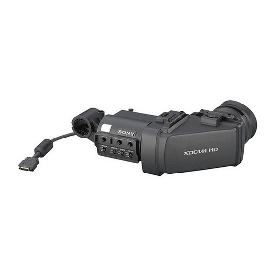
    Überblick Hinweise zur Bedienung Der CBK-VF01 HD Electronic Viewfinder ist ein Einsatzort 3,5-Zoll-Farbsucher mit LCD-Technologie. Wenn der Sucher in Umgebungen mit niedriger Der Sucher weist die folgenden Eigenschaften Temperatur verwendet wird, stehen unter auf: Umständen in der ersten Zeit nach dem Hohe Auflösung und breiter Blickwinkel...
  • Seite 37: Namen Und Funktionen Der Teile

    Sucherobjektiv Namen und Funktionen Lassen Sie das Sucherobjektiv nicht längere Zeit der Teile in Richtung einer starken Lichtquelle zeigen, z. B. in die Sonne. Wenn das Sonnenlicht oder Licht von einer anderen starken Lichtquelle von der Linse gebündelt wird, kann dies zu Beschädigungen der LCD-Anzeige oder Bränden führen.
  • Seite 38 g Kontrolleuchte o Sucherkabel Leuchtet, wenn die Aufzeichnung durch Drücken p Mikrofonhalter der Taste REC START an der Kamera, der Taste VTR am Objektiv oder der Taste VTR auf der Fernbedienung gestartet wurde. Blinkt zur Warnung bei Unregelmäßigkeiten. h Regler PEAKING Drehen Sie diesen Regelung im Uhrzeigersinn, um die Bildschärfe einzustellen und die Fokussierung zu erleichtern.
  • Seite 39: Anbringen Des Suchers An Der Kamera

    Verbinden Sie den Sucheranschluss mit Anbringen des Suchers dem Anschluss VF (rechteckig) der Kamera. an der Kamera Anschluss VF (rechteckig) VORSICHT Bei angebrachtem Sucher darf das Sucherobjektiv nicht in Richtung der Sonne zeigen. Andernfalls könnte durch das Objektiv eintretendes Sonnenlicht m Sucher gebündelt werden und einen Brand verursachen.
  • Seite 40: Einstellen Der Neigung

    Einstellen der Neigung Einstellen des Fokus und der Bildanzeige Sie können die Neigung des Suchers einstellen. Einstellen des Fokus Stellen Sie durch Drehen des Diopter- Einstellrings die optimale Bildschärfe ein. Vertikales Spiegeln der Anzeige (Text- Bild-Richtung) Der Sucher kann um bis zu 180 Grad in Richtung Motiv gedreht werden.
  • Seite 41: Anheben Des Suchertubus Und Des Suchereinblicks

    Anheben des Suchertubus Anheben des Drücken Sie auf den Clip an der Unterseite des Suchertubus und des Gerätes, um den Suchertubus zu lösen und hochzuklappen. Suchereinblicks Er wird in einer 120-Grad-Position arretiert. Sie können den LCD-Bildschirm im Sucher oder dessen Spiegelbild betrachten, indem Sie den Suchertubus oder den Suchereinblick anheben.
  • Seite 42: Horizontales Spiegeln Der Anzeige (Text-Bild-Richtung)

    Abnehmen des Suchertubus Horizontales Spiegeln der Anzeige (Text- Bild-Richtung) Indem Sie den Schalter MIRROR auf L/R stellen, können Sie das Bild und weitere auf dem Bildschirm angezeigte Informationen horizontal spiegeln. Drücken Sie zum Lösen des Suchertubus auf den Clip an der Unterseite des Gerätes.
  • Seite 43: Reinigen Des Lcd-Bildschirms Und Des Inneren Des Suchers

    Reinigen des LCD- Technische Daten Bildschirms und des Inneren des Suchers Allgemein Nehmen Sie zum Reinigen des LCD-Bildschirms oder des Inneren des Suchers den Sucher von der Stromversorgung Kamera ab und lösen Sie den Suchertubus vom 10,5 bis 17,0 V - (durch die Kamera) Sucher.
  • Seite 44 Version 1.10 erforderlich. Änderungen, die dem technischen Fortschritt dienen, bleiben vorbehalten. Hinweis Bestätigen Sie vor dem Gebrauch immer, dass das Gerät richtig arbeitet. SONY KANN KEINE HAFTUNG FÜR SCHÄDEN JEDER ART, EINSCHLIESSLICH ABER NICHT BEGRENZT AUF KOMPENSATION ODER ERSTATTUNG, AUFGRUND VON...
  • Seite 45 (residenziali), E2 (commerciali e industriali leggeri), E3 (esterni urbani) e E4 (ambienti EMC controllati, ad esempio studi televisivi). Per i clienti in Europa Il fabbricante di questo prodotto è la Sony Corporation, 1-7-1 Konan, Minato-ku, Tokyo, Giappone. La rappresentanza autorizzata per EMC e la sicurezza dei prodotti è...
  • Seite 46 Indice Descrizione generale .................. 47 Note per l’uso ..................... 47 Denominazione e funzioni dei componenti ..........48 Collegamento del mirino a una telecamera ..........50 Regolazione della posizione............50 Regolazione dell’angolo..............51 Regolazione della messa a fuoco e del display immagini......51 Sollevamento del cilindro del mirino e dell’oculare .......
  • Seite 47: Descrizione Generale

    Descrizione generale Note per l’uso Il mirino elettronico HD CBK-VF01 è un mirino Luogo d’impiego 3,5 pollici a colori LCD. Quando si utilizza il mirino in ambienti a bassa Questo mirino offre le seguenti caratteristiche: temperatura, i livelli di risoluzione dinamica...
  • Seite 48: Denominazione E Funzioni Dei Componenti

    Ottica del mirino Denominazione e Non lasciare l’ottica del mirino rivolta verso una funzioni dei componenti sorgente luminosa di elevata intensità, ad esempio la luce solare diretta. Se l’ottica mette a fuoco tale sorgente luminosa di elevata intensità, potrebbero verificarsi guasti e fenomeni di “burnout”...
  • Seite 49 g Indicatore TALLY L/R: Inverte l’immagine orizzontalmente. OFF: Non inverte l’immagine orizzontalmente. Si accende quando la registrazione viene avviata B/T: Inverte l’immagine verticalmente. premendo il tasto REC START sulla telecamera o il tasto VTR sull’obiettivo o il tasto VTR sul o Cavo del mirino telecomando.
  • Seite 50: Collegamento Del Mirino A Una Telecamera

    Accoppiare il connettore del mirino al Collegamento del mirino connettore VF (rettangolare) della telecamera. a una telecamera Connettore VF (rettangolare) ATTENZIONE Quando il mirino è collegato, non lasciare l’obiettivo del mirino rivolto verso il sole. La luce diretta del sole potrebbe entrare attraverso l’obiettivo, venire messa a fuoco nel mirino e provocare un incendio.
  • Seite 51: Regolazione Dell'angolo

    Regolazione dell’angolo Regolazione della messa a fuoco e del È possibile regolare l’angolo del mirino. display immagini Regolazione della messa a fuoco Ruotare il regolatore delle diottrie fino a quando l’immagine visualizzata non diventa nitida. Inversione dello schermo (visualizzazione immagini/testo) in senso verticale Il mirino può...
  • Seite 52: Sollevamento Del Cilindro Del Mirino E Dell'oculare

    Sollevamento del cilindro del mirino Sollevamento del Premere il clip sulla base per sganciare e ribaltare cilindro del mirino e il cilindro del mirino. Si blocca in posizione 120 gradi. dell’oculare È possibile guardare lo schermo LCD all’interno del mirino o la sua immagine rispecchiata, sollevando il cilindro del mirino o l’oculare.
  • Seite 53: Inversione Dello Schermo (Visualizzazione Immagini/Testo) In Senso Orizzontale

    Rimozione del cilindro del mirino Pulizia dello schermo LCD e della parte interna Quando si pulisce lo schermo LCD o l’interno del mirino, rimuovere il mirino dalla telecamera, staccare il cilindro del mirino dal corpo e fare attenzione a non danneggiare i componenti. Per maggiori dettagli sulla rimozione del cilindro del mirino, consultare “Collegamento del mirino a una telecamera”...
  • Seite 54: Caratteristiche Tecniche

    Nota Verificare sempre che l’apparecchio stia funzionando correttamente prima di usarlo. LA SONY NON SARÀ RESPONSABILE DI DANNI DI QUALSIASI TIPO, COMPRESI, MA SENZA LIMITAZIONE A, RISARCIMENTI O RIMBORSI A CAUSA DELLA PERDITA DI PROFITTI ATTUALI O...
  • Seite 55 (exteriores urbanos), y E4 (entorno con EMC controlada, p. ej., estudio de televisión). Para los clientes de Europa El fabricante de este producto es Sony Corporation, con dirección en 1-7-1 Konan, Minato-ku, Tokio, Japón. El Representante autorizado para EMC y...
  • Seite 56 Contenido Descripción general ................... 57 Notas de uso....................57 Nombres y funciones de los componentes..........58 Acople del visor a una cámara..............60 Ajuste de la posición ............... 60 Ajuste del ángulo................61 Ajuste del enfoque y la visualización de la imagen......... 61 Cómo se levantan el cilindro del visor y el ocular........
  • Seite 57: Descripción General

    Descripción general Notas de uso El Visor electrónico HD CBK-VF01 es un visor Lugar de utilización en color con pantalla LCD de 3,5 pulgadas. Cuando utilice el visor en entornos de baja Este visor incluye las siguientes funciones: temperatura, es posible que los niveles de Alta resolución y ángulo de visión panorámico...
  • Seite 58: Nombres Y Funciones De Los Componentes

    Objetivo del visor Nombres y funciones de No deje el objetivo del visor orientado hacia una los componentes fuente de luz intensa, como la luz solar. Si el objetivo enfocara la luz del sol o cualquier otra fuente de luz intensa, el panel LCD podría quemarse o podría originarse un incendio.
  • Seite 59 g Indicador de posición OFF: la imagen no se invierte. B/T: permite invertir la imagen verticalmente. Se ilumina cuando se inicia la grabación mediante la pulsación del botón REC START de la cámara, o Cable del visor el botón VTR del objetivo o el botón VTR de la unidad de control remoto.
  • Seite 60: Acople Del Visor A Una Cámara

    Acople el conector del visor al conector Acople del visor a una VF (rectangular) de la cámara. cámara Conector VF (rectangular) PRECAUCIÓN Cuando el visor esté acoplado, no deje el objetivo del visor orientado hacia el sol. La luz solar directa podría entrar a través del objetivo, quedar enfocada en el visor y provocar un incendio.
  • Seite 61: Ajuste Del Ángulo

    Ajuste del ángulo Ajuste del enfoque y la visualización de la Permite ajustar el ángulo del visor. imagen Ajuste del enfoque Gire el anillo de ajuste de dioptrías hasta que la imagen esté lo más definida posible. Inversión de la visualización (imagen/ indicación de texto) de manera vertical Es posible girar el visor como máximo 180 grados hacia la dirección que queda mirando al sujeto.
  • Seite 62: Cómo Se Levantan El Cilindro Del Visor Y El Ocular

    Cómo se levanta el cilindro del visor Cómo se levantan el Presione el clip de la parte inferior para liberarlo cilindro del visor y el y tire hacia arriba del cilindro del visor. Se bloquea en la posición de los 120 grados. ocular Es posible visualizar la pantalla LCD dentro del visor o su imagen invertida al levantar el cilindro...
  • Seite 63: Limpieza De La Pantalla Lcd Y Del Interior

    Desmontaje del cilindro del visor Limpieza de la pantalla LCD y del interior Cuando limpie la pantalla LCD o el interior del visor, extraiga el visor de la cámara, desmonte el cilindro del visor del cuerpo de la cámara y asegúrese de no dañar ninguno de los componentes.
  • Seite 64: Especificaciones

    El diseño y las especificaciones están sujetos a cambios sin previo aviso. Nota Verifique siempre que esta unidad funciona correctamente antes de utilizarlo. SONY NO SE HACE RESPONSIBLE POR DAÑOS DE NINGÚN TIPO, INCLUYENDO PERO NO LIMITADO A LA COMPENSACIÓN O PAGO POR LA PÉRDIDA DE GANANCIAS...
  • Seite 65 中文 机型名称:高清电子寻像器 使用产品前请仔细阅读本书,并请妥善 保管。 重要 设备铭牌位于底部。...
  • Seite 66 目录 概述....................67 使用注意事项 ................... 67 部件名称及功能................68 将取景器连接到摄像机上 ..............70 调整位置..................70 调整角度..................71 调整焦距和图像显示 ................ 71 抬起取景器镜头筒和接目镜.............. 72 清洁 LCD 屏幕及内部 ..............73 规格....................74 目录...
  • Seite 67: 使用注意事项

    概述 使用注意事项 CBK-VF01 HD 电子取景器是 3.5 英寸的 使用地点 LCD 彩色取景器。 在低温环境下使用取景器时,在开启电 此取景器有以下特点: 源后的片刻,动态分辨率水平可能会下 降。 高分辨率及宽可视角 取景器配有一块高分辨率的 LCD,水平 LCD 面板上的亮点或闪烁像素 分辨率达到 500 TV 线或更高。 此监视器所用 LCD 面板是采用高精密技 即使取下接目镜,也可通过取景器的大 术生产的,有效像素率达至少达到 LCD 屏幕轻松拍摄。 99.99%。因此有很少一部分像素可能会 稳定的图像 表现为 “亮点” ,或者始终是暗点 (黑 无论什么屏幕亮度, LCD 屏幕都能提供 色) 、变亮 (红色、绿色或蓝色)或者...
  • Seite 68: 部件名称及功能

    取景器镜头 部件名称及功能 请勿让取景器镜头直面强光源,例如日 光。 如果镜头将阳光或其他强光源光线聚 焦,可能会烧毁 LCD 面板或起火。 维护 • 使用吹灰器清除屏幕上的灰尘。 • 请勿使用稀释剂之类的溶剂清洁屏幕。 a 插头 连接至摄像机上的 VF 接口 (矩形) 。 b 制动器 左右滑动时,防止取景器从摄像机上掉 落。 c 取景接目罩 d 屈光度调节环 可实现最佳焦距调整。 e 接目镜 根据情况将接目镜抬起或拆下。 f 取景器镜头筒 根据情况将取景器镜头筒抬起或拆下。 部件名称及功能...
  • Seite 69 B/T:垂直翻转图像。 g 讯号指示灯 在按下摄像机上的 REC START 按钮、 o 取景器电缆 镜头上的 VTR 按钮或遥控器上的 VTR 按钮开始拍摄时亮起。 p 麦克风支架 如果发生异常,讯号指示灯会闪烁示 警。 h PEAKING 控制 顺时针转动此控件可调整图像锐度,使 调焦更轻松。它对摄像机的输出信号没 有影响。 i CONTRAST 控制 调整屏幕的对比度。它对摄像机的输出 信号没有影响。 j BRIGHT 控制 调整屏幕的亮度。它对摄像机的输出信 号没有影响。 k TALLY 开关 控制讯号指示灯。 HIGH:讯号指示灯亮度设置为高。 OFF:禁用讯号指示灯。 LOW:讯号指示灯亮度设置为低。...
  • Seite 70: 将取景器连接到摄像机上

    将取景器接口连接到摄像机的 VF 接 将取景器连接到摄像机 口 (矩形)上。 上 VF 接口 (矩形) 注意 连接取景器后,请勿让取景器镜头朝向 太阳。直射阳光会透过透镜而在取景器 上聚焦,从而导致起火。 注意 在连接取景器时,请注意以下几点。 • 在将取景器接口与摄像机的 VF 接口 (矩形)连接之前,务必先关闭摄像机 电源。如果在摄像机电源打开时进行 拆下取景器 连接,取景器可能无法正常工作。 您可以倒过来执行连接步骤来拆下取景 • 将取景器接口牢固地连接到摄像机的 器,但是还有一个额外操作:从定位靴 VF 接口 (矩形)上。如果连接得不牢 上拆下取景器时,先拉起制动器。 (请 固,视频上可能会出现干扰,或者讯 参见步骤 1 中的图。 ) 号指示灯可能无法正常工作。 调整位置 1 在摄像机上旋松取景器左右定位...
  • Seite 71: 调整角度

    调整角度 调整焦距和图像显示 可调整取景器的角度。 调整焦距 转动屈光度调节环,直到图像最清晰。 垂直翻转显示 (图像 / 文字显示) 可将取景器朝着拍摄对象的方向最多旋 转 180 度。 旋转后,屏幕中显示的图像及其他信息 会上下颠倒显示。要恢复正常显示,可 将 MIRROR 开关设置到 B/T 位置。 屈光度调节环 调整图像显示 通过如下控件调整显示亮度、对比度以 及峰值。 1 PEAKING 控制 2 CONTRAST 控制 3 BRIGHT 控制 调整焦距和图像显示...
  • Seite 72: 抬起取景器镜头筒和接目镜

    抬起取景器镜头筒 抬起取景器镜头筒和接 按下底部的卡扣松开取景器镜头筒,然 目镜 后将其向上掀起。 取景器镜头筒会在 120 度位置处锁定。 通过抬起取景器镜头筒或接目镜,可以 查看取景器内部的 LCD 屏幕或者其镜 像图像。 本节说明如何抬起及拆下取景器镜头 筒。也可以采用相同的方式抬起和拆下 接目镜。 通常在锁定位置进行使用。 LCD 屏幕 尽管可以在距锁定位置更远的距离打开 取景器镜头筒,但是一旦使其回到闭合 位置,便会再次在 120 度位置处锁定。 抬起取景器镜头筒和接目镜...
  • Seite 73: 清洁 Lcd 屏幕及内部

    拆下取景器镜头筒 清洁 LCD 屏幕及内部 如需清洁 LCD 屏幕及取景器内部,请 从摄像机上拆下取景器,然后拆下取景 器镜头筒,请小心不要损坏组件。 有关如何拆下取景器的详细信息,请参 阅 “将取景器连接到摄像机上” (第 页) 。 有关如何拆下取景器镜头筒的详细信 息,请参阅 “拆下取景器镜头筒” (第 页) 。 清除屏幕灰尘 使用吹灰器。 注意 请勿使用稀释剂等溶剂。 在恶劣的环境中使用取景器后 在恶劣的环境中 (例如沙滩、多尘区域 或温泉度假村)使用取景器后,请检查 以下各点。 • 使用气刷小心地去除取景器内部的所 有沙尘。 • 清洁接口的触点。 • 检查取景器是否正常工作。 按下底部的卡扣将取景器镜头筒松 开。 向上掀起取景器镜头筒。 滑动取景器镜头筒相对侧顶部的旋...
  • Seite 74 操作手册 (1) 20 ℃至+60 ℃ – 重量 选配附件 约680 g 取景器旋转组件 外部尺寸 BKW-401 单位:mm 相关附件 固态存储卡摄录一体机 PMW-500 1) 要将取景器连接至PMW-500,摄录 一体机上的固件版本必须为1.10或更 高。 设计与规格如有变更,恕不另行通知。 注意 在使用前请始终确认本机运行正常。 无论保修期内外或基于任何理由, SONY 对任何损坏概不负责。由于 本机故障造成的现有损失或预期利 3.5英寸彩色TFT透反式LCD 图像显示区尺寸 润损失,不作 (包括但不限于)退 76.8 × 43.2 mm (H/V, 16:9宽高比) 货或赔偿。 规格...
  • Seite 75 The material contained in this manual consists of information that is the property manutenzione dell’apparecchio ivi of Sony Corporation and is intended solely descritto, senza previo permesso scritto di Sony Corporation. for use by the purchasers of the equipment described in this manual.

Inhaltsverzeichnis