Herunterladen Inhalt Inhalt Diese Seite drucken
AERMEC FCLI 32 Installationshandbuch

AERMEC FCLI 32 Installationshandbuch

Kassetten-gebläsekonvektor mit inverter
Inhaltsverzeichnis

Werbung

Verfügbare Sprachen
  • DE

Verfügbare Sprachen

  • DEUTSCH, seite 42
VENTILCONVETTORE CASSETTE CON INVERTER
CASSETTE-TYPE FAN COIL WITH INVERTER
VENTILO-CONVECTEUR À CASSETTE AVEC INVERTER
KASSETTEN-GEBLÄSEKONVEKTOR MIT INVERTER
FAN COIL TIPO CASSETTE CON INVERTER
IT
GB
FCLI 32 (600x600)
FCLI 34 (600x600)
FCLI 42 (600x600)
FCLI 44 (600x600)
FCLI 62 (600x600)
FCLI 64 (600x600)
FR
DE
MANUALE INSTALLAZIONE
INSTALLATION MANUAL
MANUEL D'INSTALLATION
INSTALLATIONSHANDBUCH
MANUAL INSTALACIÓN
FCLI 82 (840x840)
FCLI 122 (840x840)
FCLI 124 (840x840)
ES
IFCLIIJ_1801_5190705_02

Werbung

Inhaltsverzeichnis
loading

Inhaltszusammenfassung für AERMEC FCLI 32

  • Seite 1 VENTILCONVETTORE CASSETTE CON INVERTER CASSETTE-TYPE FAN COIL WITH INVERTER VENTILO-CONVECTEUR À CASSETTE AVEC INVERTER KASSETTEN-GEBLÄSEKONVEKTOR MIT INVERTER FAN COIL TIPO CASSETTE CON INVERTER FCLI 32 (600x600) FCLI 82 (840x840) FCLI 34 (600x600) FCLI 122 (840x840) FCLI 42 (600x600) FCLI 124 (840x840)
  • Seite 2 10 years for any future reference. AERMEC S.p.A. declines all responsibility for any damage whatsoe- All the information in this manual must be carefully read and ver caused by improper use of the machine, and a partial or super- understood.
  • Seite 3 INDICE DICHIARAZIONE DI CONFORMITÀ DECLARATION OF CONFORMITY DÉCLARATION DE CONFORMITÉ KONFORMITÄTSERKLÄRUNG DECLARACIÓN DE CONFORMIDAD Trasporto • Simboli di sicurezza Transport • Safety symbols Transport • Symboles de sécurité Transport • Sicherheitssymbole Transporte • Símbolos de seguridad Italiano English Français Deutsche Español...
  • Seite 5 TRASPORTO • TRANSPORT • TRANSPORT • TRANSPORT • TRANSPORTE NICHT nass machen. NON bagnare. Tenere KEEP DRY. Keep out of NE PAS mouiller. Tenir à NO mojar. Conservar Vor Regen geschützt al riparo dalla pioggia. the rain. l’abri de la pluie. protegido de la lluvia.
  • Seite 6 INDICE Informazioni importanti • Manutenzione • Imballo Funzionamento • Uso Descrizione • Versioni • Limiti di funzionamento Componenti principali • Descrizione dei componenti Informazioni per l'installazione Installazione dell'unità Installazione e sostituzione del filtro Collegamenti idraulici Collegamenti scarico condensa Collegamento aspirazione aria esterna Collegamento per mandata aria in un locale attiguo Collegamenti elettrici Dimensioni...
  • Seite 7: Non Usare Il Ventilconvettore In Modo Improprio

    INFORMAZIONI IMPORTANTI E MANUTENZIONE di età non inferiore a 8 anni e da persone con estate. ridotte capacità fisiche, sensoriali o mentali, In estate una temperatura troppo bassa com- ATTENZIONE: il ventilconvettore è o prive di esperienza o della necessaria porta maggiori consumi elettrici.
  • Seite 8 FUNZIONAMENTO Le istruzioni per il funzionamento sono contenute nel manuale fornito con il pannello comandi Posizione alette (GLLI10) (GLLI10N) (GLLI100) (GLLI100N) (GLLI100EH) (GLFLI10) (GLFI10N) (GLFI10M) (GLFI10EH) Nel funzionamento in riscaldamento si consiglia una apertura delle Per una migliore resa termica dell'accessorio griglia sia in riscalda- alette di 20°, indicata con una linea in rilievo sulle alette (vedi figure).
  • Seite 9: Descrizione Dell'unità

    Ventilconvettore Tipo Cassette con Inverter per installazione in contro soffitto, integrabile nelle pannellature standard 600x600 e 840x840 GRANDEZZE DISPONIBILI I ventilconvettori cassette della serie FCLI sono disponibili in: Per impianti a 2 tubi Per impianti a 4 tubi FCLI 32 (600x600) FCLI 34 (600x600) FCLI 42 (600x600) FCLI 44 (600x600) FCLI 62 (600x600)
  • Seite 10: Componenti Principali

    COMPONENTI PRINCIPALI 1 Griglia con filtro aria (GLLI-GLFI) 6 Basamento 11 Valvola di sfiato aria 2 Deflettore mandata aria (GLLI-GLFI) 7 Staffe di fissaggio 12 Semitranciato, raccordo per mandata aria 3 Cornice griglia (GLLI-GLFI) 8 Scatola elettrica in un locale attiguo 4 Bacinella 9 Attacchi idraulici (solo per 4 tubi) 13 Scarico condensa...
  • Seite 11 trifugo di nuova concezione studiato per plastica Øest. 16mm. L’aspirazione avviene attraverso griglia centra- ottenere una bassa emissione sonora, bilan- le, la mandata attraverso le fessure perime- ALLARME: quando il livello della condensa nella ciato dinamicamente e staticamente. trali orientabili manualmente. In materiale bacinella raggiunge il limite prefissato, l'al- Il motore elettrico brushless trifase è...
  • Seite 12 - La cornice della griglia deve essere posizionata posizione orizzontale. in modo che il vetrino con il logo AERMEC sia - Portare le linee idrauliche attraverso il corrispondente all'angolo della scatola elettrica. controsoffitto in corrispondenza della piastra...
  • Seite 13 INSTALLATION "MODULE 600" GLLI10 GLFI10...
  • Seite 14 - C a p o v o l g e r e s c a t o l a d e l il logo AERMEC sia corrispondente ventilconvettore cassette FCLI. - Rimuovere la scatola. all'angolo della elettrica.
  • Seite 15 - Togliere la vite di bloccaggio dello spor- - Eseguire le manutenzioni necessarie. In caso si rendesse necessario accedere tello d'angolo con il logo Aermec. - Rimontare il tutto seguendo la procedu- alla scatola elettrica per manutenzioni, - Togliere le 2 viti di bloccaggio della sca- ra inversa allo smontaggio.
  • Seite 16: Collegamenti Idraulici

    COLLEGAMENTI E’ necessario che le condutture dell’acqua, dello scarico condensa e il circuito elettrico siano già stati previsti. COLLEGAMENTI IDRAULICI Gli attacchi idraulici sono con raccordi a battuta in questo caso utilizzare le guarnizioni Le tubazioni di andata e ritorno devono essere piana completi di guarnizionii di tenuta a corredo, l’accessorio è...
  • Seite 17: Collegamenti Elettrici

    COLLEGAMENTI DI SCARICO CONDENSA Nel funzionamento in raffreddamento l’unità interna Il dispositivo di sollevamento in caso di allarme, sottrae umidità all’aria. L’acqua di condensa interrompe il flusso dell’acqua nella batteria. 1/50 ~ 1/100 dev'essere eliminata raccordando l’apposito La bacinella è dotata di un foro di troppo pieno per attacco di scarico con la tubazione dell’impianto di assicurare la fuoriuscita dell’acqua di condensa scarico condensa.
  • Seite 18 INDEX Important information • Maintenance • Packaging Operation • Use Description • Versions • Operating limits Main components • Description of components Installation information Unit installation Installing and replacing the filter Plumbing connections Condensate discharge connections External air suction connection Connection for air delivery in an adjacent room Electrical connections Dimensions...
  • Seite 19: Packaging

    IMPORTANT INFORMATION AND MAINTENANCE If the supply cord is damaged, it must be avoid differences over 7°C between the replaced by the manufacturer, its service outdoor temperature and the tempera- WARNING: the fan coil is con- agent or similarly qualified persons in ture inside the room in summer.
  • Seite 20 OPERATION The operating instructions can be found in the manual supplied with the control panel FIN POSITION (GLFLI10) (GLFI10N) (GLFI10M) (GLFI10EH) (GLLI100) (GLLI100N) (GLLI100) (GLLI100N) (GLLI100EH) For maximum efficiency of the grill accessory both in heating and In heating operation, a fin opening of 20° is recommended; this is indi- cooling it is necessary the maximum opening of the fins cated by a raised line on the fins themselves (see figures).
  • Seite 21: Description Of The Unit

    Cassette-type fan coil with Inverter for installation in suspended ceilings; can be integrated in standard 600x600 and 840x840 panelling. AVAILABLE SIZES The cassette-type fan coils of the FCLI range are available in: for 2-pipe systems For 4-pipe systems FCLI 32 (600x600) FCLI 34 (600x600) FCLI 42 (600x600) FCLI 44 (600x600) FCLI 62 (600x600) FCLI 64 (600x600)
  • Seite 22: Main Components

    MAIN COMPONENTS 1 Grille with air filter ( 6 Base unit 11 Air drain valve GLLI-GLFI 2 Air delivery deflector ( 7 Fastening brackets 12 Push-out, coupling for air delivery in an GLLI-GLFI 3 Grille frame ( 8 Electrical box adjacent room GLLI-GLFI 4 Tray...
  • Seite 23 drain valves, located respectively on the of the condensate that is produced by The form and opening of the intake slats highest and lowest point of the battery the unit and deposited in the polysty- were developed in order to have the circulation.
  • Seite 24 - The grille frame must be positioned so that the hold the frame. the relative chapter glass with the AERMEC logo is in line with the - Take the condensate discharge piping to the corner of the electric box. To install the FCLI unit, proceed as follows: relative fitting on the attachment plate - Fix the grille to the safety cable.
  • Seite 25 INSTALLAZIONE "MODULO 600" GLLI10 GLFI10...
  • Seite 26 - The grille frame must be positioned so - remove the box that the glass with the AERMEC logo is in - remove the packaging shells used to line with the corner of the electric box. protect the unit during transport - Fix the grille with the 4 screws.
  • Seite 27 - remove the screw that blocks the corner - carry out the maintenance work If you need to access the electric box for hatch (with the Aermec logo) - reassemble everything, following the maintenance purposes, observe the fol- - remove the 2 screws that block the elec-...
  • Seite 28: Water Connections

    WATER CONNECTIONS The water connections are made with the hot water coil; use the supplied gaskets. instruction booklet. flat fittings complete with seal gaskets The accessory comes complete with gaskets The delivery and return pips must be equal, (supplied). for connection to the system. suitably scaled and insulated to avoid In the 4-pipe version of the unit, it is Information for the correct installation of...
  • Seite 29: Condensate Discharge Connection

    CONDENSATE DISCHARGE CONNECTION During cooling operation the indoor device must never be interrupted. SC1 = Condensate discharge (male Ø 16mm) unit removes humidity from the air. The In the event of an alarm, the float device SC2 = Condensate discharge with siphon (male condensate water must be eliminated interrupts the flow of water in the coil.
  • Seite 30: Inhaltsverzeichnis

    TABLE DES MATIÈRES Informations importantes • Entretien • Emballage Fonctionnement • Utilisation Description • Versions • Limites de fonctionnement Composants principaux • Description des composants Informations pour l'installation Installation de l'unité Raccordements hydrauliques Raccords d'évacuation des condensats Raccord d'aspiration de l'air extérieur Raccord de refoulement de l'air dans une pièce voisine Raccordements électriques Installation et remplacement du filtre...
  • Seite 31: Informations Importantes • Entretien • Emballage

    INFORMATIONS IMPORTANTES ET ENTRETIEN cant, son agent de service ou une per- sonne qualifiée afin d'éviter tout danger ATTENTION : le ventilo-convec- teur est branché au réseau électrique et au circuit hydraulique: l’intervention de personnel sans la compétence tech- VENTILER LA PIÈCE nique spécifique peut entraîner des Il est conseillé...
  • Seite 32: Fonctionnement • Utilisation

    FONCTIONNEMENT Les instructions de fonctionnement sont contenues dans le manuel fourni avec le panneau de commande. Position ailettes (GLLI10) (GLLI10N) (GLLI100) (GLLI100N) (GLLI100EH) (GLFLI10) (GLFI10N) (GLFI10M) (GLFI10EH) Pour le fonctionnement en chauffage, nous conseillons une Pour une efficacité thermique maximale de l'accessoire de gril à la ouverture des ailettes de 20º, indiquée par une ligne en fois dans le chauffage et le refroidissement, il est nécessaire l'ouver- ture maximale des ailettes...
  • Seite 33: Description De L'unité

    600x600 et 840x840 TAILLES DISPONIBLES Les ventilo-convecteurs à cassette de la série FCLI sont disponibles en : Pour installations à 2 tuyaux Pour installations à 4 tuyaux FCLI 32 (600x600) FCLI 34 (600x600) FCLI 42 (600x600) FCLI 44 (600x600) FCLI 62 (600x600)
  • Seite 34: Composants Principaux • Description Des Composants

    COMPOSANTS PRINCIPAUX 1 Grille avec filtre air ( 6 Socle 10 Raccords hydrauliques (2 tuyaux) GLLI-GLFI 2 Déflecteur refoulement air ( 7 Etriers de montage 11 Vanne de purge d'air GLLI-GLFI 3 Cadre grille ( 8 Armoire électrique 12 Partie prédécoupée, raccord de GLLI-GLFI 4 Bac 9 Raccords hydrauliques (seulement pour...
  • Seite 35: Informations Pour L'installation

    et des ailettes en aluminium ondulé ou à Le dispositif d'évacuation des condensats est la meilleure distribution possible de l'air, turbulence. Elles sont conçues pour avoir indispensable pour évacuer les condensats aussi bien pour le fonctionnement en été une surface optimale d'échange thermique. produits par l'unité...
  • Seite 36 à ce que le verre avec le logo pour soutenir le châssis. - Effectuer les raccordements hydrauliques en AERMEC corresponde à l'angle du boîtier suivant les descriptions du chapitre sur ce sujet. électrique. Pour installer l’unité FCLI, effectuer les opérations - Amener les tubes d'évacuation des condensats...
  • Seite 37 INSTALLATION "MODULE 600" GLLI10 GLFI10...
  • Seite 38: Installation De L'unité

    - Appliquer les 4 brides d'installation de de manière à ce que le verre avec le logo l'unité. (voir figure) AERMEC corresponde à l'angle du boîtier électrique. - Si nécessaire, monter les éventuels acces- soires (résistances électriques, kit d'air neuf - Fixer la grille avec les 4 vis.
  • Seite 39 - Enlever la vis de blocage de la trappe angu- - Réaliser les entretiens nécessaires. Lorsqu'il est nécessaire d'accéder au boîtier laire qui présente le logo d'Aermec. - Remonter l'ensemble en suivant la pro- électrique pour un entretien, respecter - Enlever les 2 vis de blocage du boîtier cédure inverse de celle respectée pour le...
  • Seite 40: Raccords Hydrauliques

    RACCORDEMENTS Il est nécessaire que les conduites d'eau, d'évacuation des condensats ainsi que du circuit électrique aient déjà été prévues. RACCORDS HYDRAULIQUES Les raccords hydrauliques sont des raccords L'accessoire est équipé de joints pour le doivent être égales, de dimensions à...
  • Seite 41: Raccords D'évacuation Des Condensats

    RACCORDS D'ÉVACUATION DES CONDENSATS Lors du fonctionnement en mode refroidisse- Il ne faut jamais couper l’alimentation élec- (mâle Ø 16 mm) Assurer une coupe verticale ment, l'unité intérieure élimine l'humidité de trique du dispositif de pompe flottante. d'au moins 5 cm (à partir de la sortie de la l'air.
  • Seite 42 INHALT Wichtige Informationen • Wartung • Verpackung Betrieb • Verwendung Beschreibung • Ausführungen • Betriebsgrenzen Hauptkomponenten • Beschreibung der Komponenten Hinweise zur Installation Installation der Einheit Wasseranschlüsse Anschlüsse des Kondensatablaufs Anschluss der Außenluftansaugung Anschluss für Luftvorlauf in einem angrenzenden Raum Elektrische Anschlüsse Installation und Austausch des Filters Abmessungen...
  • Seite 43: Den Gebläsekonvektor Nicht Unsachgemäss Benutzen

    WICHTIGE INFORMATIONEN UND WARTUNG qualifizierte Person, um eine Gefahr zu erfolgt, muss der Filter häufiger gereinigt vermeiden,. werden). ACHTUNG: Der Gebläsekonvektor ist mit dem Stromnetz und dem Wasserkreis verbunden. Somit kann ein Eingriff durch Personal, das nicht über spezielle tech- BELÜFTUNG DER UMGEBUNG nische Kenntnisse verfügt, Schäden Es wird empfohlen, die Umgebung, in...
  • Seite 44: Funktionsweise

    FUNKTIONSWEISE Die Hinweise zur Funktionsweise sind in dem mit dem Bedienfeld gelieferten Handbuch enthalten Stellung der Lamellen GLFI10 (GLLI100) (GLLI100N) (GLLI100) (GLLI100N) (GLLI100EH) Für maximale Wärmeeffizienz des Grillzubehörs sowohl Im Heizbetrieb wird ein Öffnungswinkel der Lamellen von 20° beim Heizen als auch Kühlen ist die maximale Öffnung der empfohlen.
  • Seite 45: Beschreibung Der Einheit

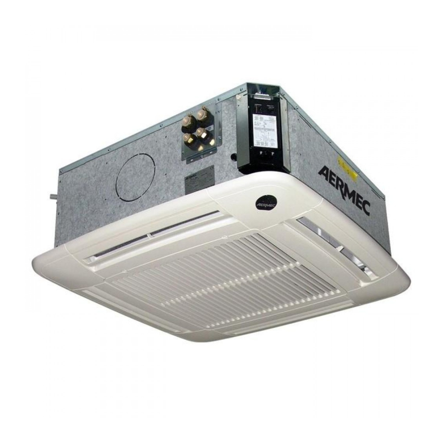
    Kassetten-Gebläsekonvektor mit Inverter zur Installation in der Zwischendecke, integrierbar in die Standardverkleidungen 600x600 und 840x840. ERHÄLTLICHE GRÖSSEN Die Kassetten-Gebläsekonvektoren der Serie FCLI sind erhältlich in: Für 2-Leiter-Systeme Für 4-Leiter-Systeme FCLI 32 (600x600) FCLI 34 (600x600) FCLI 42 (600x600) FCLI 44 (600x600) FCLI 62 (600x600) FCLI 64 (600x600)
  • Seite 46: Hauptkomponenten • Beschreibung Der Komponenten

    HAUPTKOMPONENTEN 1 Gitter mit Luftfilter ( 6 Untergestell 10 Wasseranschlüsse (2-Leiter-System) GLLI-GLFI 2 Ableiter Luftvorlauf ( 7 Befestigungsbügel 11 Entlüftungsventil GLLI-GLFI 3 Gitterrahmen ( 8 Schaltkasten 12 Halbstanzung, Anschluss für Luftauslass in GLLI-GLFI 4 Wanne 9 Wasseranschlüsse (nur für 4-Leiter- einen angrenzenden Raum 5 Inverter-Vorrichtung System)
  • Seite 47: Hinweise Zur Installation

    Die eingesetzten Austauscher sind mit Kupfer- und Reinigung mühelos zugängig. Das Gitter gehört zur Gittergruppen-Baureihe rohren und gefalzten Aluminiumlamellen GLLI100/GLLI10 GLLI100N/GLLI10N/ GLLI10M KONDENSATABLAUFEINRICHTUNG oder Turbolenz-Lamellen gefertigt. Sind (obligato- GLLI100EH/ GLFI10EH und GLLI20 Die Kondensatablaufeinrichtung ist für die für eine maximale Wärmetauschfläche risches Zubehör).
  • Seite 48: Empfohlene Installationsschablone

    - Der Rahmen des Gitters muss so positioniert werden, mens an der Zimmerdecke installieren. - Die Leitungen der Kondensatablauf-Einrichtung zum dass sich die Scheibe mit dem Logo AERMEC in der entsprechenden Anschluss an der Anschlussplatte Ecke des Schaltkastens befindet. Gehen Sie zur Installation der FCLI-Einheit wie folgt vor: führen.
  • Seite 49 INSTALLATION "MODUL 600" GLLI100 GLFI10...
  • Seite 50 - Der Rahmen des Gitters muss so positio- det wurden. niert werden, dass sich die Scheibe mit dem - Bringen Sie die 4 Installationsbügeln an der Logo AERMEC in der Ecke des Schaltkastens Einheit an. (siehe Abbildung) befindet. - Montieren Sie bei Bedarf das eventuelle - Befestigen Sie das Gitter mit den Zubehör (elektrische Widerstände, Bau-...
  • Seite 51 - Ziehen Sie den Schaltkasten nach unten heraus. - Entfernen Sie die Befestigungsschraube der - Führen Sie die erforderlichen Wartungsar- Sollte für Wartungszwecke ein Zugriff auf den Ecktür mit dem AERMEC Logo. beiten durch. Schaltkasten erforderlich sein, müssen die - Entfernen Sie die beiden Befestigungs-...
  • Seite 52: Wasseranschlüsse

    ANSCHLÜSSE Die Wasserleitungen, der Kondensatablauf und die elektrischen Leitungen müssen bereits vorbereitet sein. WASSERANSCHLÜSSE Die Wasseranschlüsse verfügen über den; das Zubehörteil ist mit den nötigen gleich, entsprechend dimensioniert und Anschlüsse mit flachem Anschlag, ein- Dichtungen für den Anlagenanschluss isoliert sein, um einen Wärmeverlust schließlich beiliegender Dichtungen.
  • Seite 53: Anschlüsse Zum Kondensatablauf

    ANSCHLÜSSE ZUM KONDENSATABLAUF Beim Kühlbetrieb entzieht die Inneneinheit der Luft heit darf nie unterbrochen werden. penausgang, oben) ihre Feuchtigkeit. Das Kondensat muss durch den Die Hubvorrichtung unterbricht bei einem Alarm Anschluss des entsprechenden Kondensatablaufs den Wasserfluss in den Wärmetauscher. an die Leitung der Kondensatablauf-Einrichtung Die Wanne ist mit einer Überlauföffnung ausge- beseitigt werden.
  • Seite 54 ÍNDICE Información importante • Mantenimiento • Embalaje Funcionamiento • Uso Descripción • Versiones • Límites de funcionamiento Componentes principales • Descripción de los componentes Informaciones para la instalación Instalación de la unidad Conexiones hidráulicas Conexiones descarga del agua de condensación Conexión aspiración de aire exterior Conexión para ventilación de aire en un local contiguo Conexiones eléctricas...
  • Seite 55 INFORMACIÓN IMPORTANTE Y MANTENIMIENTO VENTILAR EL AMBIENTE ATENCIÓN: El convector venti- Es aconsejable que ventile periódica- lador está conectado a la red eléctri- mente la habitación donde el fan coil ca y al circuito hidráulico: cualquier está instalado, especialmente si en dicho intervención por parte de personal no lugar se encuentran varias personas, o si cualificado puede producir daños al...
  • Seite 56 FUNCIONAMIENTO Las instrucciones para el funcionamiento están detalladas en el manual suministrado con el tablero de mandos Posición aletas GLFI10 (GLLI100) (GLLI100N) (GLLI100) (GLLI100N) (GLLI100EH) Para obtener la máxima eficiencia térmica del accesorio Para el funcionamiento en calefacción se aconseja una de la parrilla, tanto en la calefacción como en el enfria- apertura de las aletas de 20°, indicada con una raya en miento, es necesaria la apertura máxima de las aletas...
  • Seite 57: Descripción De La Unidad

    Fan coil Tipo Cassette con Inverter para instalación en falso techo, integrable a los paneles estándar 600x600 y 840x840 TAMAÑOS DISPONIBLES Los fan coils tipo cassette de la serie FCLI están disponibles en: Para instalaciones de 2 tubos Para instalaciones de 4 tubos FCLI 32 (600x600) FCLI 34 (600x600) FCLI 42 (600x600) FCLI 44 (600x600) FCLI 62 (600x600)
  • Seite 58: Componentes Principales

    COMPONENTES PRINCIPALES 1 Rejilla con filtro del aire (GLLI) 6 Zócalo 10 Conexiones hidráulicas (2 tubos) 2 Deflector ventilación aire (GLLI) 7 Abrazaderas de fijación 11 Válvula de ventilación de aire 3 Marco rejilla (GLLI) 8 Caja eléctrica 12 Semitroquelado, racor para ventilación 4 Bandeja 9 Conexiones hidráulicas de aire en un local contiguo...
  • Seite 59 Las baterías utilizadas tienen los tubos de limpieza. GLLI100/GLLI10 GLLI100N/GLLI10N/ GLLI10M cobre y las aletas de aluminio arrugadas o (accesorio GLLI100EH/ GLFI10EH y GLLI20 DISPOSITIVO DE DESCARGA DEL AGUA DE turbulenciadas. Están diseñadas para tener obligatorio). CONDENSACIÓN. la máxima superficie de intercambio térmi- El perfil y la abertura de las aletas de envío El dispositivo de descarga de condensación es co.
  • Seite 60 - El marco de la rejilla debe estar ubicado de realizar la instalación y el mantenimiento. - Efectuar las conexiones hidráulicas come se manera que el cristal con el logo AERMEC se - Instalar en el techo cuatro soportes con rosca indica en el capítulo correspondiente.
  • Seite 61 INSTALACIÓN "MÓDULO 600" GLLI100 GLFI10...
  • Seite 62 FCLI. - Retirar la caja. - El marco de la rejilla debe estar ubicado de manera que el cristal con el logo AERMEC - Retirar el embalaje utilizado para proteger la unidad durante el transporte. se corresponda con el ángulo de la caja - Colocar los 4 soportes de instalación en la...
  • Seite 63 - Quitar el tornillo de bloqueo de la tapa en - Ejecutar las tareas de mantenimiento nece- Si fuera necesario acceder a la caja eléctrica el vértice con el logo Aermec. sarias. para tareas de mantenimiento, atenerse a - Quitar los 2 tornillos de bloqueo de la caja...
  • Seite 64: Conexiones De Agua

    CONEXIONES Es necesario que las tuberías del agua, de la descarga del agua de condensación y el circuito eléctrico hayan sido previstas. CONEXIONES DE AGUA Las conexiones hidráulicas se realizan en dotación; el accesorio cuenta con juntas aisladas para evitar dispersiones térmicas mediante racores con tope plano y juntas para la conexión a la instalación.
  • Seite 65 CONEXIONES DE DESCARGA DEL AGUA DE CONDENSACIÓN Durante el funcionamiento en frío la unidad interna El dispositivo de transporte en caso de alarma, cal de al menos 5 cm (desde la salida quita humedad al aire. El agua de condensación interrumpe el flujo del agua en la batería.
  • Seite 66: Installation Et Remplacement Du Filtre

    INSTALLAZIONE E SOSTITUZIONE DEL FILTRO "Modulo 600"GLLI INSTALLATION AND REPLACEMENT OF THE "Module 600" FILTER GLLI INSTALLATION ET REMPLACEMENT DU FILTRE "Module 600" GLLI INSTALLATION UND AUSTAUSCH DES FILTERS "Modul 600" GLLI INSTALACIÓN Y SUSTITUCIÓN DEL FILTRO "Módul 600" GLLI INSTALLAZIONE E SOSTITUZIONE DEL FILTRO "Modulo 600"...
  • Seite 67: Dimensions

    DATI DIMENSIONALI • DIMENSIONS • DONNÉES DES LES DIMENSIONS • ABMESSUNGEN • DATOS DIMENSIONALES [mm] FCLI 32 FCLI 34 FCLI 36 FCLI 42 FCLI 44 FCLI 62 FCLI 64 KFLD FCLI FCLI 20,5 21,0 20,5 21,0 22,5...
  • Seite 68: Abmessungen

    DATI DIMENSIONALI • DIMENSIONS • DONNÉES DES LES DIMENSIONS • ABMESSUNGEN • DATOS DIMENSIONALES [mm] GLLI 10 GLLI 100 GLLI 100EH GLLI 100N GLFI 10 GLFI 10EH GLFI 10N GLFI 10M...
  • Seite 69: Probleme • Solution

    DATI DIMENSIONALI • DIMENSIONS • DONNÉES DES LES DIMENSIONS • ABMESSUNGEN • DATOS DIMENSIONALES [mm] FCLI 82 FCLI 122 FCLI 124 GLLI 20 GLL20 KFLD20 GLL20R KFLD20 KFL20 FCLI FCLI_ [kg]...
  • Seite 70: Problemi E Soluzioni

    PROBLEMI E SOLUZIONI PROBLEMA • PROBLEM PROBABILE CAUSA • PROBABLE CAUSE SOLUZIONE • REMEDY PROBLEME • PROBLEM CAUSE PROBABLE • MÖGLICHE URSACHE SOLUTION • ABHILFE PROBLEMA CAUSA PROBABLE SOLUCIÓN Scegliere la velocità corretta sul pannello comandi. Poca aria in uscita. Errata impostazione della velocità...
  • Seite 71 SCHEMI ELETTRICI • WIRING DIAGRAMS • SCHEMAS ELECTRIQUES • SCHALTPLÄNE • ESQUEMAS ELÉCTRICOS G l i s c h e m i e l ett r i c i s o n o s o g gett i a d u n co nt i n u o a g g i o r n a m e nto, è o b b l i gato r i o q u i n d i fa re r i fe r i m e nto a q u e l l i a b o rd o m a c c h i n a . A l l w i r i n g d i a g r a m s...
  • Seite 72 SCHEMI ELETTRICI • WIRING DIAGRAMS • SCHEMAS ELECTRIQUES • SCHALTPLÄNE • ESQUEMAS ELÉCTRICOS G l i s c h e m i e l ett r i c i s o n o s o g gett i a d u n co nt i n u o a g g i o r n a m e nto, è o b b l i gato r i o q u i n d i fa re r i fe r i m e nto a q u e l l i a b o rd o m a c c h i n a . A l l w i r i n g d i a g r a m s...
  • Seite 73 SCHEMI ELETTRICI • WIRING DIAGRAMS • SCHEMAS ELECTRIQUES • SCHALTPLÄNE • ESQUEMAS ELÉCTRICOS G l i s c h e m i e l ett r i c i s o n o s o g gett i a d u n co nt i n u o a g g i o r n a m e nto, è o b b l i gato r i o q u i n d i fa re r i fe r i m e nto a q u e l l i a b o rd o m a c c h i n a . A l l w i r i n g d i a g r a m s...
  • Seite 74 DATI IN ACCORDO CON IL REGOLAMENTO EU 2016/2281 • DATA IN ACCORDANCE WITH EU REGULATION 2016/2281 • DONNÉES SELON LA RÉGLE- MENTATION DE L’UE 2016/2281 • DATEN GEMÄSS EU 2016/2281-VERORDNUNG • DATOS SEGÚN LA REGULACIÓN DE LA UE 2016/2281 FCLI IMPIANTO A DUE TUBI - TWO-PIPE-SYSTEM - SYSTÈME À...
  • Seite 75: Auserbetriebsetzung Und Entsorgung Der Maschinenkomponenten

    MESSA FUORI SERVIZIO E SMALTIMENTO DEI COMPONENTI DELLA MACCHINA Quando dei componenti vengono rimossi per essere sostituiti o quando l’intera unità giunge al termine della sua vita ed è necessario rimuoverla dall’installa- zione, al fine di minimizzare l’impatto ambientale, rispettare le seguenti prescrizioni per lo smaltimento: •...
  • Seite 76 AERMEC S.p.A. si riserva la facoltà di apportare in qualsiasi momento tutte le modifiche ritenute necessarie per il miglioramento del prodotto. Les données mentionnées dans ce manuel ne constituent aucun engagement de notre part. Aermec S.p.A. se réserve le droit de modifier à tous moments les données considérées nécessaires à...

Inhaltsverzeichnis