Inhaltsverzeichnis
Werbung
Verfügbare Sprachen
Verfügbare Sprachen
Quicklinks
VENTILCONVETTORE
CON TERMOSTATO ELETTRONICO
FAN COIL
FOR UNIVERSAL INSTALLATION
WITH ELECTRONIC THERMOSTAT
VENTILO-CONVECTEUR
MUNI DE THERMOSTAT ÉLECTRONIQUE
GEBLÄSEKONVEKTOR
MIT ELEKTRONISCHEM THERMOSTAT
FAN COIL
PARA INSTALACIÓN UNIVERSAL
CON TERMOSTATO ELECTRÓNICO
Omnia UL N
Omnia UL 11 N
Omnia UL 16 N
Omnia UL 26 N
Omnia UL 36 N
Please fill out the requested information
Please fill out the requested information
M A N U A L E
D ' U S O
U S E
A N D
I N S T A L L A T I O N
MANUEL D'UTILISATION ET D'INSTALLATION
BEDIENUNGS- UND INSTALLATIONSANLEITUNG
MANUAL DE INSTRUCCIONES E INSTALACIÓN
PER INSTALLAZIONE UNIVERSALE
POUR INSTALLATION UNIVERSELLE
FÜR UNIVERSELLEN EINBAU
IULNLJ 1711 - 6976415_01
E
I N S T A L L A Z I O N E
M A N U A L
Werbung
Kapitel
Inhaltsverzeichnis
Fehlerbehebung

Verwandte Anleitungen für AERMEC Omnia UL N-Serie


Inhaltszusammenfassung für AERMEC Omnia UL N-Serie
- Seite 1 M A N U A L E D ’ U S O I N S T A L L A Z I O N E U S E A N D I N S T A L L A T I O N M A N U A L MANUEL D’UTILISATION ET D’INSTALLATION BEDIENUNGS- UND INSTALLATIONSANLEITUNG...
- Seite 2 Alle in diesem Handbuch enthaltenen Informationen auf- sich für die Garantiearbeiten als erforderlich erweisen sollten. merksam und vollständig lesen. Insbesondere auf die Die AERMEC S.p.A. übernimmt keine Haftung für Schäden aus Benutzungsanweisungen mit den Hinweisen "VORSICHT" oder dem unsachgemäßen Gebrauch des Gerätes und der teilweisen "ACHTUNG"...
- Seite 3 INDICE DICHIARAZIONE DI CONFORMITÀ DECLARATION OF CONFORMITY DÉCLARATION DE CONFORMITÉ KONFORMITÄTSERKLÄRUNG DECLARACIÓN DE CONFORMIDAD Trasporto • Simboli di sicurezza Transport • Safety symbols Transport • Symboles de sécurité Transport • Sicherheitssymbole Transporte • Símbolos de seguridad Italiano English Français Deutsche Español Dimensioni Dimensions...
- Seite 5 TRASPORTO • TRANSPORT • TRANSPORT • TRANSPORT • TRANSPORTE NICHT nass machen. NON bagnare. Tenere KEEP DRY. Keep out of NE PAS mouiller. Tenir NO mojar. Conservar Vor Regen geschützt al riparo dalla pioggia. the rain. à l’abri de la pluie. protegido de la lluvia.
-
Seite 6: Inhaltsverzeichnis
Desideriamo complimentarci con Voi per l'acquisto del ventilconvettore OMNIA UL_N Aermec. Realizzato con materiali di qualità superiore, nel rigoroso rispetto delle normative di sicurezza, "OMNIA UL_N" è di facile utilizzo e vi accompagnerà a lungo nell'uso. INDICE Informazioni importanti • Imballo Manutenzione •... -
Seite 7: Informazioni Importanti • Imballo
INFORMAZIONI IMPORTANTI ATTENZIONE: I ventilconvetto- elettrostatiche non può né raggiun- te il funzionamento, altrimenti la ri OMNIA sono concepiti per gere, né danneggiare le parti sen- polvere presente nell'aria andrà a funzionare in ambienti interni. sibili. sporcare le superfici della batteria. Se si effettuano misurazioni ATTENZIONE: il ventilconvetto- È... -
Seite 8: Manutenzione Ordinaria
Servizi trostaticamente, frequenza quin- te; consiste nella pulizia della Assistenza Aermec oppure da dicinale o settimanale in caso batteria, delle coclee smonta- soggetti in possesso dei requisiti di installazione in ambienti con... -
Seite 9: Funzioni Del Pannello Comandi
FUNZIONI DEL PANNELLO COMANDI La ventilazione è consentita solo con l’aletta aperta, è necessario aprirla manualmente. La chiusura dell’aletta provoca lo spegnimento della ventilazione. Pe r a c c e d e r e a l p a n n e l l o comandi sollevare lo sportello di protezione. -
Seite 10: Uso
Accensione - Per avviare il ventilconvettore ruotare la manopola e scegliere una velocità di ventilazione. - Per spegnere il ventilconvettore ruotare la manopola fino alla posizione Il ventilconvettore è spento. Nella condizione di spento il termostato continua a funzionare. Qualora la temperatura ambiente scenda sotto i 7°C e le condizioni di impianto lo consentano, il termostato attiverà... -
Seite 11: Visualizzazioni Per L'utente
VISUALIZZAZIONI LUMINOSE PER L’UTENTE (CONFIGURAZIONE STANDARD) Il LED D indica la richiesta di ventilazione: GIALLO - (Acceso) Le condizioni ambientali richiedono il funzionamento del ventilatore (quando il selettore di velocità è in posizione AUTO, V1, V2, V3). - (Spento) Le condizioni ambientali non richiedono il funzionamento del ventilconvettore oppure il selettore è... -
Seite 12: Funzionamento
FUNZIONAMENTO Il ventilconvettore OMNIA UL_N concen- coclee dei ventilatori ispezionabili (esegui- temperatura, la seconda per accendere/spe- tra elevate caratteristiche tecnologiche e bile solo da personale specializzato) con- gnere e impostare la velocità di ventilazione. funzionali che ne fanno il mezzo ideale di sentono di eseguire una pulizia accurata Le impostazioni fatte sul pannello comandi climatizzazione per ogni ambiente. -
Seite 13: Ambiente Di Funzionamento
tura ambiente, l’apertura della valvola è serie dev’essere sostituita con l’accessorio elettronica automaticamente è in grado sfasata rispetto alla ventilazione. sonda SW3N. di rilevare l’inconveniente e adottare un programma di emergenza, così da evitare • Sonda acqua • Contatto esterno disagi all’utente, avvisandolo nello stesso L’unità... -
Seite 14: Descrizione Dell'unità
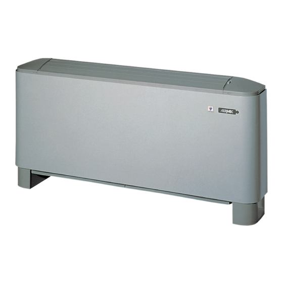
DESCRIZIONE DELL’UNITÀ SCOPO DELL'UNITÀ Il ventilconvettore è un terminale per il trattamento dell’aria di un ambiente sia nella stagione invernale sia in quella estiva. Versione Omnia UL_N Ventilconvettore con mobile per installazione universale, dotato di termostato elettronico multifunzione può essere installato- come unità... -
Seite 15: Fattori Correttivi Per Funzionamento Con Acqua Glicolata
FAT TO R I D I C O R R E Z I O N E N E L F U N Z I O NA M E N TO C O N AC QUA G L I C O L ATA Legenda: Perdite di carico Portata... -
Seite 16: Scarico Condensa
COMPONENTI PRINCIPALI 1 Pannello di comando (UL N) 7 Motore ventilatore 2 Scheda elettronica 8 Ventilatore 3 Mobile di copertura 9 Bacinella 4 Zoccoli (accessorio ZU) 10 Batteria di scambio termico 5 Struttura portante 11 Testata con alette orientabili 6 Filtro aria OMNIA UL_N DESCRIZIONE DEI COMPONENTI PAN NEL LO DI CO MANDI... -
Seite 17: Informazioni Per L'installazione
FILTRO ARIA PRECARICATO ELETTROSTATICAMENTE = Filtro serie UL Aermec = Filtro standard per ventilconvettori 0 , 7 2 , 0 0 , 3 0 , 5 1 , 0 Diametro particelle [µm] INSTALLAZIONE ATTENZIONE: I ventilconvetto- elettrici si richiedono le verifiche... -
Seite 18: Installazione Dell'unità • Rotazione Della Batteria
INSTALLAZIONE DELL’UNITÀ - Togliere il mantello svitando le viti. usare 4 tasselli ad espansione (non - Eseguire tutti i collegamenti. - Nella installazione a parete, si mantenga forniti), con caratteristiche adeguate al - Rimontare l’involucro. una distanza minima dal pavimento tipo di parete. -
Seite 19: Collegamenti Idraulici
COLLEGAMENTI E’ necessario che le condutture dell’acqua, dello scarico condensa e il circuito elettrico siano già stati previsti. COLLEGAMENTI IDRAULICI - Effettuare i collegamenti idraulici. La posizione e il diametro degli accessorio, per evitare gocciolamenti Per facilitare lo sfiato dell’aria dalla attacchi idraulici sono riportati nei d u r a n t e i l f u n z i o n a m e n t o i n batteria si consiglia di collegare il... -
Seite 20: Collegamenti Alla Scheda Elettronica • Impostazioni Di Rete
COLLEGAMENTI ALLA SCHEDA ELETTRONICA Legenda dei collegamenti: L - N = Alimentazione elettrica SP = Non presente MS = Microswitch 230 Vac - 50 Hz Connettore tipo edge SW = Sonda acqua Morsetti a vite Ingresso analogico Pannello Comandi - TTL = Seriale Sezione minima cavo = 0,5 mm Connettore tipo faston Locale TTL... -
Seite 21: Impostazioni Dip-Switch • Installazione E Sostituzione Del Filtro
1 2 3 4 5 6 7 8 1 2 3 4 5 6 7 8 INSTALLAZIONE DEL FILTRO DELL’ARIA PRECARICATO ELETTROSTATICAMENTE • • presso i centri assistenza Aermec). Installazione Caratteristiche - Rimuovere il telaio del filtro di Classe 2 (UL 900). - Seite 22 Congratulations on your purchase of the Aermec OMNIA UL_N fan coil. Made with materials of superior quality in strict compliance with safety regulations, "OMNIA UL_N" is easy to use and will have a long life. CONTENTS Important information • Package Maintenance •...
-
Seite 23: Important Information • Package
IMPORTANT INFORMATION you follow this rule, the energy (otherwise dust in the air could WARNING: OMNIA fan coils of the electrostatic charges can- soil the coil surface area). are designed for indoor use. not reach or damage the sensitive WHAT IS NORMAL parts. -
Seite 24: Routine Maintenance
Extraordinary maintenance can - cleaning the electrostatically pre- the fan fins, the basin and all only be performed by Aermec charged filter, every two weeks the parts in contact with the After-Sales Services or by people or weekly if the installation is in a treated air. -
Seite 25: Control Panel Functions
CONTROL PANEL FUNCTIONS Ventilation is only allowed with the fin open; it must be manually opened. The closure of the fin causes venti- lation to switch off. To access the control panel, lift the protection flap. Closing the master fan coil fin, the electronic thermostat card and the other fan coils in the network will carry on working. -
Seite 26: Use
Starting - To start up the fan coil, turn the knob and choose a ventilation speed. - To switch off the fan coil, turn the knob to the position. The fan coil is switched off. In the OFF condition, the thermostat carries on working. If the room temperature falls below 7°C, and the system conditions allow it, the thermostat will activate ventilation (anti-freeze function). -
Seite 27: Set Point - An Example Of A Setting
INDICATOR LIGHTS FOR THE USER (STANDARD CONFIGURATION) LED D indicates a ventilation request: YELLOW - (ON) The ambient conditions require the use of the fan (when the speed selector is on AUTO, V1, V2, V3) - (OFF) The ambient conditions do not require the use of the fan, or the selector is in the OFF (standby) position, or the fin is closed - (slow flashing) Operation mode managed by the centralised system. -
Seite 28: Operation
OPERATION The OMNIA UL_N fan coil concentrates ensure thorough cleaning of the unit (by be transmitted (without additional inter- hi-tech and highly functional features that specifically trained personnel), essential for faces) to a network with up to 5 fan coils, make it the ideal means of climate control installations in venues subject to crowding all equipped with their own electronic... - Seite 29 (changeover) is dependent on the tempera- circulation pump signal, etc. To obtain a better room temperature adjust- ture of the air in the room. In fan coil networks, only the external con- ment, the thermostat applies special Setting the dip-switch as a probe upstream of tact of the master fan coil is enabled.
-
Seite 30: Description Of The Unit
DESCRIPTION OF THE UNIT AIM OF THE UNIT The fan coil is a room air treatment terminal unit for both winter and summer operation. Omnia UL_N version A fan coil with cabinet, for universal installation and fitted with a multifunction electronic thermostat. It can be installed as an autonomous unit or within a network: it can, in fact, manage a network of a further 5 fan coils*. -
Seite 31: Correction Factors For Operation With Glycol Water
C O R R E C T I O N F A C T O R S W H E N O P E R A T I N G U S I N G G L Y C O L W A T E R Key: Pressure drops... -
Seite 32: Main Components • Description Of Components
MAIN COMPONENTS 1 Control panel (UL N) 7 Fan motor 2 Electronic card 8 Fan 3 Cabinet 9 Basin 4 Feet (accessory ZU) 10 Heat exchange coil 5 Load-bearing structure 11 Head with adjustable fins 6 Air filter OMNIA UL_N DESCRIPTION OF COMPONENTS CON TR OL PA NEL pipes. -
Seite 33: Installation Information
ELECTROSTATICALLY PRECHARGED AIR FILTER = Aermec UL range filter = Standard filter for fan coils 0 , 7 2 , 0 0 , 3 0 , 5 1 , 0 Particle diameter [µm] INSTALLATION insulation strength. with the treated air can be deposited... -
Seite 34: Installation Examples
UNIT INSTALLATION - Loosen the screws to remove the housing. supplied) with suitable characteristics - Make all the connections. - With wall-mounted units, keep a for the specific type of wall. - Reassemble the casing. minimum clearance of 80mm from - Apply any accessories. -
Seite 35: Water Connections
CONNECTIONS The water, condensate discharge and electrical circuit ducts must be provided for. WATER CONNECTIONS - Make the water connections. To help The position and diameter of the accessory), to prevent dripping during the bleeding of air from the coil, you water connections are shown in the the cooling function. -
Seite 36: Connections To The Electronic Card • Network Settings
CONNECTIONS TO THE ELECTRONIC CARD Connections key: L - N = Power supply SP = Not present MS = Microswitch 230V AC - 50Hz Edge-type connector SW = Water probe Screw clamps Analogue input Control panel - TTL = Local serial TTL Minimum cable section = 0.5mm Faston-type connector Removable-type connector... -
Seite 37: Dip-Switch Settings • Filter Installation And Replacement
1 2 3 4 5 6 7 8 1 2 3 4 5 6 7 8 INSTALLING THE ELECTROSTATICALLY PRECHARGED AIR FILTER • • (available as a spare part from Aermec Installation Characteristics After Sales centres). - Remove the suction filter frame from Class 2 (UL 900). - Seite 38 Veuillez accepter nos compliments les plus sincères pour avoir acheté le ventilo-convecteur OMNIA UL_N Aermec. Réalisé avec des matériaux de première qualité, dans le plus grand respect des normes de sécurité, "OMNIA UL_N" est facile à utiliser et destiné à durer longtemps.
-
Seite 39: Informations Importantes • Emballage
INFORMATIONS IMPORTANTES ATTENTION : Les ventilo-convec- détruire, les parties sensibles. car autrement la poussière qui se teurs OMNIA ont été conçus pour Si on effectue des mesures sur trouve dans l'air peut salir la surface fonctionner à l'intérieur. l'unité, il faut, avant de réaliser de la batterie. -
Seite 40: Entretien • Problèmes Et Solutions
être effectué que par les services après- trostatiquement, fréquence tous fait plus fréquemment ; Ces opé- vente Aermec ou bien par des per- les quinze jours ou une fois par rations comportent le nettoyage de sonnes possédant les conditions tech- semaine en cas d'installation dans la batterie, des vis sans fin démon-... -
Seite 41: Fonctions Du Panneau De Commande
FONCTIONS DU PANNEAU DE COMMANDE La ventilation n'est permise qu'avec l'ailette ouverte, il faut l'ouvrir manuellement. La fermeture de l'ailette provoque l'extinction de la ventilation. Pour accéder au panneau de com- mande, soulever la porte de protection. En fermant l'ailette du ventilo- convecteur maître, la carte du ther- mostat électronique et les autres ven- tilo-convecteurs du réseau continuent... -
Seite 42: Utilisation
UTILISATION Mise en marche - Pour démarrer le ventilo-convecteur, tourner la molette et choisir une vitesse de ventilation. - Pour éteindre le ventilo-convecteur, tourner la molette jusqu'à la position Le ventilo-convecteur est éteint. Même lorsque le ventilo-convecteur est éteint, le thermostat continue à fonctionner. Si la température ambiante descend au-dessous de 7 °C et les conditions de l'équipement le permettent, le thermostat activera la ventilation (Fonction Antigel). -
Seite 43: Affichages Pour L'utilisateur
AFFICHAGES LUMINEUX POUR L'UTILISATEUR (RÉGLAGE ORDINAIRE) La DEL D indique la demande de ventilation : JAUNE - (allumée) Les conditions environnementales exigent le fonctionnement du ventilateur (lorsque le sélecteur de vitesse est en position AUTO, V1, V2, V3). - (Éteint) Les conditions environnementales n'exigent pas le fonctionnement du ventilo-convecteur, ou le sélecteur est en position OFF (veille), ou bien l'ailette est fermée. -
Seite 44: Fonctionnement
FONCTIONNEMENT Le ventilo-convecteur OMNIA UL_N réunit des fin des ventilateurs susceptibles d'inspection et l'autre pour allumer/éteindre l'unité et pour caractéristiques technologiques et fonction- (opération qui ne peut être effectuée que par régler la vitesse de ventilation. nelles élevées qui en font le moyen de cli- du personnel spécialisé) permet d'effectuer un Les réglages réalisés sur le panneau de com- matisation idéal pour tous les types de pièce. - Seite 45 puissance frigorifique de l'unité et effectuer ment en amont de la vanne, la sonde d'eau tronique est automatiquement en mesure de un contrôle plus précis de la température de série doit être remplacée par l'accessoire relever l'inconvénient et d'adopter un pro- ambiante, l'ouverture de la vanne est décalée sonde SW3N.
-
Seite 46: Description De L'unité
DESCRIPTION DE L'UNITÉ OBJET DE L'UNITÉ Le ventilo-convecteur est un terminal pour le traitement de l’air d’un milieu, tant en hiver qu’en été. Version OMNIA UL_N Ventilo-convecteur avec carosserie pour installation universelle, doté de thermostat électronique multifonction, qui peut être installé comme unité... -
Seite 47: Facteurs De Correction Pour Le Fonctionnement Avec De L'eau Glycolée
FACTEURS DE CORRECTION DANS LE FONCTIONNEMENT AVEC EAU GLYCOLÉE Légende : Pertes de charge Débit Rendement EN MODE REFROIDISSEMENT EN MODE CHAUFFAGE EAU GLYCOLÉE À 10 % 17 °C 90 °C Température moyenne de l'eau glycolée Température moyenne de l'eau glycolée EAU GLYCOLÉE À... -
Seite 48: Composants Principaux • Description Des Composants
COMPOSANTS PRINCIPAUX 1 Panneau de commande (UL N) 7 Moteur du ventilateur 2 Carte électronique 8 Ventilateur 3 Carosserie de protection 9 Bac 4 Pieds (accessoire ZU) 10 Batterie d'échange thermique 5 Structure porteuse 11 Tête avec ailettes orientables 6 Filtre à air OMNIA UL_N DESCRIPTION DES COMPOSANTS PANNEAU DE COMMANDE... -
Seite 49: Exemples D'installation
FILTRE À AIR PRÉCHARGÉ ÉLECTROSTATIQUEMENT = Filtre de série UL Aermec = Filtre ordinaire pour ventilo-convecteurs 0 , 7 2 , 0 0 , 3 0 , 5 1 , 0 Diamètre des particules [µm] INSTALLATION ATTENTION : les ventilo-convec- sont requises pour les branchements les échangeurs de chaleur en cuivre-... -
Seite 50: Installation De L'unité • Rotation De La Batterie
INSTALLATION DE L'UNITÉ - Dévisser les vis de la couverture puis plat ; pour la fixation, employer 4 chevilles DES COMMUTATEURS DIP »). l'enlever. à expansion (non fournies), ayant des - Réaliser toutes les connexions. - En cas d'installation murale, il faut caractéristiques aptes au type de mur. -
Seite 51: Raccords Hydrauliques
RACCORDEMENTS Il est nécessaire que les conduites d'eau, d'évacuation des condensats ainsi que du circuit électrique aient déjà été prévues. RACCORDS HYDRAULIQUES - Effectuer les raccords hydrauliques. La position et le diamètre des raccords mentaire prévu à cet effet, disponible Pour faciliter la purge de l'air de la hydrauliques sont reportés dans les comme accessoire, pour éviter des... -
Seite 52: Branchements À La Carte Électronique • Réglages Du Réseau
BRANCHEMENTS À LA CARTE ÉLECTRONIQUE Légende des branchements : L - N = Alimentation électrique SP = absent MS = microrupteur 230 Vac ~ 50 Hz Connecteur encartable SW = sonde d'eau Bornes à vis Entrée analogique Panneau de commande - TTL = série local TTL Section minimale du câble = 0,5 mm Connecteur type Faston Connecteur démontable... -
Seite 53: Réglages Des Commutateurs Dip • Installation Et Remplacement Du Filtre
- Insérer le châssis du filtre d'aspiration de C'est la raison pour laquelle il est recom- l'unité. Résistance au feu mandé de le remplacer par un neuf tous les 2 ans (pièce de rechange disponible dans les centres d'assistance Aermec). IULNIJ 1711 - 4528500_01... - Seite 54 Wir möchten Sie zum Kauf des Gebläsekonvektors OMNIA UL_N von Aermec beglückwünschen. Aus Materialien von hoher Qualität und unter genauer Einhaltung der Sicherheitsbestimmungen hergestellt, lässt sich "OMNIA UL_N" einfach benutzen und wird Sie lange Zeit im Gebrauch begleiten. INHALTSVERZEICHNIS Wichtige Hinweise • Verpackung Wartung •...
-
Seite 55: Wichtige Hinweise • Verpackung
WICHTIGE HINWEISE Energie der elektrostatischen Entla- ACHTUNG: Die OMNIA Geblä- WÄHREND DES BETRIEBS dungen die empfindlichen Teile nicht sekonvektoren sind für den Lassen Sie während des Betriebs erreichen oder beschädigen. Betrieb in Innenräumen konzipiert. den Filter stets am Gebläsekonvektor Wenn Messungen am Gerät durch- montiert, anderenfalls verschmutzt geführt werden, müssen die elektro- ACHTUNG: Der Gebläsekonvek-... -
Seite 56: Wartung • Probleme Und Lösungen
Reinigung nur von einer Kundendienststelle wöchentlich bei Installation in sehr auch öfter vorgenommen werden; Aermec bzw. von qualifizierten staubigen Räumen); den angesam- sie besteht in der Reinigung des Technikern ausgeführt werden, die melten Staub mit einem Staubsauger Wärmetauschers, der abnehmbaren... -
Seite 57: Funktionen Der Bedientafel
FUNKTIONEN DER BEDIENTAFEL Die Lüftung ist nur bei offener Lamelle erlaubt, die manuell geöffnet werden muss. Schließt man die Lamelle, schaltet sich die Lüftung aus. Für den Zugriff auf die Bedientafel die Schutzklappe anheben. Schließt man die Lamelle des Master- Gebläsekonvektors bleiben die Platine des elektronischen Thermostats und die anderen in Netzschaltung verbun-... -
Seite 58: Gebrauch
GEBRAUCH Einschalten - Zum Anstarten des Gebläsekonvektors den Griff drehen und eine Gebläsedrehzahl auswählen. - Zum Ausschalten des Gebläsekonvektors den Griff bis in die Stellung drehen. Der Gebläsekonvektor ist ausgeschaltet. Im ausgeschalteten Zustand bleibt der Thermostat weiterhin in Betrieb. Sollte die Raumtemperatur unter 7°C absinken und der Zustand der Anlage es zulassen, aktiviert der Thermostat die Lüftung (Frostschutzfunktion). -
Seite 59: Leuchtanzeigen Für Den Benutzer (Standardkonfiguration)
LEUCHTANZEIGEN FÜR DEN BENUTZER (STANDARDKONFIGURATION) LED D zeigt die Lüftungsansteuerung an: GELB - (Eingeschaltet) Die Raumbedingungen erfordern den Gebläsebetrieb (bei Stellung des Drehzahlwahlschalters auf AUTO, V1, V2, V3). - (Ausgeschaltet) Die Raumbedingungen erfordern nicht den Betrieb des Gebläsekonvektors oder der Wahlschalter steht auf OFF (Stand-by) oder die Lamelle ist geschlossen - (Langsames Blinken) Betriebsart, die von der Zentralsteuerung gesteuert wird. -
Seite 60: Betriebsweise
BETRIEBSWEISE Der Gebläsekonvektor OMNIA UL_N ist ein Fremdkörper in den Raum gelangen können. Temperatur zu erhöhen oder abzusenken, den Konzentrat aus erstklassigen technologischen Durch die Möglichkeit, die Wanne und die anderen zum Ein- und Ausschalten und zur und funktionellen Eigenschaften, wodurch er Ventilatorschaufeln abzunehmen (nur durch Einstellung der Gebläsedrehzahl. -
Seite 61: Einsatzort
Ventil phasenverschoben im Vergleich zur An der Platine kann der Anschluss zu einem tronikkarte automatisch in der Lage die Lüftung. Außenkontakt hergestellt werden. Bei Störung zu erkennen und ein Notprogramm geschlossenem Außenkontakt konfiguriert zu starten, damit dem Benutzer keine Unan- •... -
Seite 62: Beschreibung Der Einheit
BESCHREIBUNG DER EINHEIT ZWECK DES GERÄTS Der Gebläsekonvektor ist eine Endeinheit für die Raumluftbehandlung sowohl für den Winter- als auch den Sommerbetrieb. Ausführung Omnia UL_N Gebläsekonvektor mit Verkleidung für universellen Einbau, ausgestattet mit elektronischem Multifunktions-Thermostat, instal- lierbar als eigenständiges Gerät oder in Netzschaltung mit bis zu 5 anderen Gebläsekonvektoren*. * Die in Netzschaltung verbundenen Gebläsekonvektoren müssen voreingestellte Modelle sein oder mit entsprechenden Zubehörteilen ausgestattet sein. -
Seite 63: Korrekturfaktoren Für Den Betrieb Mit Einer Wasser-Glykol-Mischung
K O R R E K T U R F A K T O R E N B E I M B E T R I E B M I T G L Y K O L W A S S E R Legende: Druckverluste Durchfluß... -
Seite 64: Kopfteil Mit Schwenkbaren Lamellen
HAUPTKOMPONENTEN 1 Bedientafel (UL N) 7 Motor des Ventilators 2 Platine 8 Ventilator 3 Verkleidung 9 Wanne 4 Sockel (Zubehörteil ZU) 10 Wärmetauscher für den thermischen Austausch 5 Trägerstruktur 11 Kopfteil mit schwenkbaren Lamellen 6 Luftfilter Omnia UL_N BESCHREIBUNG DER KOMPONENTEN BEDIENTAFEL mechanische Ausdehnung der Rohre darf nur von Personal mit spezifischen... -
Seite 65: Elektrostatisch Aufgeladener Luftfilter
ELEKTROSTATISCH AUFGELADENER LUFTFILTER = Filter der Serie UL Aermec = Standardfilter für Gebläsekonvektoren 0 , 7 2 , 0 0 , 3 0 , 5 1 , 0 Teilchendurchmesser [µm] INSTALLATION ACHTUNG: Die OMNIA Gebläse- - Messung des Isolationswiderstandes der Kunststoff unwiederbringlich beschädi-... -
Seite 66: Installation Der Einheit
INSTALLATION DER EINHEIT - Den Mantel durch Ausschrauben der rungsdübeln (nicht im Lieferumfang ten Gehäuse hantieren (siehe Kapitel Schrauben entfernen. enthalten) mit zur Wand passenden “EINSTELLUNGEN DIP-SCHALTER”). - Bei Wandinstallation ist eine Eigenschaften verwenden. - Alle Anschlüsse herstellen. Bodenhöhe von mindestens 80 mm - Die eventuellen Zubehörteile - Das Gehäuse wieder montieren. -
Seite 67: Wasseranschlüsse
ANSCHLÜSSE Die Wasserleitungen, der Kondensatablauf und die elektrischen Leitungen müssen bereits vorbereitet sein. WASSERANSCHLÜSSE - Nehmen Sie die Hydraulikanschlüsse Gerätebetrieb keineswegs. erhältliche zusätzliche Kondensatwanne vor. Um das Entlüften des Austauschers Position und Querschnitte der zu installieren, um zu vermeiden, dass zu vereinfachen, ist die Wasserablauf- Anschlüsse finden Sie bei den Abmes- während des Kühlbetriebs Wasser runter... -
Seite 68: Anschlüsse An Die Elektronikkarte • Netzeinstellungen
ANSCHLÜSSE AN DIE ELEKTRONIKKARTE Legende der Anschlüsse: L - N = Stromversorgung SP = Nicht vorhanden MS = Mikroschalter 230 Vac - 50 Hz Edge-Verbinder SW = Wassertemperaturfühler Schraubklemmen Analoger Eingang Bedientafel - TTL = Seriell Lokal TTL Kleinster Kabelquerschnitt = 0,5 mm Faston-Stecker Ausziehbarer Stecker Größter Kabelquerschnitt = 2,0 mm... -
Seite 69: Einige Beispiele
Aus diesem Grund ist ein Austausch nach 2 - Den Filterrahmen wieder anbringen. Jahren empfehlenswert (der neue Filter ist - Den Saugfilterrahmen in das Gerät als Ersatzteil in den Kundendienststellen einsetzen. Feuerbeständigkeit der Fa. Aermec erhältlich). IULNIJ 1711 - 4528500_01... - Seite 70 Deseamos felicitarles por la compra del fan coil OMNIA UL_N Aermec. Realizado con materiales de calidad superior y mostrando un riguroso respeto a las normativas de seguridad, "OMNIA UL_N" se caracteriza por su fácil manejo y les acompañará durante mucho tiempo en su uso.
-
Seite 71: Informaciones Importantes • Embalaje
INFORMACIONES IMPORTANTES Si se realizan mediciones en la canal de envío del fan coil. ATENCIÓN: Los fan coils OMNIA unidad se deben, antes de rea- Durante el funcionamiento en calen- han sido diseñados para funcionar lizar las operaciones, descargar las tamiento puede sentirse un ligero en ambientes interiores. -
Seite 72: Mantenimiento • Problemas Y Soluciones
Servicios de electricidad estática: frecuencia de limpieza del aire, puede reali- Asistencia Aermec, o por alguien quincenal o semanal en caso de zarse con mayor frecuencia; con- que reúna los requisitos técnico- instalación en lugares con mucho... -
Seite 73: Funciones Del Tablero De Mandos
FUNCIONES DEL TABLERO DE MANDOS La ventilación es posible sólo con la aleta abierta, es necesario abrirla manualmente. El cierre de la aleta da lugar al apaga- do de la ventilación. Para acceder al tablero de mandos, levantar la tapa de protección. Si se cierra la aleta del fan coil mas- ter, la tarjeta del termostato electró- nico y los demás fan coils de la red... -
Seite 74: Uso
Encendido - Para encender el fan coil, gire el mando y seleccione una velocidad de ventilación. - Para apagar el fan coil, gire el mando hasta la posición El fan coil está apagado. En la condición de apagado, el termostato continúa funcionando. Cuando la temperatura ambiente descienda por debajo de los 7°C y las condiciones de la instalación lo permitan, el termostato activará... -
Seite 75: Visualizaciones Para El Usuario
INDICACIONES LUMINOSAS PARA EL USUARIO (CONFIGURACIÓN ESTÁNDAR) El LED D indica la solicitud de ventilación: AMARILLO - (Encendido) Las condiciones ambientales requieren el funcionamiento del ventilador (cuando el selector de velocidad está en posición AUTO, V1, V2, V3). - (Apagado) Las condiciones ambientales no requieren el funcionamiento del fan coil o el selector está... -
Seite 76: Funcionamiento
FUNCIONAMIENTO El fan coil OMNIA UL_N reúne elevadas ción realizada sólo por personal experto), rar la velocidad de ventilación. características tecnológicas y funcionales es posible limpiar profundamente también Las configuraciones que se realicen en el que lo convierten en el medio ideal para las partes internas, condición necesaria tablero de mandos se pueden transmitir climatizar cualquier ambiente. - Seite 77 realizar un control más preciso de la tem- sonda SW3N. En caso de averiarse una sonda, la tarjeta peratura ambiente, la apertura de la válvu- electrónica puede automáticamente medir • Contacto externo la está desfasada respecto a la ventilación. el inconveniente y adoptar un programa En la tarjeta se encuentra disponible la de emergencia, para evitar problemas al •...
-
Seite 78: Descripción De La Unidad
DESCRIPCIÓN DE LA UNIDAD OBJETIVO DE LA UNIDAD El fan coil es un terminal para el tratamiento del aire de un ambiente tanto en invierno como en verano. Versión Omnia UL_N Fan coil con mueble para la instalación universal, equipado con termostato electrónico multifunción, que puede instalarse como unidad autónoma o en red, de hecho puede controlar una red de 5 fan coils*. -
Seite 79: Factores De Corrección Para Funcionamiento Con Agua Glicolada
FACTORES DE CORRECCIÓN EN EL FUNCIONAMIENTO CON AGUA GLICOLADA Leyenda: Pérdidas de carga Caudal Potencia DE ENFRIAMIENTO DE CALENTAMIENTO AGUA GLICOLADA AL 10% 17 °C 90 °C Temperatura media del agua glicolada Temperatura media del agua glicolada AGUA GLICOLADA AL 20% 17 °C 90 °C Temperatura media del agua glicolada... -
Seite 80: Componentes Principales • Descripción De Los Componentes
COMPONENTES PRINCIPALES 1 Tablero de mando (UL N) 7 Motor ventilador 2 Tarjeta electrónica 8 Ventilador 3 Mueble de cobertura 9 Cubeta 4 Zócalos (accesorio ZU) 10 Batería de intercambio térmico 5 Estructura portante 11 Parte superior con aletas orientables 6 Filtro del aire OMNIA UL_N DESCRIPCIÓN DE LOS COMPONENTES... -
Seite 81: Ejemplos De Instalación
FILTRO DE AIRE PRECARGADO ELECTROSTÁTICAMENTE = Filtro serie UL Aermec = Filtro estándar para fan coils 0 , 7 2 , 0 0 , 3 0 , 5 1 , 0 Diámetro partículas [µm] INSTALACIÓN AT E N C I Ó N : L o s f a n c o i l s eléctricas, es necesario comprobar:... -
Seite 82: Rotación De La Batería
INSTALACIÓN DE LA UNIDAD - Quitar la cubierta desenroscando los completamente plana, para fijar los 4 “CONFIGURACIÓN DIP-SWITCH”). tornillos. tacos (no suministrados), adecuados - Realice todas las conexiones. - En la instalación en pared, disponer al tipo de pared. - Vuelva a montar la cubierta. una distancia mínima de 80 mm - Aplique los accesorios deseados. -
Seite 83: Conexiones Hidráulicas
CONEXIONES Es necesario que las tuberías del agua, de la descarga del agua de condensación y el circuito eléctrico hayan sido previstas. Conexiones hidráulicas - Realice las conexiones hidráulicas. normal de la unidad. de condensadas auxiliar (disponible Para facilitar la ventilación de la La posición y el diámetro de las como accesorio) para evitar el goteo batería, se aconseja conectar el tubo... -
Seite 84: Conexiones Con La Tarjeta Electrónica • Configuraciones De Red
CONEXIONES A LA TARJETA ELECTRÓNICA Leyenda de las conexiones: L - N = Alimentación eléctrica SP = No presente MS = Microswitch 230 Vac - 50 Hz Conector tipo edge SW = Sonda de agua Bornes de tornillo Entrada analógica Tablero de mandos - TTL = Serial Local TTL Sección mínima del cable = 0,5 mm Conector tipo faston... -
Seite 85: Configuraciones De Los Dip-Switch • Instalación Y Sustitución Del Filtro
INSTALACIÓN DEL FILTRO DE AIRE PRECARGADO ELECTROSTÁTICAMENTE • Instalación • Características (disponible como recambio en los centros de asistencia Aermec). - Retire el bastidor del filtro de Clase 2 (UL 900). aspiración de la unidad. De fácil extracción, se distribuye en •... -
Seite 86: Dimensioni
DIMENSIONI • DIMENSIONS • ABMESSUNGEN • DIMENSIONES [mm] 5 0 m 5 0 m UL 11N Larghezza • Width • Largeur • Breite • Longitud 1200 Altezza • Height • Hauteur • Höhe • Altura Profondità • Depth • Profondeur • Tiefe • Profundidad Altezza zoccoli •... - Seite 87 DIMENSIONI • DIMENSIONS • ABMESSUNGEN • DIMENSIONES [mm] 1 Testata con alette orientabili 2 Mobile di copertura 3 Struttura portante 4 Zoccolo UL 5 Spazio per i collegamenti 1 Head with adjustable fins 2 Cabinet 3 Load-bearing structure 4 Foot UL 5 Space for connections 1 Tête avec ailettes orientables 2 Carosserie de protection...
-
Seite 88: Schemi Elettrici
SCHEMI ELETTRICI • WIRING DIAGRAMS • SCHEMAS ELECTRIQUES • ELEKTRISCHE SCHALTPLÄNE • ESQUEMAS ELECTRICOS LEGENDA • KEY • LEGENDE • LEGENDE • LEYENDA = Interruttore generale • Master switch • Interrupteur général • Hauptschalter • Interruptor general = Morsettiera • Control board • Bornier • Klemmleiste • Caja de conexiones = Microinterruttore •... - Seite 89 SCHEMI ELETTRICI • WIRING DIAGRAMS • SCHEMAS ELECTRIQUES • ELEKTRISCHE SCHALTPLÄNE • ESQUEMAS ELECTRICOS LEGENDA • KEY • LEGENDE • LEGENDE • LEYENDA = Arancio = Orange = orange = Orange = Naranja = Bianco = White = blanc = Weiß = Blanco = Blu = Blue...
-
Seite 90: Servizio Assistenza Tecnica (Italia)
26022 Castelverde (CR) Tel. 0438 450269 - Fax 0438 450283 21020 Brebbia VA Tel. 0372 471637 - Fax 0372 471637 centrotecnico@ctmenegazzo.com EMILIA ROMAGNA Tel. 0332 971073 - Fax 0332982221 aerservice@aermec.it info@cielleclima.it TRIESTE - GORIZIA BOLOGNA MANTOVA LA CLIMATIZZAZIONE TRIESTE srl TORINO... - Seite 91 Tel. e Fax 0766 220650 Tel. 0372 471637 - Fax 0372 471637 Via M. Ricci, 16/A air.frigo@libero.it CATANZARO - CROTONE - COSENZA aerservice@aermec.it 60020 Palombina AN CAMPANIA A.E.C. IMPIANTI TECNOLOGICI SRL Tel. e Fax 071 889435 Via B. Miraglia, 60B/60C REGGIO EMILIA aersat2004@libero.it...
-
Seite 92: Auserbetriebsetzung Und Entsorgung Der Maschinenkomponenten
AERMEC S.p.A. si riserva la facoltà di apportare in qualsiasi momento tutte le modifiche ritenute necessarie per il miglioramento del prodotto. Les données mentionnées dans ce manuel ne constituent aucun engagement de notre part. Aermec S.p.A. se réserve le droit de modifier à tous moments les données considérées nécessaires à...