Werbung
Quicklinks
LINEPULS
Incremental magnetic encoders
SME12 • SME22 • SME52
Series
Complete documentation
available for download at www.lika.biz
Warning: encoders having order code ending with "/Sxxx" may have mechanical and electrical characteristics different from standard and be supplied with additional documentation for special connections (Technical Info).
Attenzione: gli encoder con codice di ordinazione finale "/Sxxx" possono avere caratteristiche meccaniche ed elettriche diverse dallo standard ed essere provvisti di documentazione aggiuntiva per cablaggi speciali (Technical info).
Achtung: Geräte, deren Bestellschlüssel mit der Kennung /Sxxx enden, können in ihren mech. und elektr. Eigenschaften vom Standard abweichen. Diese werden daher mit einer ergänzenden Dokumentation ausgeliefert (Technical info).
Atención: los encoders con código de pedido acabado en "/Sxxx" pueden tener características mecánicas y eléctricas diferentes a las básicas y documentación adicional relativa a conexiones especiales (Technical Info).
Attention: les codeurs avec code de commande terminant en "/Sxxx" peuvent avoir des caractéristiques mécaniques et électriques différentes du standard et documentation additionnelle pour les câblages spéciaux (Technical info).
EN
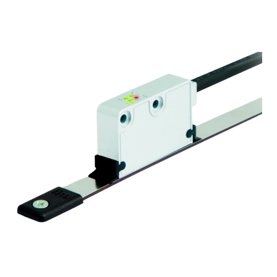
Mounting instructions
Make sure the mounting tolerances between the sensor and the
tape are always met. Avoid contact between the sensor and the
magnetic surface;
fix the sensor by means of two M3 15 mm min. long cylinder
head screws inserted in the provided holes; recommended
tightening torque: 1.1 Nm. Recommended minimum bend radius
of the cable: R 50 mm;
sensor can be mount in both directions. The arrow indicates the
positive counting direction (A leads B).
ES
Instrucciones de montaje
Asegurarse de que las tolerancias de montaje entre el sensor y la
banda magnética sean siempre respetadas. Evitar el contacto entre
el sensor y la superficie magnética;
fijar el sensor mediante los dos tornillos M3 de cabeza cilíndrica
(longitud min. 15 mm) insertados a través de los agujeros
previstos; par de apriete: 1,1 Nm. Radio de curvatura mínimo
recomendado del cable: R 50 mm;
es posible montar el sensor en las dos direcciones. La flecha indica
el sentido de conteo positivo (A precede B).
Pay attention to the mounting side!
Signals
M10 cable
0Vdc
Black
+Vdc
1
Red
A
Yellow
/A
Blue
B
Green
/B
Orange
0
2
White
2
/0
Grey
LS1
3
Brown
LS2
3
Violet
Shield
Shield
Installation has to be carried out with power supply disconnected.
L'installazione deve essere eseguita in assenza di tensione.
Der Anschluss darf nur bei ausgeschalteter Versorgungsspannung erfolgen.
La instalación sólo debe ser efectuada en ausencia total de tensión.
Le montage du dispositif doit être effectué en
IT
Verificare che le tolleranze di montaggio tra sensore e banda
magnetica siano sempre rispettate. Evitare il contatto tra sensore e
superficie magnetica;
fissare il sensore utilizzando due viti M3 a testa cilindrica di
lunghezza min. di 15 mm passanti nei due fori previsti; coppia di
serraggio raccomandata: 1,1 Nm. Raggio di curvatura minimo del
cavo raccomandato: R 50 mm;
è possibile montare il sensore nelle due direzioni. La freccia indica la
direzione di conteggio positivo (A precede B).
FR
S'assurer que les valeurs de tolérance de montage entre le capteur et
la bande magnétique soient toujours respectées. Éviter tous les
contacts entre le capteur et la surface magnétique;
fixer le capteur en utilisant deux vis type M3 à tête cylindrique
(longueur min. 15 mm) insérées dans les deux trous pourvus ;
couple de serrage recommandé : 1,1 Nm. Rayon de courbure
minimum recommandé du câble: R 50 mm;
on peut monter le capteur dans toutes les deux directions. La flèche
indique la direction de comptage positif (A devance B).
Sensor
Scale type
SME12
SME22
SME52
Electrical connections
Cavo M10
Kabel M10
Nero
Schwarz
Rosso
Rot
Giallo
Gelb
Blu
Blau
Verde
Grün
Arancione
Orange
Bianco
Weiß
Grigio
Grau
Marrone
Braun
Viola
Violett
Schermo
Schirm
absence totale de tension.
Istruzioni di montaggio
Instructions de montage
Gap sensor/MT magnetic scale (D)
w/o cover strip
w/ cover strip
MT10
0.1 – 0.5 mm
0.1 – 0.3 mm
MT20
0.1 – 1.0 mm
0.1 – 0.7 mm
MT50
0.1 – 2.0 mm
0.1 – 1.7 mm
Cable M10
Câble M10
Negro
Noir
Rojo
Rouge
Amarillo
Jaune
Azul
Bleu
Verde
Vert
Limit switch 1
Anaranjado
Orange
Blanco
Blanc
Limit switch 2
Gris
Gris
Marrón
Marron
Morado
Violet
Malla
Blindage
DE
Montagehinweise
Geber mit zwei M3 x 15 Schrauben befestigen und die
Montagerichtung zwischen Band und Geber beachten; angegebene
Montagetoleranzen einhalten; empfohlener Drehmoment max. 1,1
Nm; nur mit Magnetband MT10-20-50 einsetzen (s. MT10-20-50
Benutzeranleitung);
Mindestbiegeradius vom Kabel ist R ≥ 50 mm.;
der Sensor kann in beide Richtungen montiert werden. Positive
Zählrichtung, siehe Pfeil (B folgt A).
Gap LS1/2 Limit Switch
D1
D2
0.5 – 1.0 mm
7.5 mm
0.5 – 1.0 mm
7.5 mm
0.5 – 1.0 mm
7.5 mm
Diagnostic LEDs
E Error
Distance error: specified mounting tolerances are not met;
(blinking
frequency error: the sensor is travelling too fast.
red)
R Reference
LKM-1309 Reference detection and enabling. It is ON for the whole period
(lit green)
length.
Limit switch LS1: it lights up when the LS1 sensor detects the external
(lit green)
reference. The same as the low logic level (0Vdc) of LS1 signal.
Limit switch LS2: it lights up when the LS2 sensor detects the external
(lit green)
reference. The same as the low logic level (0Vdc) of LS2 signal.
See the order code. For example:
1
SMEx2-L-1-... +Vdc = +5Vdc ±5%
2
Reference signal R, see the order code
3
Limit switches LS1/2, see the "Electrical
safety" section on the back
Gap LKM-1309 Refer.
D1
D2
0.1 – 0.3 mm
7.3 mm
0.5 – 0.7 mm
7.5 mm
0.5 – 1.0 mm
7.5 mm
Werbung

Verwandte Anleitungen für Lika LINEPULS SME12 Serie


Inhaltszusammenfassung für Lika LINEPULS SME12 Serie
- Seite 1 Series Complete documentation available for download at www.lika.biz Warning: encoders having order code ending with "/Sxxx" may have mechanical and electrical characteristics different from standard and be supplied with additional documentation for special connections (Technical Info). Attenzione: gli encoder con codice di ordinazione finale “/Sxxx” possono avere caratteristiche meccaniche ed elettriche diverse dallo standard ed essere provvisti di documentazione aggiuntiva per cablaggi speciali (Technical info).
- Seite 2 Lika Electronic reserves the right to make changes in specifications without prior notice – Lika Electronic si riserva il diritto di apportare modifiche senza preavviso - Die Fa. Lika Electronic behält sich das Recht zu Änderungen ohne Vorankündigung...