Sentiotec WELLFUN LARGE Montageanleitung
Massivsauna
Vorschau ausblenden
Andere Handbücher für WELLFUN LARGE:
- Montageanleitung (21 Seiten) ,
- Montageanleitung (21 Seiten)

Verwandte Anleitungen für Sentiotec WELLFUN LARGE


Inhaltszusammenfassung für Sentiotec WELLFUN LARGE
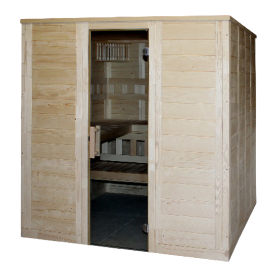
- Seite 1 Massivsauna WELLFUN LARGE 206 x 206 x 204 cm MONTAGEANLEITUNG Deutsch WELLFUN-L Version 11/19 Artikel-Nr. 1-030-302...
-
Seite 2: Montagevorbereitung
Lesen Sie diese Montageanleitung gut durch und bewahren Sie sie in der Nähe der Sauna auf. So können Sie jederzeit Produktinformationen nachlesen. Sie finden diese Montageanleitung auch im Downloadbereich unserer Webseite auf www.sentiotec.com/downloads. Wichtige Hinweise: ● Kontrollieren Sie, bevor Sie mit der Arbeit beginnen, anhand der Stückliste, ob alle Einzelteile auch tatsächlich mitgeliefert wurden. -
Seite 3: Benötigtes Werkzeug
Montageanleitung S. 3/22 Benötigtes Werkzeug ● Hammer und Beilageholz oder einen Gummihammer ● Akkuschrauber mit Bits für Kreuzschrauben und Torx ● Rollmaßband ● Bohrer mit Durchmesser 3 mm, 10 mm, 20 - 30 mm (für Stromkabel Saunaofen) ● Wasserwaage ● Innensechskant-Schlüssel 1,5 mm ●... -
Seite 4: Wartung Und Reinigung
Montageanleitung S. 4/22 Wartung und Reinigung ● Die Sauna sollte mit einem feuchten Tuch gereinigt werden. Verwenden Sie nur warmes Wasser - keine Reinigungsmittel. ● Wird die Sauna längere Zeit nicht benutzt, empfehlen wir, die Kabine einmal im Monat aufzuheizen. Harzgallen sind kein Reklamationsgrund. - Seite 5 Montageanleitung S. 5/22 Stückliste WELLFUN LARGE 2 Bodenrahmen Massivleisten 66 x 4 x 9 cm 3 Bodenrahmen Massivleisten 204 x 4 x 9 cm 4 Eckleisten 90° 193 x 6 x 6 cm 4 Seitenwände A/B 193 x 48 x 4 cm (1 Stk. mit Abluftausschnitt) 8 Seitenwände 193 x 48 x 4 cm...
- Seite 6 Montageanleitung S. 6/22 Abb 1.1 Schrauben 4 x 70 mm Abb 1.2...
- Seite 7 Montageanleitung S. 7/22 Schrauben 6 x 120 mm Abb 1.3 Abb 1.4 Abb 1.5...
- Seite 8 Montageanleitung S. 8/22 Abb 1.7 Abb 1.6 Elektroelement rechts - Abluft links hinten. Elektroelement links - Abluft rechts hinten Abb 1.8 Abb 1.9...
- Seite 9 Montageanleitung S. 9/22 Abb 1.10...
- Seite 10 Montageanleitung S. 10/22 Transportleiste vom Türstock entfernen Abb 1.12 Multiclip Abb 1.14 Abb 1.13...
- Seite 11 Montageanleitung S. 11/22 Schrauben 4 x 70 mm Abb 1.16 Abb 1.17 Abb.1.18...
-
Seite 12: Bankauflageleisten
Montageanleitung S. 12/22 Bankauflageleisten Schrauben 5 x 70 mm Abb.1.19 Abb.1.20 4 Stk. Schrauben 3 x 40 mm Abb 1.21... - Seite 13 Montageanleitung S. 13/22 Abb 1.22 Abb 1.23 Schrauben 4 x 60 mm Abb 1.24 Abb 1.25...
- Seite 14 Montageanleitung S. 14/22 Querbank von unten verschrauben - Schrauben 4 x 70 mm Abb 1.26 Abb 1.27 Schrauben 3 x 40 mm Abb 1.28 Abb 1.29...
- Seite 15 Montageanleitung S. 15/22 Abb 1.30 Abb 1.31 Schrauben 3 x 40 mm Abb 1.32...
- Seite 16 Montageanleitung S. 16/22 Silikonbeilage für Glastürbeschlä- ge auf beiden Seiten der Glastüre. Abb 1.33 Abb 1.34 Schrauben 4 x 30 mm Abb 1.35 Abb 1.36...
- Seite 17 Montageanleitung S. 17/22 Türdichtung von Glastüre. Abb 1.37 Abb 1.38 Abb 1.39 Überschubblech auf Glastüre aufstecken.. Abb 1.40...
- Seite 18 Montageanleitung S. 18/22 Silikoneinlage für Schraubenloch in Glastüre Abb 1.41 Innenseite Abb 1.42 Glastüre links oder rechts montierbar Abb 1.43...
- Seite 19 Montageanleitung S. 19/22 Schrauben 3 x 40 mm Abb 1.44 Abb 1.45...
- Seite 20 Montageanleitung S. 20/22 Beginnen Sie mit dem vorderen Dachkranz oberhalb der Türe Abb 1.46 Schrauben 3 x 40 mm Abb 1.47...
- Seite 21 Montageanleitung S. 21/22 Schraubloch-Abdeckungen Abb 1.48 Abb 1.49...
- Seite 22 Montageanleitung S. 22/22 GRUNDRISS WELLFUN LARGE 206 x 206 x 204 cm Kabine links oder rechts aufbaubar...
-
Seite 23: Instructions For Installation
Solid wood sauna WELLFUN LARGE 206 x 206 x 204 cm INSTRUCTIONS FOR INSTALLATION English WELLFUN-L Version 11/19 Artikel-Nr. 1-030-302... -
Seite 24: Preparing For Installation
These assembly instructions can also be found in the downloads section of our website: www.sentiotec.com/downloads. Important note: ● Before you begin work, check the parts list to ensure that all the individual parts have been delivered. -
Seite 25: Tools Required
Instructions for installation and use p. 3/22 Tools required ● Hammer with a wooden head or a mallet ● Cordless screwdriver with bits for cross-head screws and Torx ● Roller tape measure ● Drill bits with a diameter of 3 mm, 10 mm, 20 - 30 mm (for sauna heater power cable) ●... -
Seite 26: Maintenance And Cleaning
Instructions for installation and use p. 4/22 Maintenance and cleaning ● The sauna should be cleaned with a damp cloth. Only use warm water – no cleaning products. ● We recommend heating the cabin once a month if the sauna is not used for a long time. - Seite 27 Instructions for installation and use p. 5/22 Parts list WELLFUN LARGE 2 floor frame massive battens 66 x 4 x 9 cm 3 floor frames massive battens 204 x 4 x 9 cm 4 corner battens 90° 193 x 6 x 6 cm...
- Seite 28 Instructions for installation and use p. 6/22 fig. 1.1 screw 4 x 70 mm fig. 1.2...
- Seite 29 Instructions for installation and use p. 7/22 screw 6 x 120 mm fig. 1.3 fig. 1.4 fig. 1.5...
- Seite 30 Instructions for installation and use p. 8/22 fig. 1.7 fig. 1.6 Electrical element on the right side - Ventilation on the left back side Electrical element on the left side - Ventilation on the right back side fig. 1.8 fig. 1.9...
- Seite 31 Instructions for installation and use p. 9/22 Abb 1.10...
- Seite 32 Instructions for installation and use p. 10/22 Remove the transport batten from the door frame fig. 1.12 Multiclip Abb 1.14 Abb 1.13...
- Seite 33 Instructions for installation and use p. 11/22 screw 4 x 70 mm fig. 1.16 fig. 1.17 fig..1.18...
- Seite 34 Instructions for installation and use p. 12/22 Bench supporting battens screw 5 x 70 mm fig..1.19 fig..1.20 4 pcs. screws 3 x 40 mm fig. 1.21...
- Seite 35 Instructions for installation and use p. 13/22 fig. 1.22 fig. 1.23 screw 4 x 60 mm fig. 1.24 fig. 1.25...
- Seite 36 Instructions for installation and use p. 14/22 Screw the bench from the bottom- screw 4 x 70 mm fig. 1.26 fig. 1.29 fig. 1.27 screw 3 x 40 mm fig. 1.28 fig. 1.29...
- Seite 37 Instructions for installation and use p. 15/22 fig. 1.30 fig. 1.31 screw 3 x 40 mm fig. 1.32...
- Seite 38 Instructions for installation and use p. 16/22 Silicone ring for hinge plates on both sides of the glass door fig. 1.33 fig. 1.34 screw 4 x 30 mm fig. 1.35 fig. 1.36...
- Seite 39 Instructions for installation and use p. 17/22 Door seal from the glass door fig. 1.37 fig. 1.38 fig. 1.39 Put the sheet metal on the glass door fig. 1.40...
- Seite 40 Instructions for installation and use p. 18/22 Ring of silicone for screw hole in the glass door fig. 1.41 Inside fig. 1.42 Assembly of the glass door on the left or on the right side fig. 1.43...
- Seite 41 Instructions for installation and use p. 19/22 screw 3 x 40 mm fig. 1.44 fig. 1.45...
- Seite 42 Instructions for installation and use p. 20/22 Start with the frontal border edge above the door fig. 1.46 screw 3 x 40 mm fig. 1.47...
- Seite 43 Instructions for installation and use p. 21/22 Covering for the screw hole fig. 1.48 fig. 1.49...
- Seite 44 Instructions for installation and use p. 22/22 PLAN WELLFUN LARGE 206 x 206 x 204 cm Assembly of the cabin left or right...
- Seite 45 Sauna en bois massif WELLFUN LARGE 206 x 206 x 204 cm INSTRUCTIONS DE MONTAGE ET MODE D’EMPLOI Français WELLFUN-L Version 11/19 Référence 1-030-302...
-
Seite 46: Préparation Du Montage
Vous avez ainsi accès à tout moment aux informations sur le produit. Vous trouverez également ces instructions de montage dans la rubrique de téléchargement de notre site Internet www.sentiotec.com/downloads. Remarques importantes : ● Avant de commencer les travaux, vérifiez au moyen de la nomenclature si toutes les pièces ont bien été... -
Seite 47: Outils Requis
Instructions de montage et mode d’emploi S. 3/22 Outils requis ● Marteau et cales ou maillet en caoutchouc ● Visseuse électrique avec bits pour vis en croix et Torx ● Ruban de mesure ● Foret de 3 mm de diamètre, 10 mm, 20 - 30 mm (pour câble électrique poêle de sauna) ●... -
Seite 48: Entretien Et Nettoyage
Instructions de montage et mode d’emploi S. 4/22 Entretien et nettoyage ● Le sauna doit être nettoyé au moyen d’un chiffon humide. N’utilisez que de l’eau chaude, pas de détergent. ● Si le sauna n’est pas utilisé pendant une période prolongée, nous recom- mandons de chauffer la cabine une fois par mois. - Seite 49 Instructions de montage et mode d’emploi S. 5/22 Nomenclature WELLFUN LARGE 2 cadres de plancher, barres pleines 66 x 4 x 9 cm 3 cadres de plancher, barres pleines 204 x 4 x 9 cm 4 barres d’angle 90° 193 x 6 x 6 cm 4 parois latérales A/B 193 x 48 x 4 cm (1 pièce avec découpe d’aération)
- Seite 50 Instructions de montage et mode d’emploi S. 6/22 Fig 1.1 Vis 4 x 70 mm Fig 1.2...
- Seite 51 Instructions de montage et mode d’emploi S. 7/22 Vis 6 x 120 mm Fig 1.3 Fig 1.4 Fig 1.5...
- Seite 52 Instructions de montage et mode d’emploi S. 8/22 Fig 1.7 Fig 1.6 Élément électrique à droite - sortie d’air derrière à gauche Élément électrique à gauche - sortie d’air derrière à droite Fig 1.8 Fig 1.9...
- Seite 53 Instructions de montage et mode d’emploi S. 9/22 Fig 1.10...
- Seite 54 Instructions de montage et mode d’emploi S. 10/22 Retirer la barre de transport du cadre de porte Fig 1.12 Multiclip Fig 1.14 Fig 1.13...
- Seite 55 Instructions de montage et mode d’emploi S. 11/22 Vis 4 x 70 mm Fig 1.16 Fig 1.17 Fig 1.18...
- Seite 56 Instructions de montage et mode d’emploi S. 12/22 Baguettes d’appui de banc Vis 5 x 70 mm Fig 1.19 Fig 1.20 4 vis 3 x 40 mm Fig 1.21...
- Seite 57 Instructions de montage et mode d’emploi S. 13/22 Fig 1.22 Fig 1.23 Vis 4 x 60 mm Fig 1.24 Fig 1.25...
- Seite 58 Instructions de montage et mode d’emploi S. 14/22 Vissez le banc transversal par le dessous - vis 4 x 70 mm Fig 1.26 Fig 1.29 Fig 1.27 Vis 3 x 40 mm Fig 1.28 Fig 1.29...
- Seite 59 Instructions de montage et mode d’emploi S. 15/22 Fig 1.30 Fig 1.31 Vis 3 x 40 mm Fig 1.32...
- Seite 60 Instructions de montage et mode d’emploi S. 16/22 Insert en silicone pour ferrures de porte en verre des deux côtés de la porte en verre. Fig 1.33 Fig 1.34 Vis 4 x 30 mm Fig 1.35 Fig 1.36...
- Seite 61 Instructions de montage et mode d’emploi S. 17/22 Joint de la porte en verre. Fig 1.37 Fig 1.38 Fig 1.39 Fixez la tôle extérieure à la porte en verre. Fig 1.40...
- Seite 62 Instructions de montage et mode d’emploi S. 18/22 Insert en silicone pour le trou de vis dans la porte en verre Fig 1.41 Côté intérieur Fig 1.42 La porte en verre peut être montée à gauche ou à droite Fig 1.43...
- Seite 63 Instructions de montage et mode d’emploi S. 19/22 Vis 3 x 40 mm Fig 1.44 Fig 1.45...
- Seite 64 Instructions de montage et mode d’emploi S. 20/22 Commencez par la couronne de toit avant au-dessus de la porte Fig 1.46 Vis 3 x 40 mm Fig 1.47...
- Seite 65 Instructions de montage et mode d’emploi S. 21/22 Capuchons recouvrant les trous des vis Fig 1.48 Fig 1.49...
- Seite 66 Instructions de montage et mode d’emploi S. 22/22 COTES WELLFUN LARGE 206 x 206 x 204 cm Cabine à installer à gauche ou à droite...
- Seite 67 NOTIZEN / APPUNTI / NOTES / NOTE / NOTITIES ………………………………………………….....………………………………………………………………... ……………………………………………………………..……………………………………………………………... …………………………………………………………….....………………………………………………………... …………………………………………………….....………………………………………………………………... ……………………………………………………………..……………………………………………………………... ……………………………………………………………..……………………………………………………………... ……………………………………………………………..…………………………………………………………... …………………………………………………………….....………………………………………………………... …………………………………………………………….....………………………………………………………... …………………………………………………………….....………………………………………………………... …………………………………………………………….....………………………………………………………... …………………………………………………………….....………………………………………………………..…………………………………………………………….....………………………………………………………... …………………………………………………………….....………………………………………………………... …………………………………………………………….....………………………………………………………... …………………………………………………………….....………………………………………………………... …………………………………………………………….....………………………………………………………... …………………………………………………………….....………………………………………………………... …………………………………………………………….....………………………………………………………...
- Seite 68 GmbH | Division of Harvia Group | Oberregauer Straße 48, A-4844 Regau T +43 (0) 7672/22 900-50 | F -80 | info@sentiotec.com | www.sentiotec.com...