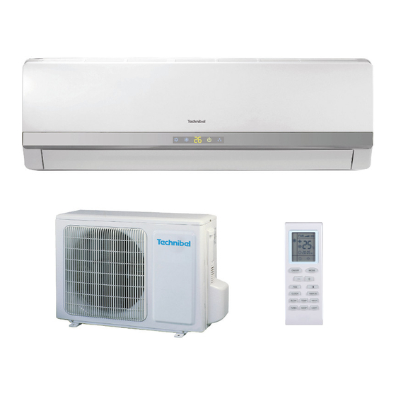
Technibel Climatisation MCAV92C5TA Installationsanleitungen
Multi zweirohrsystem-klimaanlage
Vorschau ausblenden
Andere Handbücher für MCAV92C5TA:
- Bedienungsanleitung (53 Seiten) ,
- Installationsanleitungen (27 Seiten) ,
- Bedienungsanleitung (11 Seiten)
Inhaltsverzeichnis
Werbung
Quicklinks
DECLARATION OF CONFORMITY
This product is marked
– Low voltage no. 73/23 EEC and 93/68 EEC.
– Electromagnetic compatibility no. 89/336 ECC, 92/31 EEC
and 93/68 EEC.
This declaration will become void in case of misuse and/or non
observance though partial of manufacturer's installation and/or
operating instructions.
COOLING ONLY MODELS
OPERATING LIMITS
Maximum conditions
Outdoor temperature : 43°C D.B.
Room temperature
: 32°C D.B. / 23°C W.B.
Minimum conditions
Outdoor temperature : 19°C D.B.
Room temperature
: 19°C D.B. / 14°C W.B.
HEAT PUMP MODELS
OPERATING LIMITS
Cooling Maximum conditions
Outdoor temperature : 43°C D.B.
Room temperature
: 32°C D.B. / 23°C W.B.
Cooling Minimum conditions
Outdoor temperature : 19°C D.B.
Room temperature
: 19°C D.B. / 14°C W.B.
Heating Maximum conditions
Outdoor temperature : 24°C D.B. / 18°C W.B.
Room temperature
: 27°C D.B.
Heating Minimum conditions
Outdoor temperature : –8°C D.B. / –9°C W.B.
ACCESSORIES SUPPLIED WITH THE UNIT
PARTS
FIGURE
Q.TY
RAWL PLUG
7
TAPPING
7
SCREW
REMOTE
1
CONTROL UNIT
- Multi Split system air conditioner -
as it satisfies Directives:
PARTS
FIGURE
Q.TY
AAA ALKALINE
2
BATTERY
AIR CLEAN
2
FILTER
37.4163.207.0
INSTALLATION INSTRUCTIONS
Model Combinations - 3 units -
Combine indoor and outdoor units only as listed below.
COOLING ONLY MODELS R22
Indoor Units
MCAV92C5TA- x 3
COOLING ONLY MODELS R407C
Indoor Units
MCAV92C5TA- x 3
CAV92C5TA- x 3
MCAV92C5TA- x 2
CAV92C5TA- x 1
CAV92C5TA- x 2
MCAV92C5TA- x 1
Power Supply:
Model Combinations - 4 units -
Combine indoor and out door units only as listed below.
COOLING ONLY MODELS R22
Indoor Units
MCAV92C5TA- x 4
COOLING ONLY MODELS R407C
Indoor Units
MCAV92C5TA- x 4
CAV92C5TA- x 4
MCAV92C5TA- x 2
CAV92C5TA- x 2
MCAV92C5TA- x 3
CAV92C5TA- x 1
CAV92C5TA- x 3
MCAV92C5TA- x 1
Power Supply:
Tools required for installation (not supplied)
11. Standard screwdriver
12. Phillips head screwdriver
13. Knife or wire stripper
14. Tape measure
15. Level
16. Sabre saw or key hole saw
17. Hacksaw
18. Core bits ø 5
19. Hammer
10. Drill
11. Tube cutter
12. Tube flaring tool
13. Torque wrench
14. Adjustable wrench
15. Reamer (for reburring)
16. Hex wrench
03/2002
Outdoor Units
GR227M3C5TA-
Outdoor Units
GRV227M3C5VA-
GRV227M3C5VA-
GRV227M3C5VA-
GRV227M3C5VA-
220 - 240 V ~ 50 Hz
Outdoor Units
GR227M3C5TA- +
DK5555C (DUAL KIT)
Outdoor Units
GRV227M3C5VA- +
DKR5555C (DUAL KIT)
GRV227M3C5VA- +
DKR5555C (DUAL KIT)
GRV227M3C5VA- +
DKR5555C (DUAL KIT)
GRV227M3C5VA- +
DKR5555C (DUAL KIT)
GRV227M3C5VA- +
DKR5555C (DUAL KIT)
220 - 240 V ~ 50 Hz
EG
I
F
D
E
Werbung
Inhaltsverzeichnis

Verwandte Anleitungen für Technibel Climatisation MCAV92C5TA


Inhaltszusammenfassung für Technibel Climatisation MCAV92C5TA
- Seite 1 – Low voltage no. 73/23 EEC and 93/68 EEC. Indoor Units Outdoor Units – Electromagnetic compatibility no. 89/336 ECC, 92/31 EEC MCAV92C5TA- x 3 GR227M3C5TA- and 93/68 EEC. This declaration will become void in case of misuse and/or non observance though partial of manufacturer's installation and/or COOLING ONLY MODELS R407C operating instructions.
- Seite 2 IMPORTANT! • Ground the unit following local electrical codes. • The Yellow/Green wire cannot be used for any connection Please read before installation different from the ground connection. • Connect all wiring tightly. Loose wiring may cause overheating This air conditioning system meets strict safety and operating at connection points and a possible fire hazard.
-
Seite 3: Electrical Data
Installation site selection - Indoor unit • Select a sufficiently strong location to support the weight of the AVOID unit. • Direct sunlight. • Select a location where tubing and drain hose have the shortest • Nearby heat sources that may affect unit performance. run to the outside. - Seite 4 – Compatibilità Elettromagnetica n. 89/336 CEE, 92/31 CEE Unità interne Unità esterne e 93/68 CEE. MCAV92C5TA- x 3 GR227M3C5TA- Questa dichiarazione sarà nulla nel caso di impiego diverso da quello dichiarato dal Fabbricante e/o di mancata MODELLI SOLO FREDDO R407C osservanza, anche solo parziale, delle istruzioni d'installazione e/o d'uso.
- Seite 5 IMPORTANTE! • Eseguire la messa a terra dell’unità secondo le norme elettriche locali. Leggere prima di iniziare l’installazione • Il conduttore giallo/verde non può essere utilizzato per collegamenti diversi dalla messa a terra. Questo sistema di condizionamento deve seguire rigidi standard •...
-
Seite 6: Dati Elettrici
Scelta del luogo di installazione unità interna • Verificare che il piano di appoggio sia sufficientemente resistente da EVITARE sostenere il peso dell’unità. • L’esposizione diretta al sole. • Scegliere una posizione in modo che la distanza tra le due unità sia •... -
Seite 7: Notice D'installation
– Compatibilité Electromagnétique n. 89/336 CEE, 92/31 Appareils intérieur Appareils extérieurs CEE et 93/68 CEE. MCAV92C5TA- x 3 GR227M3C5TA- Cette declaration sera nulle en cas d'une utilisation différente de celle déclarée par le Constructeur et/ou de la non- MODELES FROID SEUL R407C observation, même si partielle des instructions d'installation... - Seite 8 IMPORTANT! • Effectuez la mise à la terre de l'appareil en respectant les réglementations électriques locales. Veuillez lire ce qui suit avant de commencer • Le câble jaune/vert ne peut en aucun cas être utilisé pour toute Ce système de conditionnement de l'air répond à des normes autre connexion que celle de la mise à...
- Seite 9 Choix de l'emplacement d'installation - Appareil intérieur RECHERCHEZ • Un emplacement approprié à partir duquel l'ensemble de la pièce peut être EVITEZ climatisé de manière uniforme. • L'exposition directe au soleil. • Un emplacement suffisamment solide pour supporter le poids de l'appareil. •...
-
Seite 10: Mitgeliefertes Zubehör
NUR KÜHLUNG MODELLE R22 – Niederspannungsrichtilinie 73/23 EWG und 93/68 EWG. Innenraumgeräte Außengeräte – Elektromagnetische Verträglichkeit 89/336 EWG, 92/31 MCAV92C5TA- x 3 GR227M3C5TA- EWG und 93/68 EWG. Bei falschem Einsatz des Gerätes und/oder Nichtbeachtung auch nur von Teilen der Bedienungsanleitung und der NUR KÜHLUNG MODELLE R407C... - Seite 11 WICHTIG! Verbindungen unzureichende Erdung können Bitte vor Arbeitsbeginn lesen Unfallverletzungen oder Tod verursachen. • Erden Sie das Gerät gemäß den örtlich zutreffenden Vorschriften. Diese Klimaanlage entspricht strengen Sicherheits- und • Das Gelbe/Grüne Kabel ist für die ausschließliche Verwendung Betriebsnormen. als Erdleitung. Für den Installateur oder Bediener dieser Anlage ist es wichtig, sie •...
-
Seite 12: Zusätzliches Zubehör Für Die Aufstellung (Auf Anfrage)
Wahl des Installationsortes - Innenraumgerät • Wählen Sie eine Stelle, an der der Boden das Gewicht des Gerätes tragen VERMEIDEN SIE kann. • Direkte Sonneneinstrahlung. • Wählen Sie eine Stelle, von der aus die Rohre und der • Wärmequellen in der Nähe des Gerätes, die dessen Leistungsfähigkeit Wasserablaufschlauch den kürzesten Weg nach darußen haben. -
Seite 13: Instrucciones De Instalacion
– Baja Tensión n° 73/23 CEE y 93/68 CEE. Unidad interior Unidad exterior – Compatibilidad Electromagnetica n° 89/336 CEE, 92/31 CEE MCAV92C5TA- x 3 GR227M3C5TA- y 93/68 CEE. Esta declaración no tendrá efecto en sólo caso de que se haga un uso diferente al declarado por el Fabricante, y/o por MODELOS SOLO REFRIGERACION R407C el no respeto, incluso parcial, de las intrucciones de instalación... - Seite 14 ¡IMPORTANTE! • Realizar la puesta a tierra de la unidad siguiendo las normas eléctricas locales. Leer antes de empezar la instalación • El conductor amarillo/verde no se puede utilizar para conexiones que no sean la de tierra. Este sistema de acondicionamiento cumple medidas rígidas de •...
- Seite 15 Dónde instalar la unidad interior • Controlar que el lugar de apoyo es lo suficientemente resistente como EVITAR para soportar el peso de la unidad. • La exposición directa al sol. • Elegir una posición de modo que la distancia entre las dos unidades •...
- Seite 16 OUTDOOR UNIT • UNITÁ ESTERNA • UNITE EXTERIEUR • AUßENEINHEIT • UNIDAD EXTERIOR • UNIDADE EXTERIOR Minimum operation and maintenance area Area minima di esercizio e manutenzione. Surface minimum de fonctionnement et d’entretien. Raumbedarf des Gerätes. Area mínima de funcionamiento y manutención. Provide a solid base for outdoor unit raised from the ground level.
- Seite 17 Insert flare nuts removed from the units, then make a flare at the end of copper tubes. Cartellare le estremità dei tubi ricordandosi di infilare i bocchettoni rimossi dalle unità. Evaser les bouts des tubes, en se rappelant d'introduire les écrous enlevés des unités.
- Seite 18 SISTEMA MULTI-SPLIT A 3 UNITÀ / THREE UNITS MULTI-SPLIT SYSTEM / SYSTEME MULTI-SPLIT 3 UNITES SISTEMA MULTI-SPLIT DE 3 UNIDADES / 3 EINHEITEN MULTI-SPLIT SYSTEM Connect the tubes to the outdoor unit as shown.Tighten the connections with torque wrench. Follow the torque moment values shown in the table. INDOOR UNIT A Collegare i tubi all’unità...
- Seite 19 The service port on the wide tubes service valves uses a Schrader core valve to access the refrigerant system. Therefore, be sure to use a hose connector which has a push-pin inside. La valvola di servizio dei rubinetti dell'unità esterna da utilizzare per il vuoto del sistema, ripristino carica refrigerante e misurazione della pressione di esercizio è...
- Seite 20 Repeat the operations for the vacuum through a connection to the low pressure valve of the circuit "B" and then to the valve of the circuit "A". Ripetere le operazioni del vuoto collegandosi alla valvola di bassa pressione del circuito “B” quindi su quella del circuito “A”. Répéter les opérations du vide en se connectant à...
- Seite 21 Using an hexagonal key, open the valves of the small tube of the three circuits (circuit A, B and C), then close them after 10 seconds. Check tightness of all joints using liquid soap. Con una chiave esagonale, aprire le valvole del tubo piccolo dei tre circuiti (circuito A, B ed C) per soli 10 secondi.
- Seite 22 VERDE / GREEN WARNING VERT / VERDE PRASINO GRÜN / Be sure to turn the air conditioner OFF and disconnect the power before opening the outdoor unit. Disconnect the power, then replace the green and blue connectors of outdoor unit as shown. Replace the frontal panel of outdoor unit.
- Seite 23 SISTEMA MULTI-SPLIT A 3 UNITÀ / THREE UNITS MULTI-SPLIT SYSTEM / SYSTEME MULTI-SPLIT 3 UNITES / SISTEMA MULTI-SPLIT DE 3 UNIDADES 3 EINHEITEN MULTI-SPLIT SYSTEM POWER SUPPLY 220 - 240 V~ 50 Hz INDOOR UNIT TP 7P TP 8P OUTDOOR UNIT DELAYED FUSE TRÄGE SICHERUNG FUSIBILE RITARDATO...
- Seite 24 SISTEMA MULTI-SPLIT A 3 UNITÀ / THREE UNITS MULTI-SPLIT SYSTEM / SYSTEME MULTI-SPLIT 3 UNITES SISTEMA MULTI-SPLIT DE 3 UNIDADES / 3 EINHEITEN MULTI-SPLIT SYSTEM PUMP DOWN Pump down means collecting all refrigerant gas in the system back into Das bedeutet: das Kühlmittel in die Außeneinheit ohne Gas-Verlust the outdoor unit without losing gas.
- Seite 25 Connect a valve manifold to the charge port on the wide tube service valve and open it partially (1/4 of a turn). Turn the narrow tube service valve all the way. Collegare un gruppo manometrico alla valvola della bassa pressione del circuito C, aprirla parzialmente (1/4 di giro).
- Seite 26 Turn on the unit operating switch and start cooling operation. When the low- pressure gauge reading falls to a value between 1 and 0,5 Kg/cm2, fully close the wide tube stern and then quickly turn off the unit. Avviare il condizionatore in raffreddamento. Quando la pressione letta sul manometro scende ad un valore compreso tra 1 e 0,5 Kg/cm2, chiudere completamente la valvola bassa pressione e spegnere il condizionatore.
- Seite 27 SISTEMA MULTI-SPLIT A 4 UNITÀ / FOUR UNITS MULTI-SPLIT SYSTEM / SYSTEME MULTI-SPLIT 4 UNITES SISTEMA MULTI-SPLIT DE 4 UNIDADES / 4 EINHEITEN MULTI-SPLIT SYSTEM Remove the capillary box from the outdoor unit. Rimuovere la scatola capillare dall’unità esterna. Enlever la boîte capillaire de l'unité extérieure. Das Kapillargehäuse von der Außeneinheit entfernen.
- Seite 28 Connect the tubes to the outdoor unit as shown.Tighten the connections with torque wrench. Follow the torque moment values shown in the table. Collegare i tubi all’unità esterna come raffigurato. Stringere le connessioni con una chiave dinamometrica; attenersi alla tabella valori momento torcente. Connecter les tubes à...
- Seite 29 The service port on the wide tubes service valves uses a Schrader core valve to access the refrigerant system. Therefore, be sure to use a hose connector which has a push-pin inside. La valvola di servizio dei rubinetti dell'unità esterna da utilizzare per il vuoto del sistema, ripristino carica refrigerante e misurazione della pressione di esercizio è...
- Seite 30 Repeat the operations for the vacuum through a connection with only one tube of vacuum pump to the low pressure valve of the circuit "B" and then to the valve of the circuit "A". Ripetere le operazioni del vuoto collegandosi con un solo tubo della pompa del vuoto prima alla valvola bassa pressione del circuito “B”, quindi su quella del circuito “A”.
- Seite 31 Using an hexagonal key, open the valves of the small tubes of the three circuits (circuit A, B and C), then close them after 10 seconds. Check tightness of all joints using liquid soap (for all circuits). Con una chiave esagonale, aprire le valvole dei tubi piccoli dei tre circuiti per soli 10 secondi (circuito A, B e C).
- Seite 32 WARNING VERDE / GREEN VERDE / GREEN VERT / VERDE / GRÜN VERT / VERDE / GRÜN Be sure to turn the air conditioner OFF and disconnect the power before opening the unit. Disconnect the power, then replace the green and blue connectors of outdoor unit and of dual-kit as shown.
- Seite 33 Complete insulation of refrigerant tubes; wrap with armoning tape. Fix and support tubes with brackets. Seal hole in the wall. Completare l'isolamento, proteggere con nastratura, fissare e supportare con staffe; se necessario sigillare il foro di passaggio nel muro. Compléter l'isolation, protéger avec des rubans, fixer et appuyer sur de brides;...
-
Seite 34: Indoor Unit
SISTEMA MULTI-SPLIT A 4 UNITÀ / FOUR UNITS MULTI-SPLIT SYSTEM / SYSTEME MULTI-SPLIT 4 UNITES SISTEMA MULTI-SPLIT DE 4 UNIDADES / 4 EINHEITEN MULTI-SPLIT SYSTEM POWER SUPPLY 220 - 240 V 50 Hz INDOOR UNIT TP 7P TP 8P OUTDOOR UNIT DUAL KIT DELAYED FUSE TRÄGE SICHERUNG... - Seite 35 Supply power wire A: Multipolar electric wire. Size and length of the suggested electric wire are showed on table “electrical data”. The wire must be Mod. H07RN-F (according to CEI 20-19 CENELEC HD 22). Make sure the length of the conductors between the fixing point and the terminals allows the straining of the conductors L, N before that of the grounding.
- Seite 36 SISTEMA MULTI-SPLIT A 4 UNITÀ / FOUR UNITS MULTI-SPLIT SYSTEM / SYSTEME MULTI-SPLIT 4 UNITES SISTEMA MULTI-SPLIT DE 4 UNIDADES / 4 EINHEITEN MULTI-SPLIT SYSTEM PUMP DOWN Pump down means collecting all refrigerant gas in the system back into Das bedeutet: das Kühlmittel in die Außeneinheit ohne Gas-Verlust the outdoor unit without losing gas.
- Seite 37 Connect a valve manifold to the charge port connecting to dual-kit. Open it partly (1/4 turn). Purge the air from manometer. Turn the narrow tube service valve connecting the dual-kit (circuit C1-C2) all the way. Collegare un gruppo manometrico alla valvola bassa pressione di collegamento al dual kit. Aprirla parzialmente (1/4 di giro) e spurgare l’aria dal manometro.
- Seite 38 Connect a valve manifold to the charge port of circuit "B". Open it partly (1/4 turn). Purge the air from manometer. Turn the narrow tube service valves of the circuit B and A all the way. Collegare un gruppo manometrico alla valvola bassa pressione del circuito B. Aprirla parzialmente (1/4 di giro) e spurgare l’aria dal manometro.
- Seite 39 WARNING VERDE / GREEN VERDE / GREEN VERT / VERDE / GRÜN VERT / VERDE / GRÜN Be sure to turn the air conditioner OFF and disconnect the power before opening the unit. Remove the valve manifold. At that time PUMP DOWN has been completed and all regrigerant gas will have been collected in the outdoor unit.
- Seite 40 BASIC FUNCTIONS OF THE SERVICE VALVES • FUNZIONI PRINCIPALI DELLE VALVOLE • FONCTIONS DE BASE DE VALVES DE SERVICE • FUNKTION DER ABSPERRVENTILE • PRINCIPALES FUNCIONES DE LAS VALVULAS Narrow tube service Action Wide tube service valve (3-way) valve (2-way) Valve cap CLOSED Shipping...
- Seite 41 TEST RUN • COME ESEGUIRE LA PROVA DEL CONDIZIONATORE (TEST RUN) • CONTROLE FINALE • ENDKONTROLLE • COMO REALIZAR LA PRUEBA DEL ACONDICIONADOR (TESTRUN) TEST Cooling mode Heating mode Switch on the power source. Press the ON/OFF button and change to heating Switch on the power source.
- Seite 42 Electric wiring diagrams’ symbols / Simboli schemi elettici / Symboles des schemas électriques Symbole der System-Schaltplanen / Símbolos de los esquemas eléctricos SYMBOL CRANK CASE HEATER RISCALDATORE CARTER CHAUFFAGE DE CARTER-MOTEUR KURBELGEHÄUSEHEIZUNG CALENTADOR DEL CÁRTER COMPRESSOR MOTOR MOTORE COMPRESSORE MOTEUR DE COMPRESSEUR KOMPRESSORMOTOR MOTOR DEL COMPRESOR C1, 2, 3...
- Seite 43 In order to carry on a constant improvement, our products can be modified without prior notice. Per garantire un costante miglioramento dei nostri prodotti, ci riserviamo di modificarli senza preavviso. Par souci d’amélioration constante, nos produits peuvent être modifiés sans préavis. Unsere Produkte werden laufend verbessert und können Vorankündigung abgeändert Werden.