Herunterladen Inhalt Inhalt Diese Seite drucken

Telcoma ZEN 100E Bedienungsanleitung

Schleppautomation für sektional- und kipptore.

Werbung

Verfügbare Sprachen
  • DE

Verfügbare Sprachen

  • DEUTSCH, seite 66
I
AUTOMAZIONE PER PORTE SEZIONALI E BASCULANTI.
F
AUTOMATISATION PAR ENTRAÎNEMENT POUR PORTES SECTIONNELLES ET BASCULANTES.
E
AUTOMATISMO PARA PUERTAS SECCIONALES Y BASCULANTES.
GB
AUTOMATION FOR SECTIONAL AND UP-AND-OVER DOORS.
D
SCHLEPPAUTOMATION FÜR SEKTIONAL- UND KIPPTORE.
NL
TREKAUTOMATISERING VOOR SECTIONAAL- EN KANTELDEUREN.
Telcoma srl - Via L. Manzoni, 11 - Z.I. Campidui - 31015 Conegliano (TV) Italy
Tel. +39 0438451099 - Fax +39 0438451102 - Part. IVA 00809520265
ZEN 100E
ZEN 60E
http://www.telcoma.it
V. 06.2010
E-mail: info@telcoma.it
ISTZENE
1

Werbung

Inhaltsverzeichnis
loading

Inhaltszusammenfassung für Telcoma ZEN 100E

  • Seite 1 AUTOMATION FOR SECTIONAL AND UP-AND-OVER DOORS. SCHLEPPAUTOMATION FÜR SEKTIONAL- UND KIPPTORE. TREKAUTOMATISERING VOOR SECTIONAAL- EN KANTELDEUREN. Telcoma srl - Via L. Manzoni, 11 - Z.I. Campidui - 31015 Conegliano (TV) Italy Tel. +39 0438451099 - Fax +39 0438451102 - Part. IVA 00809520265 http://www.telcoma.it...
  • Seite 2: Modelli E Caratteristiche

    24Vdc con encoder, forza di trazione max 600 N. Centralina e luce di cortesia incorporata. ZEN 100E: Motoriduttore elettromeccanico irreversibile, per uso residenziale, motore 24Vdc con encoder, forza di trazione max 1000 N. Centralina e luce di cortesia incorporata.
  • Seite 3: Caratteristiche Tecniche

    CARATTERISTICHE TECNICHE ZEN 60E ZEN 100E Alimentazione motore 24 Vdc 24 Vdc Superficie max. porta 12 m Tempo di apertura 20 sec 20 sec Corrente max. assorbita (a 230Vac) 1.1 A 1.2 A Potenza massima assorbita 230 W 260 W Corrente max.
  • Seite 4 Il fabbricante: Telcoma srl via L. Manzoni, 11 - 31015 - Z.I. Campidui Conegliano (TV) - ITALY DICHIARA che i prodotti: MOTORIDUTTORE ZEN 60E e MOTORIDUTTORE ZEN 100E sono conformi alle seguenti direttive CEE: -Direttiva EMC 2004/108/CE in riferimento alle seguenti normative: EN 55014-1;...
  • Seite 5 MONTAGGIO GUIDA DI TRASMISSIONE In caso siate in possesso di profili modulari da 1060 mm o da 1600 mm, procedere all’assemblaggio della guida come indicato in procedura: - Predisporsi su uno spazio utile ad ospitare la guida nella sua totalità. - Allentare il dado D e sfilare supporto di rinvio F (fig.2).
  • Seite 6: Installazione

    INSTALLAZIONE SEZIONALE: fissare la guida di trasmissione al centro della porta sezionale, direttamente sopra il palo molla usando dei tasselli e viti adeguati. Consigliamo l’installazione della guida, circa a 40mm sopra il passaggio del portone sezionale (fig. 7 e 8). Livellare la guida e bloccarla con i supporti guida e relative staffe (fig.9). Fissare con delle viti adeguate la staffa attacco anta all’estremità...
  • Seite 7 Fig. 13 CENTRALE ELETTRONICA Z124 Le automazioni ZEN 100E e ZEN 60E hanno a bordo una scheda comando modello Z124, da questa partono tutte le connessioni elettriche (motore, encoder, alimentazione, ecc.) ha un connettore per un ricevitore radio mod. OC (optional) e un morsetto a vite per la lampada di cortesia.
  • Seite 8 DESCRIZIONE DELLE PARTI (fig. 14) 1) Morsettiera collegamenti a 230 V (linea, primario trasformatore e lampeggiante) 2) Fusibile linea T2A 230V 3) Fusibile alimentazione T10A 24V 4) Morsettiera collegamenti motore, 24V e secondario trasformatore (22V) 5) Morsettiera per luce cortesia 12V 10W 6) Connettore collegamento encoder 7) Connettore per scheda radio opzionalemod.
  • Seite 9: Collegamenti Elettrici

    COLLEGAMENTI ELETTRICI Per i collegamenti seguire le tabelle 1 e 2 e la figura 15. Nel caso di impianti già esistenti è opportuno un controllo generale dello stato dei conduttori (sezione, isolamento, contatti) e delle apparecchiature ausiliarie (fotocellule, riceventi, pulsantiere, selettori chiave, ecc.). 1) Per l’alimentazione usare il cavo in dotazione 2x0,75 mm con spina.
  • Seite 10 TAB. 2 Antenna c.c. 11 10 c.c. c.c. 2 3 4 Z124 230V 230V Lampeggiante 50Hz 230V max. 100W (cambio funzione con dip n. 3 e 4) Fig. 15 impulso 1” 230V max. 100W (dip n. 3 ON e 4 OFF) Fig.
  • Seite 11 MANOVRA DI POSIZIONAMENTO DELLA PORTA Con questa procedura possiamo manovrare a piacere la porta collegata al motoriduttore, con lo scopo di preparare l’impianto per la programmazione e per capire se il motoriduttore è collegato correttamente. ✓ Durante questa operazione i pulsanti funzionano in modo “uomo presente” e le sicurezze vengono ignorate. Procedura: 1) Tenendo premuto il pulsante PROG.
  • Seite 12 NOTA: Se dopo l’autoapprendimento si portano i DIP 6 e 9 in ON, il tempo di pausa avrà un default di 30sec. e il rallentamento in chiusura avrà un valore impostato da Telcoma , non sarà presente il rallentamento in apertura (per impostarlo seguire...
  • Seite 13 Programmazione avanzata - Dip 6 e DIP 9 in posizione ON Tempo di pausa e rallentamenti programmabili 1) tenere premuto pulsante STOP/PROG finché il led LD1 si accende, 5 sec circa. 2) premere pulsante PP, il motore apre e raggiunge il fermo – FIG.2A. 3) attendere il tempo di pausa desiderato, quindi premere di nuovo PP, il motore richiude.
  • Seite 14 FIG.1 FERMO IN CHIUSURA - FIG.1 A...
  • Seite 15 FIG.2 FERMO IN APERTURA - FIG.2 A...
  • Seite 16: Regolazione Potenza

    IMPOSTAZIONE FUNZIONI (tab. 3) Le varie opzioni descritte sono selezionabili con il dip-switch funzioni (part. 19 di fig.14). - Si tenga presente che per far apprendere una variazione delle impostazioni alla centrale dobbiamo togliere e ridare l’alimentazione, oppure cortocircuitare per un attimo i 2 pin di reset della centralina. TAB.
  • Seite 17 RICEVENTE AD INNESTO mod. OC (opzionale) Le riceventi sono ad auto-apprendimento e possono memorizzare più codici nello stesso canale. Le funzioni dei due canali radio sono: Canale 1 Passo/Passo Canale 2 n.c. Per memorizzare i trasmettitori procedere come segue: - Inserire la ricevente nel connettore (particolare 7 di fig. 14) - Alimentare la centrale e attendere che i led sulla ricevente si spengano.
  • Seite 18: Modèles Et Caractéristiques

    24 Vcc avec encodeur, force de traction max. 600 N. Logique de commande et éclairage automatique incorporés. ZEN 100E: Opérateur électromécanique irréversible, pour usage résidentiel, moteur 24 Vcc avec encodeur, force de traction max. 1000 N. Logique de commande et éclairage automatique incorporés.
  • Seite 19: Caractéristiques Techniques

    CARACTÉRISTIQUES TECHNIQUES ZEN 60E ZEN 100E Alimentation moteur 24 Vdc 24 Vdc Surface max. porte 12 m Temps d’ouverture 20 sec 20 sec Courant max. absorbé (à 230 Vca) 1,1 A 1,2 A Puissance max absorbée 230 W 260 W Courant max.
  • Seite 20: Déclaration De Conformité Ce

    Le fabricant : Telcoma srl Via L. Manzoni 11, Z.I. Campidui - 31015 Conegliano (TV) ITALIE, DÉCLARE que les produits : OPÉRATEUR ZEN 60E et OPÉRATEUR ZEN 100E sont conformes aux directives CEE suivantes : -Directive CEM 2004/108/CE en référence aux normes suivantes : EN 55014-1 ;...
  • Seite 21 MONTAGE RAIL DE TRANSMISSION Si vous êtes en possession de rails modulaires de 1060 mm ou de 1600 mm, procéder à l’assemblage du rail comme l’indique la procédure. - Préparer un espace utile en mesure d’accueillir le rail dans sa totalité. - Desserrer l’écrou D et extraire le support de renvoi (fig.
  • Seite 22: Installation

    INSTALLATION PORTE SECTIONNELLE: fixer le rail de transmission au centre de la porte sectionnelle, directement au dessus de la tige ressort en utilisant des chevilles et des vis appropriées. Nous conseillons l’installation du rail, à environ 40 mm au-dessus du passage de la porte sectionnelle (fig. 7 et 8). Mettre le rail de niveau et le bloquer avec les supports et les pattes de fixation (fig.
  • Seite 23 Fig. 13 LOGIQUE DE COMMANDE ÉLECTRONIQUE Z124 Les automatismes ZEN 100E et ZEN 60E sont équipés d’une carte de commande modèle Z124, d’où partent toutes les connexions électriques (moteur, encodeur, alimentation, etc.) ; la carte a un connecteur pour un...
  • Seite 24 DESCRIPTION DES PARTIES (fig. 14) 1) Bornier connexions à 230 V (ligne, primaire transformateur et clignotant) 2) Fusible ligne T2A 230 V 3) Fusible alimentation T10A 24V 4) Bornier connexions moteur, 24 V et secondaire transformateur (22 V) 5) Bornier pour éclairage automatique 12 V 10 W 6) Connecteur pour encodeur 7) Connecteur pour carte radio en option mod.
  • Seite 25: Branchements Électriques

    BRANCHEMENTS ÉLECTRIQUES Pour les connexions suivre les tableaux 1 et 2 et la figure 15. Dans le cas d’installations pré-existantes il est opportun d’effectuer un contrôle général de l’état des conducteurs (section, isolement, contacts) et des appareils auxiliaires (photocellules, récepteurs, claviers de commande, sélecteurs à clé, etc.). 1) Pour l’alimentation utiliser le câble fourni 2x0,75 mm avec fiche.
  • Seite 26 TAB. 2 Connexion de barre palpeuse contact Normalement Fermé Connexion de barre palpeuse contact Normalement Ouvert selon la norme EN 12978 Entrée non utilisée. Connecter la borne 11 avec la 10 et mettre le dip n. 10 sur OFF Antenna c.c.
  • Seite 27 MANEUVRE DE POSITIONNEMENT DE LA PORTE Avec cette procédure on peut manœuvrer à volonté la porte connectée à l’opérateur, dans le but de préparer l’installation pour la programmation et pour comprendre si l’opérateur est connecté correctement. Durant cette opération les touches fonctionnent en mode « commande à action maintenue » et les sécurités sont souvent ignorées. ✓...
  • Seite 28 NOTE : Si après l’auto-apprentissage on met les dip-switchs 6 et 9 sur ON, par défaut le temps de pause sera de 30 s et le ralentissement en fermeture aura une valeur fixée par Telcoma, il n’y aura pas de ralentissement en ouverture (pour le...
  • Seite 29 Programmation avancée - Dip-switchs 6 et 9 sur ON Temps de pause et ralentissements programmables 1) maintenir le bouton STOP/PROG enfoncé jusqu’à ce que la led LD1 s’allume, 5 secondes environ. 2) presser la touche PP, le moteur ouvre et atteint la butée – FIG.2A. 3) attendre le temps de pause désiré, puis presser de nouveau PP, le moteur referme.
  • Seite 30 FIG.1 BUTÉE EN FERMETURE – FIG.1A...
  • Seite 31 FIG.2 BUTÉE EN OUVERTURE – FIG.2A...
  • Seite 32: Réglage De La Puissance

    SÉLECTION DES FONCTIONS (tab. 3) Les différentes options décrites sont sélectionnables avec le dip-switch fonctions (pos. 19 - fig.14). - Il faut se souvenir que pour que la logique enregistre une variation des sélections, il faut couper un instant l’alimentation électrique puis la rétablir, ou bien il faut court-circuiter un instant les 2 broches de réinitialisation de la logique.
  • Seite 33: Avertissements Importants Concernant L'installation

    RÉCEPTEUR EMBROCHABLE mod. OC (option) Les récepteurs sont à auto-apprentissage et peuvent mémoriser plus de codes dans le même canal. Les fonctions des deux canaux radio sont : Canal 1 Pas à pas Canal 2 N.F. Pour mémoriser les émetteurs, procéder comme suit : - Monter le récepteur dans le connecteur (pos.
  • Seite 34: Modelos Y Características

    24Vdc con encoder, fuerza de tracción máx. 600 N. Central y luz de cortesía incorporada. ZEN 100E: Motorreductor electromecánico irreversible, para uso residencial, motor de 24Vdc con encoder, fuerza de tracción máx. 1000 N. Central y luz de cortesía incorporada.
  • Seite 35: Características Técnicas

    CARACTERÍSTICAS TÉCNICAS ZEN 60E ZEN 100E Alimentación del motor 24 Vdc 24 Vdc Superficie máx. puerta 12 m Tiempo de apertura 20 sec 20 sec Corriente máx. absorbida (a 230VAC) 1.1 A 1.2 A Potencia máx. absorbida 230 W 260 W Corriente máx.
  • Seite 36: Declaración De Conformidad Ce

    El fabricante: Telcoma srl Via L. Manzoni, 11 - 31015 - Z.I. Campidui Conegliano (TV) - ITALIA DECLARA que los productos: MOTORREDUCTOR ZEN 60E y MOTORREDUCTOR ZEN 100E son conformes a las siguientes directivas CEE: -Directiva CEM 2004/108/CE con relación a las siguientes normativas: EN 55014-1;...
  • Seite 37 MONTAJE DE LA GUÍA DE TRANSMISIÓN Si usted tuviera los perfiles modulares de 1060 mm o de 1600 mm, proceda con el ensamblaje de la guía tal como indicado en el procedimiento: - Colóquese sobre un espacio útil para apoyar la guía en su totalidad. - Afloje la tuerca D y extraiga el soporte de reenvío F (fig.2).
  • Seite 38: Instalación

    INSTALACIÓN SECCIONAL: fije la guía de transmisión en el centro de la puerta seccional, directamente sobre el tubo del muelle, utilizando tacos y tornillos adecuados. Se aconseja instalar la guía a unos 40 mm por encima del paso del portón seccional (figs. 7 y 8). Nivele la guía y bloquéela con los soportes de la guía y con los estribos suministrados (fig.9).
  • Seite 39 Fig. 13 CENTRAL ELECTRÓNICA Z124 Las automatizaciones ZEN 100E y ZEN 60E incorporan una tarjeta de mando modelo Z124, desde la cual salen todas las conexiones eléctricas (motor, encoder, alimentación, etc.); incorpora un conector para un radiorreceptor mod. OC (opcional) y un borne de tornillo para la luz de cortesía.
  • Seite 40 DESCRIPCIÓN DE LAS PIEZAS (fig. 14) 1) Regleta de conexión de 230 V (línea, primario del transformador y luz intermitente) 2) Fusible de línea T2A 230V 3) Fusible de alimentación T10A 24V 4) Regleta de conexión del motor 24V y secundario del transformador (22V) 5) Regleta para la luz de cortesía 12V 10W 6) Conector para el encoder 7) Conector para la tarjeta radio opcional mod.
  • Seite 41: Conexiones Eléctricas

    CONEXIONES ELÉCTRICAS Para las conexiones observe las tablas 1 y 2 y la figura 15. En el caso de instalaciones ya montadas, es oportuno realizar un control general de las condiciones de los conductores (sección, aislamiento, contactos) y de los equipos auxiliares (fotocélulas, receptores, botoneras, selectores de llave, etc.). 1) Para la alimentación utilice el cable entregado 2x0,75 mm con enchufe.
  • Seite 42 TAB. 2 Conexión de banda con contacto Normalmente Cerrado Conexión de banda con contacto Normalmente Abierto De conformidad con la normativa EN 12978 Entrada no utilizada. Conecte el borne 11 con el 10 y coloque el dip n° 10 en OFF Antenna c.c.
  • Seite 43 MANIOBRA DE POSICIONAMIENTO DE LA PUERTA Con este procedimiento se puede maniobrar a placer la puerta conectada al motorreductor a fin de preparar la instalación para la programación y para saber si el motorreductor está conectado correctamente. Durante esta operación los botones funcionan en modo “hombre presente” y los dispositivos de seguridad están inhibidos. ✓...
  • Seite 44 NOTA: si después del autoaprendizaje se colocan los DIP 6 y 9 en ON, el tiempo de pausa será por defecto de 30 seg. y la desaceleración durante el cierre tendrá un valor configurado por Telcoma, no estará habilitada la desaceleración durante...
  • Seite 45 Programación avanzada - Dip 6 y DIP 9 en posición ON Tiempo de pausa y desaceleraciones programables 1) mantenga pulsado el botón STOP/PROG hasta que se encienda el led LD1, alrededor de 5 segundos. 2) pulse el botón PP, el motor realizará el movimiento de apertura y llegará al tope – FIG.2A. 3) espere el tiempo de pausa deseado y pulse de nuevo PP, el motor realizará...
  • Seite 46 FIG.1 TOPE DE CIERRE – FIG.1A...
  • Seite 47 FIG.2 TOPE DE ABERTURA – FIG.2A...
  • Seite 48: Regulación De La Potencia

    CONFIGURACIONES DE LAS FUNCIONES (tab. 3) Las diferentes opciones descritas se seleccionan con el dip-switch funciones (detalle 19 de fig.14) - Tenga en cuenta que para que la central aprenda una modificación de las configuraciones habrá que cortar y activar la alimentación, o bien cortocircuitar por un instante los 2 contactos de reajuste de la central. TAB.
  • Seite 49 RECEPTOR ENCHUFABLE modelo OC (opcional) Los receptores son de autoaprendizaje y pueden memorizar varios códigos en el mismo canal. Las funciones de dos canales radio son: Canal 1 Paso a paso Canal 2 NC Para memorizar los transmisores, proceda de la siguiente manera: - Conecte el receptor al conector (detalle 7 de fig.
  • Seite 50 24 Vdc motor with encoder, maximum traction force 600 N. Control unit and built-in courtesy light. ZEN 100E: Irreversible electromechanical gearmotor, for residential use, 24 Vdc motor with encoder, maximum traction force 1000 N. Control unit and built-in courtesy light.
  • Seite 51: Technical Specifications

    TECHNICAL SPECIFICATIONS ZEN 60E ZEN 100E Motor power supply 24 Vdc 24 Vdc Max. door surface area 12 m Opening time 20 sec 20 sec Max. current absorption (at 230Vac) 1.1 A 1.2 A Max absorbed power 230 W 260 W Max.
  • Seite 52: Ce Declaration Of Conformity

    The manufacturer: Telcoma srl via L. Manzoni, 11 - 31015 - Z.I. Campidui Conegliano (TV) - ITALY DECLARES that the products: GEARMOTOR ZEN 60E and GEARMOTOR ZEN 100E comply with the following EC directives: -EMC Directive 2004/108/CE with reference to the following standards: EN 55014-1;...
  • Seite 53 TRANSMISSION GUIDE ASSEMBLY In the case of 1060mm or 1600mm modular profiles, assemble the guide as specified in the procedure. - Prepare an adequate area to hold the entire guide. - Loosen nut D and remove the drive support F (fig. 2) - Rotate the assembled guides with chain/belt to form a single profile.
  • Seite 54: Installation

    INSTALLATION SECTIONAL DOOR: fix the transmission guide at the centre of the sectional door, directly above the spring post using suitable screws and plugs. The guide should ideally be installed at approx. 40 mm. above the section door transit area (fig. 7 and 8). Level the guide and lock by means of the guide supports and relative brackets (fig.9). Fix the leaf connection bracket at the highest end of the door.
  • Seite 55 Z124 ELECTRONIC CONTROL UNIT The automations ZEN 100E and ZEN 60E are equipped on board with a control board model Z124, from which all electrical connections are made (motor, encoder, power supply, etc.) with a connector for a radio receiver mod.
  • Seite 56 PART DESCRIPTION (fig. 14) 1) 230 V connection terminal board (line, primary transformer and flashing light) 2) T2A 230V line fuse 3) T10A 24V power fuse 4) Motor connection terminal board, 24 V and secondary transformer (22V) 5) Terminal board for courtesy light 12V 10W 6) Encoder connector 7) Connector for optional radio receiver mod.
  • Seite 57: Electrical Connections

    ELECTRICAL CONNECTIONS For connections, refer to tables 1 and 2 and figure 15. In the case of existing systems a general check should be made of the condition of wiring (section, insulation, contacts) and auxiliary equipment (photocells, receivers, pushbutton panels, key-operated switches etc.). 1) For power supply, use the 2x0,75 mm cable with plug supplied.
  • Seite 58 TAB. 2 Connection of edge with Normally closed contact Connection of edge with Normally open contact In compliance with standard EN 12978 Input not used. Connect terminal 11 with terminal 10 and set dip-switch no. 10 to OFF Antenna c.c. 11 10 c.c.
  • Seite 59 DOOR POSITIONING MANOEUVRE This procedure enables manoeuvring as required of the door connected to the gearmotor, to prepare the system for programming and to check gearmotor connections. During this operation, the pushbuttons work in “hold-to-run” mode and safety devices are ignored. ✓...
  • Seite 60 NOTE: If the dipswitches 6 and 9 are set to ON after self-learning, the pause time will have a default value of 30 sec. while deceleration during closure will have a value set by Telcoma , (there will be no deceleration on opening; to set, refer to the...
  • Seite 61 Advanced programming - Dip 6 and DIP 9 set to ON Programmable pause and deceleration times 1) Hold down the STOP/PROG button for about 5 seconds until LED LD1 lights up. 2) Press the PP button: the motor will open as far as the opening stop – FIG. 2A. 3) Wait for the required pause interval, then press PP again: the motor now performs the closure movement.
  • Seite 62 FIG.1 CLOSURE STOP – FIG. 1A...
  • Seite 63 FIG.2 OPENING STOP – FIG. 2A...
  • Seite 64 FUNCTION SETTINGS (table 3) The various options described can be selected by means of the function dip-switch (detail 19 of fig.14). - Bear in mind that to ensure that the control unit “learns” a variation to settings, it must be switched off and on again;...
  • Seite 65 COUPLING TYPE RECEIVER mod. OC (optional) The receivers are “self-learn” type and can memorise several codes on the same channel. The functions of the two radio channels are: Channel 1 Step/step Channel 2 N.O. To memorise the transmitters proceed as follows: - Insert the receiver in the connector (detail 7 of fig.
  • Seite 66: Modelle Und Merkmale

    ZEN 60E: Elektromechanischer, selbsthemmender Antrieb für den Einsatz an Wohngebäuden, 24Vdc Motor mit Encoder, max. Zugkraft 600 N. Steuerung und eingebautes Zusatzlicht. ZEN 100E: Elektromechanischer, selbsthemmender Antrieb für den Einsatz an Wohngebäuden, 24Vdc Motor mit Encoder, max. Zugkraft 1000 N. Steuerung und eingebautes Zusatzlicht.
  • Seite 67: Technische Merkmale

    TECHNISCHE MERKMALE ZEN 60E ZEN 100E Versorgung des Motors 24 Vdc 24 Vdc Höchstfläche des Tors 12 m Öffnungszeit 20 sec 20 sec Max. aufgenommener Strom (bei 230Vac) 1.1 A 1.2 A Max. Leistungsaufnahme 230 W 260 W Max. Motorstromaufnhame (24V) Betriebstemperatur -10 +70°C...
  • Seite 68: Ce-Konformitätserklärung

    5) Antriebsarm 10) Versorgungslinie (230Vac) CE-KONFORMITÄTSERKLÄRUNG Der Hersteller Telcoma srl via L. Manzoni, 11 - 31015 - Z.I. Campidui Conegliano (TV) - ITALY ERKLÄRT, dass die Produkte: ANTRIEB ZEN 60E und ANTRIEB ZEN 100 Den folgenden CEE-Richtlinien entsprechen: Richtlinie EMC 2004/108/CE in Bezug auf die folgenden Vorschriften: EN 55014-1;...
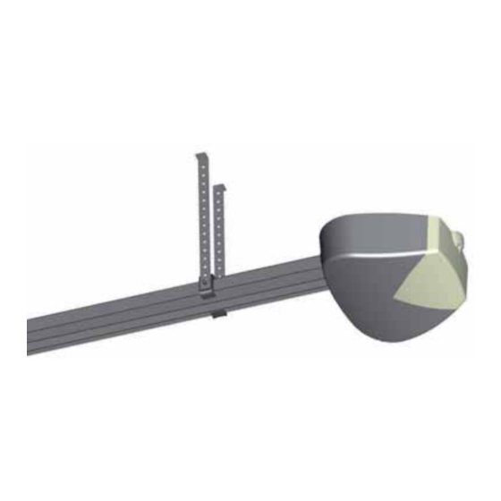
  • Seite 69: Montage Der Führung

    MONTAGE DER FÜHRUNG Falls Sie über modulare Profile L. 1060 mm oder 1600 mm verfügen, die Führung wie folgend zusammenbauen. - Einen für die gesamte Führung genügend großen Freiraum vorbereiten - Die Mutter D lockern Vorgelegehalterung F ziehen (Abb. 2) - Die mit Kette/Riemen zusammengebauten Führungen so drehen, dass sie ein einziges Profil bilden.
  • Seite 70 INSTALLATION SEKTIONALTOR: die Führung mit entsprechenden Dübeln und Schrauben in der Mitte des Sektionaltors direkt über der Federstange befestigen. Wir raten, die Führung ca. 40 mm über dem Durchgang des Sektionaltors zu installieren (Abb. 7 und 8). Die Führung nivellieren und mit den Halterungen und den entsprechenden, mitgelieferten Bügeln blockieren (Abb.
  • Seite 71: Elektronische Steuerung Z124

    Abb. 13 ELEKTRONISCHE STEUERUNG Z124 In den Automationen ZEN 100E und ZEN 60E befindet sich eine Steuerkarte Modell Z124, von der alle elektrischen Anschlüsse ausgehen (für Antrieb, Encoder, Versorgung, usw.); sie verfügt über einen Verbinder für einen Funkempfänger Mod. OC (Optional) und eine Schraubklemme für das Zusatzlicht.
  • Seite 72: Dbeschreibung Der Teile (Abb. 14)

    BESCHREIBUNG DER TEILE (Abb. 14) 1) Klemmleiste für die 230 V Anschlüsse (Linie, Primärkreis des Transformators und Blinklicht) 2) Liniensicherung T2A 230V 3) Sicherung der Versorgung T10A 24V 4) Klemmleiste für die Anschlüsse des Antriebs, 24V und Sekundärkreis des Transformators (22 V) 5) Klemmleiste für das Zusatzlicht 12V 10W 6) Verbinder für den Anschluss des Encoders 7) Verbinder für die Funkkarte Mod.
  • Seite 73: Elektrische Anschlüsse

    ELEKTRISCHE ANSCHLÜSSE Für die Anschlüsse, nach den Tabellen 1 und 2 und der Abbildung 15 vorgehen. Im Fall bereits existierender Anlagen sollte eine Generalkontrolle des Zustandes der Leiter (Querschnitt, Isolierung, Kontakte) und der Nebeneinrichtungen (Fotozellen, Empfänger, Tastaturen, Schlüsseltaster, usw.) erfolgen. 1) Zur Speisung das mitgelieferte Kabel 2x0,75 mm mit Stecker verwenden.
  • Seite 74 TAB. 2 Anschluss von Schaltleiste mit gewöhnlich geschlossenem Kontakt Anschluss von Schaltleiste mit gewöhnlich geöffnetem Kontakt In Konformität mit der Norm EN 12978 Nicht benutzter Eingang. Die Klemme 11 an der Nr. 10 anschließen und Dip Nr. 10 auf OFF stellen Antenna c.c.
  • Seite 75: Positionieren Des Tors

    POSITIONIEREN DES TORS Mit diesem Verfahren kann das am Antrieb angeschlossene Tor beliebig bewegt werden, um zu verstehen, ob der Antrieb korrekt angeschlossen ist und um die Anlage auf die Programmierung vorzubereiten. Bei diesem Vorgang funktionieren die Tasten im “Todmannbetrieb”; die Sicherheitsvorrichtungen werden ignoriert. ✓...
  • Seite 76 Anmerkung: Wenn die DIP 6 und 9 nach der Selbsterlernung auf ON gebracht werden, beträgt die Pausenzeit standardmäßig 30 Sek. und die Schließverlangsamung erhält einen durch Telcoma eingegebenen Wert. Die Verzögerung bei der Öffnung wird nicht vorhanden sein (zur Festsetzung dieser die Anleitungen der fortgeschrittenen...
  • Seite 77 Fortschrittliche Programmierung Dip 6 und Dip 9 auf Position ON Programmierbare Pausenzeit und Verzögerung 1) Den Druckknopf STOPP/PROG zirka 5 Sek. gedrückt halten, bis die Led LD1 erleuchtet. 2) Den Druckknopf PP drucken, der motor ofnet sich und erreicht den mechanischen stop. Abb. 2A. 3) Die gewünschte Pausenzeit abwarten, dann erneut PP drücken, der Antrieb schließt wieder.
  • Seite 78 ABB.1 FESTSTELLVORRICHTUNG BEIM SCHLIESSEN – ABB. 1A...
  • Seite 79 ABB.2 FESTSTELLVORRICHTUNG BEIM ÖFFNEN – ABB. 2A...
  • Seite 80: Einstellung Der Leistung

    EINSTELLUNG DER FUNKTIONEN (Tab. 3) Die beschriebenen Optionen können mit dem Dip-Switch der Funktionen (Det. 19 in Abb. 14) ausgewählt werden. - Bitte berücksichtigen: damit die Steuerung eine geänderte Einstellung erlernt, muss die Spannungsversorgung kurz ein- und ausgeschaltet werden, oder die beiden Pins Reset an der Steuerung einen Augenblick kurzschließen.
  • Seite 81 STECKEMPFÄNGER Mod. OC (Optional) Die Empfänger sind selbstlernend und können auf demselben Kanal mehrere Codes speichern. Die Funktionen der beiden Funkkanäle sind: Kanal 1 Schritt/Schritt Kanal 2 nicht angeschlossen Zur Speicherung der Sender, wie folgend vorgehen: - Den Empfänger in den Verbinder stecken (Detail 7 in Abb. 14) - Die Steuerung speisen und warten, bis die LEDs am Empfänger ausschalten.
  • Seite 82: Modellen En Technische Gegevens

    ZEN 60E: Onomkeerbare elektromechanische reductiemotor, voor particulier gebruik, 24Vdc-motor met encoder, trekkracht max 600 N. Besturingseenheid en gebruikerslicht zijn ingebouwd. ZEN 100E: Onomkeerbare elektromechanische reductiemotor, voor particulier gebruik, 24Vdc- motor met encoder, trekkracht max 1000 N. Besturingseenheid en gebruikerslicht zijn ingebouwd.
  • Seite 83: Technische Daten

    TECHNISCHE DATEN ZEN 60E ZEN 100E Stroomvoorziening motor 24 Vdc 24 Vdc Max.oppervlakte deur 12 m Openingsijd 20 sec 20 sec Max. opgenomen stroom (bij 230Vac) 1.1 A 1.2 A Max. opname vermogen 230 W 260 W Max. stroomopname motor (24V) Werkingstemperatuur -10 +70°C...
  • Seite 84: Overzichtstekening (Afb.1)

    De fabrikant: Telcoma srl via L. Manzoni, 11 - 31015 - Z.I. Campidui Conegliano (TV) - ITALY VERKLAART dat de producten: REDUCTIEMOTOR ZEN 60E en REDUCTIEMOTOR ZEN 100E aan de volgende EEG-richtlijnen voldoen: - EMC-richtlijn 2004/108/EG met verwijzing naar de volgende normen: EN 55014-1;...
  • Seite 85 MONTAGE TRANSMISSIEGELEIDER Indien u in het bezit bent van modulaire profielen van 1060mm of van 1600mm, assembleert u de geleider zoals aangegeven staat in de procedure. - Zoek een plaats waar de geleider helemaal kan worden uitgelegd. - Draai de moer D los terugloopsteun F (afb.2) weg. - Draai de geassembleerde geleiders met ketting/riem tot er één enkel profiel wordt gevormd.
  • Seite 86 INSTALLATIE SECTIONAALDEUR: bevestig de transmissiegeleider met de juiste pluggen en schroeven in het midden van de sectionaaldeur, direct boven de veerstang. Wij raden aan de geleider ongeveer 40mm boven de passage van de sectionaaldeur te installeren (afb. 7 en 8). Nivelleer de geleider op een gelijk niveau en blokkeer hem met de geleidersteunen en de meegeleverde beugels (afb.9).
  • Seite 87: Elektronische Besturingseenheid Z124

    Afb. 13 ELEKTRONISCHE BESTURINGSEENHEID Z124 In de automatiseringen ZEN 100E en ZEN 60E bevindt zich een besturingskaart, model Z124, van waaruit alle elektrische verbindingen starten (motor, encoder, stroomvoorziening etc.) en die voorzien is van een connector voor een radio-ontvanger model OC (optional) en van een schroefklem voor het gebruikerslicht.
  • Seite 88 BESCHRIJVING VAN DE ONDERDELEN (afb. 14) 1) Klemmenstrip voor 230 V aansluitingen (lijn, primaire transformator en knipperlicht) 2) Zekering lijn T2A 230V 3) Zekering stroomvoorziening T10A 24V 4) Klemmenstrip aansluiting motor, 24V en secondaire transformator (22V) 5) Klemmenstrip voor gebruikerslicht 12V 10W 6) Connector aansluiting encoder 7) Connector voor optionele radiokaart model OC.
  • Seite 89: Elektrische Aansluitingen

    ELEKTRISCHE AANSLUITINGEN Raadpleeg voor de aansluitingen de tabellen 1 en 2 en afbeelding 15. In geval van al bestaande installaties is een algemene controle van de toestand van de conductoren gewenst (doorsnede, isolering, contacten) en van de neveninrichtingen (fotocellen, ontvangers, toetsenborden, sleutelschakelaars etc.) 1) Gebruik voor de stroomtoevoer de bijgeleverde kabel van 2x0,75 mm met stekker.
  • Seite 90 TAB. 2 Aansluiting van contactlijsten met contact Normaal Gesloten Aansluiting van contactlijsten met contact Normaal Open Overeenkomstig met de regelgeving EN 12978 Niet gebruikte ingang. Verbind klemmetje 11 met klemmetje 10 en zet dip nr. 10 op OFF Antenna c.c. 11 10 c.c.
  • Seite 91 MANOEUVRE VOOR HET PLAATSEN VAN DE DEUR Met behulp van deze procedure kunnen we de deur, die op de reductiemotor is aangesloten, manoeuvreren zoals we willen, met als doel de installatie voor te bereiden op de programmering en om te begrijpen of de reductiemotor op de juiste wijze is aangesloten.
  • Seite 92 OPMERKING: indien u de dipswitches 6 en 9 na de zelflering op ON zet, zal de pauzetijd een default van 30 sec. hebben en zal de vertraging bij de sluitbeweging de door Telcoma ingestelde waarde hebben , in de openingsmanoeuvre zal er geen...
  • Seite 93 Geavanceerde programmering - Dip 6 en DIP 9 in stand ON Pauzetijd en programmeerbare vertragingen 1) Houd de knop STOP/PROG ingedrukt tot de led LD1 gaat branden, circa 5 seconden. 2) Druk op de knop PP, de motor opent en bereikt de stop – AFB.2A. 3) Wacht voor de gewenste pauzetijd en druk vervolgens opnieuw op PP, de motor zal weer sluiten.
  • Seite 94 AFB.1 STOP SLUITBEWEGING – AFB.1A...
  • Seite 95 AFB.2 STOP OPENINGSBEWEGING – AFB.2A...
  • Seite 96 INSTELLING FUNCTIES (tab. 3) De verschillende beschreven opties kunnen worden geselecteerd met de dip-switch-functies (deel 19 van afb.14). - Gelieve er rekening mee te houden dat om de besturingseenheid een instellingswijziging te laten leren de stroom moet worden uitgeschakeld en weer moet worden ingeschakeld, of anders dient u de 2 pinnen voor reset van de besturingseenheid eventjes te laten kortsluiten.
  • Seite 97 INSTEEKONTVANGER model OC (optional) De ontvangers zijn zelflerend en kunnen meerdere codes op eenzelfde kanaal opslaan De functies van de twee radiokanalen zijn: Kanaal 1 Stap-voor-stap Kanaal 2 niet aangesloten Om de zenders in het geheugen op te slaan handelt u als volgt: - Plaats de zender in de connector (deel 7 van afb.
  • Seite 100 L'entreprise Telcoma caso de arreglos improprios o utilizactión equivocada del Durante il periodo di garanzia la ditta Telcoma srl si impegna srl s'engange, durant la periode de garantie du produit, à producto. Durante el periodo de garantía, la empresa a riparare e/o sostituire le parti difettate e non manomesse.

Diese Anleitung auch für:

Zen 60e

Inhaltsverzeichnis