Herunterladen Inhalt Inhalt Diese Seite drucken
SICK LFV200 Betriebsanleitung
Vorschau ausblenden Andere Handbücher für LFV200:
Inhaltsverzeichnis

Werbung

Verfügbare Sprachen

Verfügbare Sprachen

O P E R A T I N G I N S T R U C T I O N S
LFV200
Tun in g Fork
D
F
GB
S

Werbung

Inhaltsverzeichnis
loading

Inhaltszusammenfassung für SICK LFV200

  • Seite 1: Betriebsanleitung

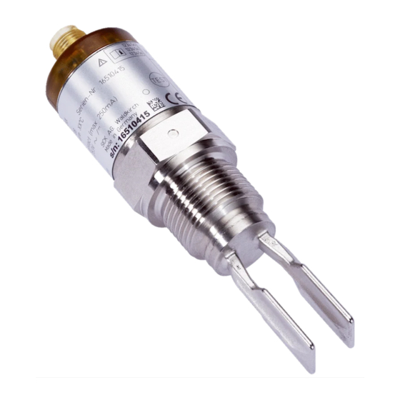
    O P E R A T I N G I N S T R U C T I O N S LFV200 Tun in g Fork...
  • Seite 2: Inhaltsverzeichnis

    Bestimmungsgemäße Verwendung Warnung vor Fehlgebrauch Allgemeine Sicherheitshinweise CE-Konformität Produktbeschreibung Aufbau Arbeitsweise Lagerung und Transport Montieren Allgemeine Hinweise Montagehinweise An die Spannungsversorgung anschließen Anschluss vorbereiten Anschlussplan In Betrieb nehmen Schaltzustandsanzeige Funktionstest Funktionstabelle Instandhalten Wartung Ausbauen Ausbauschritte Entsorgen Anhang Technische Daten LFV200 •...
  • Seite 3: Zu Ihrer Sicherheit

    Sämtliche in dieser Betriebsanleitung beschriebe- 1.5 CE-Konformität nen Handhabungen dürfen nur durch ausgebilde- tes und vom Anlagenbetreiber autorisiertes Fach- Der LFV200 ist CE-konform zum EMVG (89/336/ personal durchgeführt werden. EWG), erfüllt die NAMUR-Empfehlung NE 21 und NE 23 und ist CE-konform zur NSR (73/23/EG).
  • Seite 4: Lagerung Und Transport

    über spezialisierte Recyclingbe- triebe. 3 Montieren 3.1 Allgemeine Hinweise Schaltpunkt Grundsätzlich kann der LFV200 in jeder beliebigen Lage eingebaut werden. Das Gerät muss lediglich so montiert werden, dass sich die Schwinggabel auf Höhe des gewünschten Schaltpunktes befin- det. Abb. 3: Maßnahmen gegen das Eindringen von Feuchtigkeit...
  • Seite 5: Montagehinweise

    An die Spannungsversorgung anschließen Handhabung Strömungen Halten Sie den LFV200 nicht an der Schwinggabel. Damit die Schwinggabel des LFV200 bei Füll- Ein Verbiegen des Schwingelementes führt zur gutbewegungen möglichst wenig Widerstand bie- Zerstörung des Gerätes. tet, sollten die Flächen der Schwinggabel parallel zur Füllgutbewegung stehen.
  • Seite 6 4,5 … 7 mm, Schutzart IP 65. Die M12 x 1-Steckverbindung benötigt ein fertig konfektioniertes Kabel mit Stecker. Abb. 6: Anschlussplan, Transistorausgang bei Ventilstecker DIN 43650 Maximalstanderfassung Minimalstanderfassung Potenzialausgleich Lastwiderstand (Schütz, Relais etc. oder externer Widerstand 100 kΩ) LFV200 •...
  • Seite 7: In Betrieb Nehmen

    Transistor Betriebsart sperrt max. oder 5.2 Funktionstest Schalter offen Der LFV200 hat einen integrierten Testschalter, der Transistor leitet Betriebsart min. Grün magnetisch aktiviert werden kann. Um das Gerät oder zu testen, gehen Sie folgendermaßen vor: Schalter ge- schlossen à...
  • Seite 8: Instandhalten

    Instandhalten 6 Instandhalten 6.1 Wartung Der LFV200 bedarf bei bestimmungsgemäßer Verwendung keiner besonderen Wartung. 7 Ausbauen 7.1 Ausbauschritte Warnung: Achten Sie vor dem Ausbauen auf gefähr- liche Prozessbedingungen wie z. B. Druck im Behälter, hohe Temperaturen, aggres- sive oder toxische Füllgüter etc.
  • Seite 9: Anhang

    Grün Ausgang leitet / Schalter geschlossen Ausgang sperrt / Schalter offen Rot (blinkt) Störung, Ausgang sperrt / Schalter offen Ausgangsgröße Transistorausgang Laststrom max. 250 mA Spannungsabfall max. 1 V Schaltspannung max. 55 V DC Sperrstrom < 10 µA LFV200 •...
  • Seite 10 1,5 mm² Kabelaußendurchmesser 4,5 … 7 mm Elektrische Schutzmaßnahmen Schutzart Ventilstecker DIN 43650 IP 65 M12 x 1-Steckverbindung IP 66/IP 67 (nur bei Ausführung mit Transistorausgang) Überspannungskategorie Schutzklasse - Transistor- ausgang Schutzklasse - kontaktloser Schalter Zulassungen Überfüllsicherung nach WHG LFV200 •...
  • Seite 11 Abb. 9: M12 x 1-Steckverbindung (nur bei Ausführung mit Transistorausgang) 36 mm ø 31,7 mm SW 32 G1 A ø 21,3 mm Abb. 10: DIN 43650-Steckverbindung 8.3 Warenzeichen Alle verwendeten Marken sowie Handels- und Firmennamen sind Eigentum ihrer rechtmäßigen Eigentümer/Urheber. LFV200 •...
  • Seite 12: Operating Instructions

    Storage and transport Mounting General instructions Mounting instructions Connecting to power supply Preparing the connection Wiring plan Set up Indication of the switching status Function test Functional chart Maintain Maintenance Dismounting Dismounting steps Disposal Supplement Technical data Dimensions Trademark LFV200...
  • Seite 13: For Your Safety

    Area of application specic installation standards as well as all prevai- LFV200 is a point level sensor with tuning fork for ling safety regulations and accident prevention rules. level detection. The instrument must only be operated in a It is designed for industrial use in all areas of technically awless and reliable condition.
  • Seite 14: Storage And Transport

    3.1 General instructions Moisture Switching point In general, LFV200 can be installed in any position. The instrument simply has be mounted in such a way that the tuning fork is at the height of the desired switching point.
  • Seite 15: Mounting Instructions

    Connecting to power supply Handling 4 Connecting to power supply Do not hold LFV200 on the tuning fork. Bending the vibrating element will destroy the instrument. 4.1 Preparing the connection Note safety instructions 3.2 Mounting instructions Always keep in mind the following safety instru-...
  • Seite 16: Set Up

    Cable diameter 4.5 … 7 mm, protection IP 65. The M12 x 1 plug connection requires a complete 5.2 Function test confectioned cable with plug. LFV200 has an integrated test switch which can be activated magnetically. Proceed as follows to test the instrument: à...
  • Seite 17: Functional Chart

    5.3 Functional chart 6 Maintain The following chart provides an overview of the 6.1 Maintenance switching conditions depending on the adjusted mode and level. When used as directed in normal condition, LFV200 is maintenance-free. Level Switching sta- Control lamp transistor con- 7 Dismounting Mode max.
  • Seite 18: Supplement

    Output blocks / Switch open Red (ashing) Failure, output blocks / Switch open Output variable Transistor output Load current max. 250 mA Voltage loss max. 1 V Turn-on voltage max. 55 V DC Blocking current < 10 µA Contactless electronic switch LFV200...
  • Seite 19: Dimensions

    Valve plug DIN 43650 IP 65 M12 x 1 plug connection IP 66/IP 67 (only for version with tran- sistor output) Overvoltage category Protection class - Transistor output Protection class - Contactless electronic switch Approvals Overll protection according to WHG LFV200...
  • Seite 20: Trademark

    Fig. 19: M12 x 1 plug connection (only for version with transistor output) 36 mm ø 31,7 mm SW 32 G1 A ø 21,3 mm Fig. 20: DIN 43650 plug connection 8.3 Trademark All brands used as well as trade and company names are property of their lawful proprietor/ originator. LFV200...
  • Seite 21: Manuel De Mise En Service

    Remarques générales Consignes de montage Raccordement à la tension d'alimentation Préparation du raccordement Schéma de raccordement Mettre en service Affichage de l'état de commutation Test de fonctionnement Tableau de fonctionnement Entretien Maintenance Démontage Etapes de démontage Recyclage Annexe Caractéristiques techniques LFV200...
  • Seite 22: Procédé De Fonctionnement

    Emission NE 61326 : 1997 (classe B) Immission EN 61326 : 1997/A1 : 1998 1.2 Définition de l'application DBT : NE 61010-1 : 2001 Le LFV200 est un appareil destiné à la détection de niveau. 2 Description du produit Vous trouverez des informations plus détaillées concernant le domaine d'application du LFV200 au 2.1 Présentation...
  • Seite 23: Stockage Et Transport

    Humidité 3 Montage 3.1 Remarques générales Point de commutation En principe, vous pouvez installer le LFV200 dans n'importe quelle position. Il faudra seulement veiller à ce que les lames vibrantes soient à la hauteur du point de commutation désiré. Fig. 23: Mesures prises contre l'inltration d'humidité...
  • Seite 24: Raccordement À La Tension

    Raccordement à la tension d'alimentation Maniement Ecoulements Ne tenez pas le LFV200 par les lames vibrantes. Une Pour que les lames vibrantes du LFV200 offrent le déformation des lames vibrantes par torsion détruira moins de résistance possible en présence de l'appareil.
  • Seite 25 che mâle. Fig. 26: Schéma de raccordement, sortie transistor pour connecteur type électrovanne DIN 43650 Détection du niveau maximum Détection du niveau minimum Compensation de potentiel Résistance de charge (contacteurs, relais etc. ou résistance externe 100 kΩ) LFV200...
  • Seite 26: Mettre En Service

    Rouge qué tionnement ma- 5.2 Test de fonctionnement Contact de sor- tie ouvert Le détecteur LFV200 possède un commutateur de Transistor com- test intégré qui peut être activé magnétiquement. Mode de fonc- Vert mute Pour pouvoir tester l'appareil, procédez comme suit:...
  • Seite 27: Entretien

    Entretien 6 Entretien 6.1 Maintenance A condition d'une utilisation conforme à son aptitude, l'appareil LFV200 ne nécessite aucun entretien particulier. 7 Démontage 7.1 Etapes de démontage Attention ! Avant de démonter l'appareil, prenez garde aux conditions de process dangereuses comme p. ex. pression dans la cuve, hautes températures, produits agressifs ou toxiques...
  • Seite 28: Annexe

    Défaut, sortie transistor bloquée / sortie électronique statique ouverte Grandeur de sortie Sortie transistor Courant de charge maxi. 250 mA Chute de tension maxi. 1 V Tension de commutation maxi. 55 V DC Courant de blocage < 10 µA LFV200...
  • Seite 29 DIN 43650 Connecteur M12 x 1 (uni- IP 66/IP 67 quement pour la version avec sortie transistor) Catégorie de surtensions Classe de protection - sortie transistor Classe de protection - sortie électronique statique Agréments Sécurité antidébordement selon WHG LFV200...
  • Seite 30 ø 31,7 mm SW 32 G1 A ø 21,3 mm Fig. 30: Connecteur mâle-femelle DIN 43650 8.3 Marque déposée Toutes les marques utilisées ainsi que les noms commerciaux et de sociétés sont la propriété de leurs propriétaires /auteurs légitimes LFV200...
  • Seite 31: Instrucción De Servicio

    Almacenaje y transporte Montaje Indicaciones generales Instrucciones de montaje Conectar a la alimentación de tensión Preparación de la conexión Esquema de conexión Configurar Indicación estado de conexión Prueba de funcionamiento Tabla de funciones Conservar Mantenimiento Desmontaje Secuencia de desmontaje Eliminación Anexo LFV200...
  • Seite 32: Instrucción De Servicio

    La conformidad ha sido valorada según las normas: prescripciones CEM: Emisión EN 61326: 1997 (Clase B) El LFV200 es un sensor para la detección de nivel. Inmisión EN 61326: 1997/A1: 1998 Informaciones detalladas sobre el campo de apli- DBT: EN 61010-1: 2001 cación del LFV200 se encuentran en el capítulo...
  • Seite 33: Almacenaje Y Transporte

    3.1 Indicaciones generales los criterios siguientes: Punto de conmutación Corrosión o deterioro fuerte de la horquilla Básicamente el LFV200 se puede montar en vibratoria cualquier posición. Solamente hay que montar el Falta de vibraciones equipo de forma tal que la horquilla vibratoria se Rotura de la línea hacia el piezoaccionamiento...
  • Seite 34: Conectar A La Alimentación De Tensión

    La posición de la horquilla vibratoria se encuentra señalada por una marca en el hexágono del LFV200. Con ello puede controlarse la posición de la horquilla vibratoria durante el atornillado.
  • Seite 35 El enchufe M12 x 1 requiere de un cable con enchufe confeccionado completamente. Fig. 36: Esquema de conexión, salida de transistor para enchufe de válvula DIN 43650 Detección de nivel máximo Detección de nivel mínimo Conexión equipotencial Resistencia de carga (Protección, Relé etc. o resistencia externa 100 kΩ) LFV200...
  • Seite 36: Configurar

    Modo de opera- rojo quea ción máx. 5.2 Prueba de funcionamiento Interruptor abierto El sensor LFV200 tiene un conmutador de prueba Transistor con- integrado que puede activarse magnéticamente. Modo de opera- verde duce Proceder de la forma siguiente para la comproba- ción min.
  • Seite 37: Conservar

    Conservar 6 Conservar 6.1 Mantenimiento En caso de empleo acorde con las prescripciones el LFV200 no requiere mantenimiento especial alguno. 7 Desmontaje 7.1 Secuencia de desmontaje Advertencia: Antes del desmontaje, prestar atención a condiciones de proceso peligrosas tales como p. Ej., presión en el depósito, altas temperaturas, productos agresivos o tóxicos,...
  • Seite 38: Anexo

    Interrupción, salida bloquea / interruptor abierto Magnitud de salida Salida del transistor Corriente bajo carga max. 250 mA Caída de tensión max. 1 V Tensión de activación max. 55 V DC Corriente en estado de no < 10 µA conducción LFV200...
  • Seite 39 M12 x 1 (solo para la versión con salida de tran- sistor) Categoría de sobretensión Tipo de protección - Salida de transistor Clase de protección - inter- ruptor sin contacto Homologaciones Seguro contra sobrecarga según la ley del régimen hidráulico (WHG) LFV200...
  • Seite 40: Marca Registrada

    36 mm ø 31,7 mm SW 32 G1 A ø 21,3 mm Fig. 40: DIN 43650-Acoplamiento de enchufe 8.3 Marca registrada Todas las marcas y nombres comerciales o em- presariales empleados pertenecen al propietario/ autor legal. LFV200...
  • Seite 41 Anexo LFV200...
  • Seite 42 Anexo LFV200...
  • Seite 43 Anexo LFV200...
  • Seite 44 E-Mail support@sick.jp Nederlands Phone +31 (0)30 229 25 44 E-Mail info@sick.nl Norge More representatives and Phone +47 67 81 50 00 agencies in all major industrial nations at www.sick.com E-Mail auste ord@sick.no SICK AG | Waldkirch | Germany | www.sick.com 34960-01-080423...

Inhaltsverzeichnis