Hitachi AF-RTU-01 Installations- Und Betriebshandbuch
Inhaltsverzeichnis
Verfügbare Sprachen
Verfügbare Sprachen
Quicklinks
INSTALLATION AND OPERATION MANUAL
MANUAL DE INSTALACIÓN Y FUNCIONAMIENTO
INSTALLATIONS- UND BETRIEBSHANDBUCH
MANUEL D'INSTALLATION
MANUALE D'INSTALLAZIONE E D'USO
MANUAL DE INSTALAÇÃO E DE FUNCIONAMENTO
BRUGER- OG MONTERINGSVEJLEDNING
INSTALLATIE- EN BEDIENINGSHANDLEIDING
INSTALLATIONS- OCH ANVÄNDARHANDBOK
ΕΓΧΕΙΡΙΔΙΟ ΕΓΚΑΤΑΣΤΑΣΗΣ ΚΑΙ ΛΕΙΤΟΥΡΓΙΑΣ
Do not perform installation work without referring to our installation manual.
No realice trabajos de instalación sin consultar el manual de instalación.
Führen Sie die Installationsarbeiten gemäß dem Installationshandbuch durch.
Consulter notre manuel avant de réaliser une quelconque installation.
Gli interventi d'installazione devono essere eseguiti attenendosi alle istruzioni contenute in questo manuale.
Não execute trabalhos de instalação sem antes consultar o nosso manual de instalação.
Udfør ikke monteringsarbejde uden først at læse monteringsvejledningen.
Begin niet met de installatie voordat u de installatiehandleiding hebt doorgelezen.
Utför inte något installationsarbete utan att först läsa installationshandboken.
Μην εκτελείτε εργασίες εγκατάστασης χωρίς να ανατρέξετε στο εγχειρίδιο εγκατάστασης.
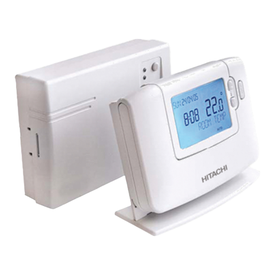
Wireless Programmable Room thermostat
Termostato de ambiente inalámbrico y programable
Kabelloser, programmierbarer Raumthermostat
Thermostat d'ambiance sans fil programmable
Termostato ambientale senza fili programmabile
Termostato programável sem fios de espaço interior
Trådløs programmerbar rumtermostat
Draadloze programmeerbare kamerthermostaat
Programmerbar trådlös rumstermostat
Ασύρματος προγραμματιζόμενος θερμοστάτης δωματίου
50023397-008
Kapitel
Inhaltsverzeichnis
Fehlerbehebung

Verwandte Anleitungen für Hitachi AF-RTU-01


Inhaltszusammenfassung für Hitachi AF-RTU-01
- Seite 1 Wireless Programmable Room thermostat Termostato de ambiente inalámbrico y programable Kabelloser, programmierbarer Raumthermostat Thermostat d’ambiance sans fil programmable Termostato ambientale senza fili programmabile Termostato programável sem fios de espaço interior Trådløs programmerbar rumtermostat Draadloze programmeerbare kamerthermostaat Programmerbar trådlös rumstermostat Ασύρματος προγραμματιζόμενος θερμοστάτης δωματίου INSTALLATION AND OPERATION MANUAL MANUAL DE INSTALACIÓN Y FUNCIONAMIENTO INSTALLATIONS- UND BETRIEBSHANDBUCH...
-
Seite 24: Beschreibung
Installations- und Betriebshandbuch Installations- und Betriebshandbuch Beschreibung Innenraumgerät kommuniziert Funkempfänger auf der Funkfrequenz 868MHz (RF), um das AquaFREEsystem zu steuern. Keines der Produkte kommuniziert mit anderen RF-Produkten, die andere Frequenzen oder Kommunikationsprotokolle verwenden. Hinweis: Der RF-Link zwischen dem Innenraumgerät und dem Funkempfänger in System-Packs ist werkseitig konfiguriert und daher SOLLTEN diese Komponenten am selben Ort installiert werden. -
Seite 25: Installationsinformationen
Installations- und Betriebshandbuch 1. Installationsinformationen Da diese Produkte zur Kommunikation die RF-Technologie nutzen, muss die Installation mit besonderer Sorgfalt durchgeführt werden. Sowohl der Standort der RF-Komponenten als auch die Bauart des Gebäudes können die Leistung des RF-Systems beeinflussen. Um die Zuverlässigkeit des Systems zu gewährleisten, lesen Sie die nachstehenden Informationen sorgsam durch und halten Sie sich daran. -
Seite 26: Installation Des Programmierbaren Thermostats
Installations- und Betriebshandbuch 2. Installation des programmierbaren Thermostats Folgen Sie den nachstehenden Abbildungen und Informationen in der angegebenen Reihenfolge, um den Funkempfänger und das Raumgerät richtig zu installieren Im Abschnitt 3. „Installationsmodus“ auf Seite 7 finden Sie Informationen über die Aktivierung der Sonderfunktionen und über andere verfügbare Systemoptionen. 2.1 Installieren des Funkempfängers Der Empfängerkasten ist ein RF-Gerät. -
Seite 27: Installieren Des Innenraumgeräts
Installations- und Betriebshandbuch 2.2 Installieren des Innenraumgeräts 2.2.1 Einschalten Einbau der Batterien: a. Heben Sie die Frontabdeckung des Innenraumgeräts an. Dort finden Sie den Batteriedeckel und die Bedienelemente des Geräts. b. Nehmen Sie den Batteriedeckel ab, indem Sie draufdrücken und ihn hinausschieben. c. -
Seite 28: Standortwahl Des Innenraumgeräts
Installations- und Betriebshandbuch 2.2.3 Standortwahl des Innenraumgeräts Suchen Sie während sich das Gerät gemäß Abschnitt 2.2.2 noch im Testmodus befindet einen Standort für das Innenraumgerät und berücksichtigen Sie dabei die folgenden Abbildungen und Informationen: 1. Wählen Sie einen geeigneten Standort aus, an dem das Übertragungssignal gut empfangen wird. Die Übertragung ist stabil, wenn die grüne LED des Funkempfängers alle 5 Sekunden blinkt. -
Seite 29: Installationsmodus
Installations- und Betriebshandbuch 3. Installationsmodus Im Installationsmodus können Systemeinstellungen für bestimmte Anwendungen geändert werden, um die Sonderfunktionen des Innenraumgeräts auf andere Weise zu nutzen oder die werkseitigen Einstellungen der Parameter zu ändern. Die Parameter sind in zwei Gruppen aufgegliedert: - Parameter der Kategorie 1 - Innenraumgeräteeinstellungen - Parameter der Kategorie 2 - Systemeinrichtung Sie sind alle im Abschnitt 3.5 Installationsparametertabelle aufgeführt. -
Seite 30: Verwenden Des Innenraumgeräts Für Spezielle Anwendungen
Installations- und Betriebshandbuch 3.3 Verwenden des Innenraumgeräts für spezielle Anwendungen Das Innenraumgerät ist ein vielseitiges Steuergerät, mit dem viele verschiedene Anwendungen gesteuert werden können. Einige Systemparameter im Menü des Innenraumgeräts finden keine Anwendung. Bitte beachten Sie auch andere Änderungen bei der Einstellung der Optimierung und des Proportionalbands gemäß... -
Seite 31: Installationsparametertabelle
Installations- und Betriebshandbuch 3.5 Installationsparametertabelle 3.5.1 Kategorie 1 - Innenraumgeräteeinstellungen Parameter Parameter Standardmäßige Optionale Einstellungen Werkseinstellung Kategorie 1 Parameter - Innenraumgeräteeinstellungen Anzeige Beschreibung Anzeige Beschreibung AM-PM / 24-Std.- 1:CL 24-Std- 12-Std. – AM/PM- Anzeige Zeitanzeigeformat Uhrzeitanzeigeformat Reset-Zeit / Temp.- 2:rP Zeit- / Temp.- Zeit / Temperatur Programm... -
Seite 32: Kategorie 2 - Systemeinstellungen
Installations- und Betriebshandbuch 3.5.2 Kategorie 2 - Systemeinstellungen HINWEIS: Um einen korrekten Wärmepumpensystembetrieb zu gewährleisten, muss Parameter 8:Su richtig eingestellt sein. Siehe Hinweis im Abschnitt 3,3 „Verwendung des Innenraumgeräts für spezielle Anwendungen“. Parameter Parameter Standardmäßige Optionale Einstellungen Werkseinstellung Parameter der Kategorie 2 – Systemeinrichtung (Taste drücken, um Zugang zu dieser Kategorie zu erhalten). -
Seite 33: Teach-In-/ Re-Teach-In-Verfahren
Installations- und Betriebshandbuch 4. Teach-in-/ Re-Teach-in-Verfahren Das unten beshriebene Teach-in-Verfahren ist erforderlich, wenn: • eine der Systemkomponenten (Innenraumgerät oder Funkempfänger) ersetzt werden. • Im Funkempfänger sind falsche oder keine Teach-in-Daten gespeichert (z.B. wenn voreingebundene System-Pack-Komponenten fehlangepasst sind). HINWEIS: Während des Teach-in-Verfahrens mindestens ca. 1 m Abstand zwischen dem Innenraumgerät und dem Funkempfänger halten. -
Seite 34: Fehlersuche
Installations- und Betriebshandbuch 5. Fehlersuche 5.1 Leitfaden zur Fehlersuche Symptom (Störungsnachricht) Mögliche Ursache Abhilfemaßnahme Der Innenraumthermostat zeigt Das ist normal. Der Empfängerkasten Mithilfe der Taste kann der das Symbol an, doch das schaltet das Relais entsprechend dem Temperatursollwert um ein paar Relais des Empfängerkastens Anforderungssignal (0-100%) vom Grad verändert werden. - Seite 112 50023397-008...