Omnimount POWER 55 Benutzerhandbuch
Motorized wall mounting system
Quicklinks
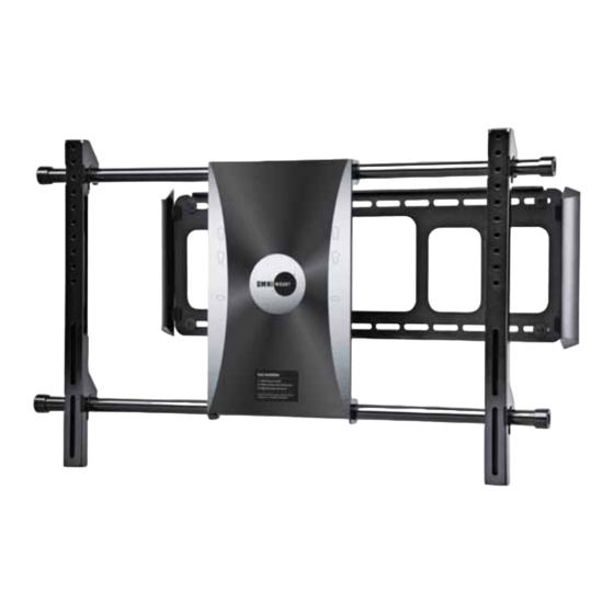
POWER 55
Motorized Wall Mounting System
Instruction Manual
EN
Manual De Instrucciones
ES
FR
Manuel D'instructions
DE
Benutzerhandbuch
NL
Instructiehandleiding
IT
Manuale Di Istruzioni
RU
Руководство По Эксплуатации
EN
Images may differ from actual product
ES
El producto real puede variar respecto a la imagen mostrada.
FR
Le produit réel peut différer de l'illustration.
DE
Abbildung weicht möglicherweise von tatsächlichem Produkt
NL
De afbeelding kan verschillend zijn van het eigenlijke product.
IT
L'immagine può non corrispondere al prodotto effettivo.
RU
Изображение
товара, представленное в этом документе, может отличаться от реального внешнего вида товара
UL10378
ULN #
POWER 55 = L7-UL10378-CON-041609vA
PN #
Maximum screen size: 55"
Maximum weight 110 lbs – 50 KG
CAUTION: DO NOT EXCEED MAXIMUM LISTED
WEIGHT CAPACITY. SERIOUS INJURY OR PROPERTY
DAMAGE MAY OCCUR!
VERSION
A
.

Verwandte Anleitungen für Omnimount POWER 55


Inhaltszusammenfassung für Omnimount POWER 55
- Seite 1 POWER 55 UL10378 ULN # POWER 55 = L7-UL10378-CON-041609vA PN # Motorized Wall Mounting System VERSION Instruction Manual Manual De Instrucciones Manuel D’instructions Maximum screen size: 55” Benutzerhandbuch Maximum weight 110 lbs – 50 KG Instructiehandleiding CAUTION: DO NOT EXCEED MAXIMUM LISTED Manuale Di Istruzioni WEIGHT CAPACITY.
- Seite 2 OmniMount customer service at 800.668.6848 or info@omnimount.com. Do not install or assemble if the product or hardware is damaged or missing. If you require replacement parts, contact OmniMount Customer Service at 800.668.6848 or Info@omnimount.com. International customers need to contact a local distributor for assistance.
- Seite 3 Installeer of monteer het product niet als het product of de bevestigingsmiddelen beschadigd zijn of ontbreken. Als u vervangingsonderdelen nodig heeft, kunt u contact opnemen met de OmniMount-klantendienst op het nummer 800.668.6848 of via e-mail op info@omnimount.com. Internationale klanten dienen contact op te nemen met een plaatselijke leverancier.
- Seite 4 TABLE OF CONTENTS Maximum Weight Hardware List P6-7 Symbol Key Wood Stud Wall Installation P9-13 Solid Concrete Wall Installation P14-17 Slim TV Installation P18-19 Non-VESA Monitor Installation P20-24 VESA Monitor Installation P25-30 IR Receiver P31-32 Power Cable Management Remote Control Functions P35-41 Trouble Shooting P42-43...
- Seite 5 WEIGHT CAPACITY MAXIMUM WEIGHT CAPACITY POUNDS (LBS) / KILOGRAMS (KG) MAXIMUM SCREEN SIZE MÁXIMA CAPACIDAD DE PESO LIBRAS (LB) / KILOGRAMOS (KG) TAMAÑO DE PANTALLA MÁXIMO CAPACITE DE CHARGE MAXIMALE LIVRES (LB) / KILOGRAMMERS (KG) TAILLE D’ÉCRAN MAXIMALE PFUND (lbs) MAXIMALE BILDSCHIRMGRÖSSE MAXIMALE BELASTBARKEIT AM.
- Seite 6 CONTENTS Contents - POWER 55 Pouch # Part # Description Wall Mount Wall Template Instruction Manual Vertical Rails Horizontal Rails (485mm End Cap to End Cap) End Caps & Screws Power Adapter Remote Control IR Receiver Mylar Sticker Tension Screws (Pre Installed) M6 x 7mm...
- Seite 7 CONTENTS CONTENTS Monitor Kit - POWER 55 Pouch # Part # Description Philips screws M4 x 15mm Philips screws M4 x 45mm Philips screws M5 x 15mm Philips screws M5 x 45mm Philips screws M6 x 15mm Philips screws M6 X 20mm...
- Seite 8 SYMBOL KEY Drill Level Caution Hammer Optional Agujerear Nivel Precaución Martillo Opcional Percer Niveau Attention Marteau Optionnel Bohren Wasserwaage Vorsicht Hammer Optional Boor Waterpas Voorzichtig Hamer Optioneel Forare Livellare Attenzione Martello Opzionale Сверление Уровень Предостережение Молоток Дополнительно Pencil Mark Phillips Screwdriver Allen Wrench Tools Needed Marque con lápiz...
-
Seite 9: Wood Stud Installation
WOOD STUD INSTALLATION Find stud(s) and mark edge and center locations. Ubique el panel y marque las ubicaciones de los bordes y el centro. Repérez l'emplacement d'une poutre, puis marquez l'emplacement des bords et du centre de cette poutre. Suchen Sie den Balken und markieren Sie Ränder und Mitte. Zoek de drager en markeer de rand- en middenlocaties. - Seite 10 WOOD STUD INSTALLATION Use wall plate or wall template to mark mounting locations Use la guía o placa de la pared para marcar el lugar donde se realizará la instalación Utilisez la plaque ou le gabarit mural pour marquer les emplacements de montage Verwenden Sie die Wandplatte oder die Wandschablone, um die Montagestellen zu markieren Wandplaat of wandsjabloon gebruiken om de montageplaatsen af te tekenen Utilizzare la piastra a muro o la guida per segnare le posizioni di montaggio...
- Seite 11 WOOD STUD INSTALLATION CAUTION: Any Wood Stud Installation Greater than 16” Wide Must use a Dry Wall Anchor (Not Included) in the (B-Left) Section of the Wall Template. ADVERTENCIA: Toda instalación con paneles de madera, cuyo ancho sea superior a 40,64 cm (16 pulgadas) debe llevar un taco de pared (no incluido) en la sección (B izquierda) de la plantilla de pared.
- Seite 12 WOOD STUD INSTALLATION Wood Pilot Pilot Hole Size Pilot Drill Depth 1/8” inch 2” inch 4 mm 55 mm Wood Stud Wall Installation Drill pilot hole Instalación en pared con paneles de madera Realice el agujero piloto Installation murale sur poteau de cloison en bois Percez le trou de guidage Montage an Holzbalken an der Wand Bohren Sie die Vorbohrung...
- Seite 13 WOOD STUD INSTALLATION Tighten Fastener Ajuste el sujetador Serrez l'attache Ziehen Sie die Befestigung fest Draai de bevestiging vast Serrare il dispositivo di fissaggio Затяните крепление Hand tools only Herramientas de mano solamente Outils manuels uniquement Nur Handwerkzeuge Gebruik alleen handgereedschap Serrare esclusivamente a mano Используйте...
- Seite 14 CONCRETE INSTALLATION Solid Concrete Only Do Not Drill Into Mortar Use wall plate or wall template to mark mounting locations Use la guía o placa de la pared para marcar el lugar donde se realizará la instalación Utilisez la plaque ou le gabarit mural pour marquer les emplacements de montage Verwenden Sie die Wandplatte oder die Wandschablone, um die Montagestellen zu markieren Wandplaat of wandsjabloon gebruiken om de montageplaatsen af te tekenen Utilizzare la piastra a muro o la guida per segnare le posizioni di montaggio...
- Seite 15 CONCRETE INSTALLATION Place Wall Template (2) on solid concrete wall. A total of 6 Wall Anchors (W-B) and 6 Wall Screws (W-A) must be installed. Refer to Wall Template (2) for further instructions. Coloque la plantilla (2) sobre una pared de hormigón. Deben colocarse 6 tacos de pared (W-B) y 6 tornillos (W-A) en total. Para obtener más instrucciones, consulte la plantilla de pared (2).
- Seite 16 CONCRETE INSTALLATION Concrete Pilot Pilot Hole Size Pilot Drill Depth 5/16” inch 2 1/8” inch 8 mm 55 mm Not Included Concrete Wall Installation Drill pilot hole Solid Concrete Instalación en pared de hormigón Realice el agujero guía Concreto sólido Installation sur mur en béton Percez le trou de guidage Béton massif...
- Seite 17 CONCRETE INSTALLATION For solid concrete wall installation 6 screws and anchors are required. Para instalar el soporte sobre una pared de hormigón, se necesitan 6 tornillos y tacos. Pour une installation sur mur plein en béton, 6 vis et brides sont nécessaires. Für die Montage an einer Betonmauer werden 6 Schrauben und Dübel benötigt.
- Seite 18 READ!!! SLIM TV (6 cm thickness or less only) Mount comes adjusted factory default suitable to fit most TV’s. This step is ONLY Slim Size Televisions with a depth of 2.4 in. (6 cm) or less. Check you TV installation Manual if your TV fits this criteria. You must adjust TV’s in this size range in order for the mount to function properly.
- Seite 19 READ!!! SLIM TV (6 cm thickness or less only) SPRING TENSION IS HIGH. DO NOT LOOSE GRIP ON SCREWDRIVER / ROD! Once second screw is removed, slowly allow the tension spring to unwind upwards. Allow it uncoil until it rests. If in future a larger Monitor / TV are to be installed on Auto Wall Mount, Please Reverse Steps Above to adjust Tension to Springs.
- Seite 20 NON-VESA / LARGER MONITOR INSTALLATION CAUTION! - SCREWS BOTTOMING OUT M-A – Extra Steel Washers (Not Included) Attention: If screw "bottoms out" use steel washers (not included) to take up slack Atención: Si el tornillo hace tope, utilice arandelas (no se incluyen) para ajustarlo al máximo. Attention : Si les vis dépassent en dessous, utilisez des rondelles (non incluses) pour compenser Achtung: Falls sich die Schraube „eingräbt“, verwenden Sie Unterlegscheiben (nicht im Lieferumfang enthalten), um die Schraubenkraft auf eine größere Fläche zu verteilen...
- Seite 21 NON-VESA / LARGER MONITOR INSTALLATION SPACERS - OPTIONS M-A – Extra Steel Washers (Not Included) Use spacers for recessed mounting holes or to access A/V inputs Use los espaciadores para agujeros de montaje empotrados o para acceder a las entradas de A/V Utilisez les entretoises sur les trous de montage encastrés ou pour accéder aux entrées A/V Verwenden Sie Abstandhalter für zurückversetzte Montagebohrungen oder um A/V-Eingänge zu erreichen Gebruik afstandshouders voor verzonken montageopeningen of voor toegang tot A/V-ingangen...
- Seite 22 NON-VESA / LARGER MONITOR INSTALLATION M-A – Attach monitor using monitor hardware, M-A, M-B, etc… Coloque la pantalla utilizando los materiales de instalación de la pantalla, M-A, M-B, etc… Installer le moniteur avec les fixations de moniteur, M-A, M-B, etc… Bringen Sie den Bildschirm mit den Bildschirm-Befestigungsteilen M-A, M-B usw.
- Seite 23 NON-VESA / LARGER MONITOR INSTALLATION Attach covers Coloque las cubiertas Fixez les caches Befestigen Sie die Abdeckungen Bevestig de bedekkingen Montare i coperchi Установите крышки Install Instale Installer Anbringen Installeer Installare Установить...
- Seite 24 NON-VESA / LARGER MONITOR INSTALLATION This step may require two people Este paso podría requerir de dos personas. Il est possible que deux personnes soient nécessaires pour cette étape Für diesen Schritt sind eventuell zwei Personen erforderlich Hiervoor zijn mogelijk twee mensen nodig Per questa operazione possono essere necessarie due persone Для...
- Seite 25 VESA MONITOR INSTALLATION 200mm 100mm 200mm 100mm 200mm VESA 200mm x 200mm 100mm x 200 mm...
- Seite 26 VESA MONITOR INSTALLATION Punch out perforated lines to access horizontal rail screws (12). Troquele las líneas perforadas para acceder a los tornillos del raíl horizontal (12). Découpez les lignes perforées pour accéder aux vis (12) du rail horizontal. Stanzen Sie die perforierten Linien aus, um Zugriff auf die Schrauben der horizontalen Schienen (12) zu erhalten. Druk de geperforeerde lijnen in om bij de schroeven (12) van de horizontale stang te komen.
- Seite 27 VESA MONITOR INSTALLATION Loosen Fastener Remove Afloje el sujetador Retire Desserrez l'attache Retirez Lösen Sie die Befestigung Entfernen Sie Draai de bevestiging los Verwijder Allentare il dispositivo di fissaggio Rimuovere Ослабьте крепление Удалите Remove the End Caps (6) from Horizontal Rails (5). The End Cap Sticker must be peeled back to access the screws. Discard End Cap Stickers.
- Seite 28 VESA MONITOR INSTALLATION Remove Retire Retirez Entfernen Sie Verwijder Rimuovere Удалите Remove Retire Retirez Entfernen Sie Verwijder Rimuovere Удалите...
- Seite 29 VESA MONITOR INSTALLATION M-A ~ M-J Partially install top two Philips screws (M-A ~ M-J). Please use Washers (M-K) for screw sizes M4 and M5 (M-A ~ MD). Instale parcialmente los dos tornillos Philips superiores (M-A ~ M-J). Utilice arandelas (M-K) para los tornillos M4 y M5 (M-A ~ MD).
- Seite 30 VESA MONITOR INSTALLATION Connect monitor and adapter to mount Conecte el monitor y el adaptador al soporte Connectez le moniteur et l'adaptateur sur le support Befestigen Sie den Bildschirm und den Adapter an der Halterung Sluit de monitor en adapter aan voor de montage Collegare lo schermo e l'adattatore alla...
- Seite 31 IR RECEIVER Remove Retire Retirez Entfernen Sie Verwijder Rimuovere Удалите Figure 1 IMPORTANT NOTE: The IR Receiver Must be placed with the Top of the Head facing forward AVISO IMPORTANTE: El receptor infrarrojo debe colocarse con la parte superior del cabezal hacia adelante.
- Seite 32 IR RECEIVER 20° 12 M (49 ft) 20° IR (Infrared Receiver) Attach the IR receiver making sure nothing will obstruct the transmission from where the TV will be viewed. Cuando instale el receptor IR, cerciórese de que no haya nada entre el televisor y el lugar desde donde éste se verá, que pudiera obstruir la transmisión.
-
Seite 33: Power Cord
POWER CORD WARNING!! DO NOT PLUG IN DC12V (POWER CORD) UNTIL ALL COMMUNICATION CABLES (IR RECIEVER, RS 232 [Not Included] ) ARE PLUGGED IN. ADVERTENCIA NO CONECTE EL DC12V (CABLE DE ALIMENTACIÓN) HASTA QUE TODOS LOS CABLES DE COMUNICACIÓN (RECEPTOR IR, RS 232 [no incluido]) ESTÉN ENCHUFADOS. AVERTISSEMENT !! NE PAS BRANCHER LES FILS ÉLECTRIQUES (12 V CC) AVANT QUE TOUS LES CÂBLES DE COMMUNICATION (RÉCEPTEUR IR, RS 232 [non fourni]) NE SOIENT BRANCHÉS. -
Seite 34: Cable Management
CABLE MANAGEMENT Route Cables Tienda los cables Installez les câbles Verlegen Sie die Kabel Plaats de kabels Inserire i cavi Укладка кабелей Secure Loose Cables with Zip Ties Asegure los cables sueltos con precintos plásticos. Attachez les câbles libres avec des attaches autobloquantes. Sichern Sie lose Kabel mit Kabelbindern Maak losse kabels aan elkaar vast met een kabeldas Fissare i cavi sciolti con fascette fermacavi... - Seite 35 REMOTE CONTROL PROGRAMMING (English) ATTENTION! Must set WALL DETECT RIGHT first. Failure to do this may result in poor performance of Wall Mount. If set LEFT WALL DETECT, please use the SETUP / RESET to clear memory SETUP: Push / Collapse the Wall Mount Flat against the Wall, Press and Hold for 5 seconds to LED LIGHT set the home position (note: this also clears...
- Seite 36 REMOTE CONTROL PROGRAMMING (Español ) ATENCION! Primero, se debe establecer la DETECCIÓN DE PARED a la DERECHA. Cualquier falla que pusiera ocurrir al realizar esto, podría resultar en un escaso rendimiento del Soporte de pared. Si establece la DETECCIÓN DE PARED a la IZQUIERDA, utilice SETUP / RESET (INSTALAR / REINICIAR) para vaciar la memoria.
- Seite 37 REMOTE CONTROL PROGRAMMING (Français) ATTENTION! Vous devez d’abord régler la DÉTECTION DU MUR DROIT. Si vous n’y parvenez pas le support pourrait ne pas fonctionner normalement. Pour régler ensuite la DÉTECTION DU MUR GAUCHE, vous devez d’abord utiliser la fonction SETUP / RESET (RÉGLAGE / RÉINITIALISATION) pour remettre la mémoire à...
- Seite 38 REMOTE CONTROL PROGRAMMING - (DEUTSCH) ACHTUNG! Die WANDERKENNUNG muss zuerst RECHTS eingestellt werden. Das Nichtbeachten dieser Maßnahme führt möglicherweise zu einer schlechten Leistung der Wandhalterung. Bei der Einstellung der LINKEN WANDERKENNUNG stellen Sie sicher, dass Sie die FUNKTION SETUP / WIEDERHERSTELLEN zum Löschen des Speichers verwenden.
- Seite 39 REMOTE CONTROL PROGRAMMING - (NEDERLANDS) OPGEPAST! “WALL DETECT RIGHT” (muur rechts waarnemen) eerst instellen. Als dit niet gedaan wordt, kan dit een slechte prestatie van het wandmontagesysteem tot gevolg hebben. Indien “LEFT WALL DETECT” (muur links waarnemen) is ingesteld, gebruik dan de knop SETUP/RESET om het geheugen te wissen. STAP 1 = SETUP wist het geugen en “Set Home”...
- Seite 40 REMOTE CONTROL PROGRAMMING - (ITALIANO) ATTENZIONE! Impostare prima il RILEVAMENTO PARETE A DESTRA. La non osservanza di questa istruzione può comportare una scarsa prestazione della base di montaggio a parete. Se è stato impostato il RILEVAMENTO PARETE A SINISTRA, utilizzare il tasto SETUP / RESET per cancellare il contenuto della memoria. FASE 1 = SETUP cancella il contenuto della memoria e imposta la posizione iniziale –...
- Seite 41 REMOTE CONTROL PROGRAMMING - (РУССКИЙ) Внимание! Сначала необходимо выполнить ПОДГОНКУ ПО РАССТОЯНИЮ ДО СТЕНЫ СПРАВА Невыполнение данного указания может привести к низким эксплуатационным характеристикам настенного кронштейна. При выполнении ПОДГОНКИ ПО РАССТОЯНИЮ ДО СТЕНЫ СЛЕВА используйте кнопку SETUP / RESET (УСТАНОВКА/СБРОС) для очистки памяти. ШАГ...
- Seite 42 PAGE LEFT BLANK INTENTIONALLY Page Left Blank Intentionally Esta página se dejó en blanco intencionalmente Cette page est intentionnellement vierge Seite absichtlich freigelassen Pagina werd leeg gehouden Pagina lasciata intenzionalmente vuota Пустая страница...
- Seite 43 PAGE LEFT BLANK INTENTIONALLY Page Left Blank Intentionally Esta página se dejó en blanco intencionalmente Cette page est intentionnellement vierge Seite absichtlich freigelassen Pagina werd leeg gehouden Pagina lasciata intenzionalmente vuota Пустая страница...
- Seite 44 PAGE LEFT BLANK INTENTIONALLY Page Left Blank Intentionally Esta página se dejó en blanco intencionalmente Cette page est intentionnellement vierge Seite absichtlich freigelassen Pagina werd leeg gehouden Pagina lasciata intenzionalmente vuota Пустая страница...
- Seite 45 Trouble Shooting – ENGLISH Unit Must be Level. If not level, TV will lean on one side and Operation Speed will be irregular. Longevity of mount use will be greatly reduced from not properly leveling the wall plate. Wood Stud: Wall Mount Must have at least 4 Wall Point Location Mounted. Any Wood Stud Installation Greater than 16”...
- Seite 46 Fehlerbehebung – DEUTSCH Komponente muss ausgerichtet werden. Wenn der Fernseher nicht waagerecht ausgerichtet ist, neigt er zu einer Seite und die Betriebsgeschwindigkeit ist ungleichmäßig. Die Lebensdauer der Halterung wird durch die unangemessene Ausrichtung der Wandplatte entscheidend verkürzt. Holzbalken: Für die Wandhalterung müssen mindestens 4 Wandpunkte festgelegt und vorbereitet werden. Für jede Holzbalkenmontage, die breiter als 40,6 cm ist, muss ein Trockenmauerdübel (nicht im Lieferumfang enthalten) im Halterungsbereich (B-links) verwendet werden –...
- Seite 47 (800.668.6848) o escríbanos a info@omnimount.com. Deberá proporcionar el recibo original. Si fuera necesario enviar el producto a OmniMount para revisarlo, los gastos de envío correrán por su cuenta. El producto de reemplazo que se le envíe se le devolverá con los gastos de envío pagos.
- Seite 48 БЛАГОДАРИМ ВАС ЗА ПРИОБРЕТЕНИЕ ИЗДЕЛИЯ OMNIMOUNT (RU) Russian OmniMount Systems, Inc. 8201 South 48th Street Phoenix, AZ 85044-5355 1-800-MOUNT-IT (1-800-668-6848) www.omnimount.com All trademarks are the property of their respective companies. OmniMount is a registered trademark of OmniMount Systems, Inc. © 2006...