
Verwandte Anleitungen für Grundfos Conex DIS-D


Inhaltszusammenfassung für Grundfos Conex DIS-D
- Seite 1 GRUNDFOS INSTRUCTIONS Conex DIS-D, Conex DIS-PR ® ® Instrument amplifier and controller Installation and operating instructions...
- Seite 3 ® ® Conex DIS-D, Conex DIS-PR English (GB) Installation and operating instructions....... . . 4 Deutsch (DE) Montage- und Betriebsanleitung .
-
Seite 4: Inhaltsverzeichnis
Symbols used in this document practice. General information Applications These complete installation and operating Note instructions are also available on Safety www.grundfos.com. Obligations of owner Avoidance of danger 1. Symbols used in this document Identification Nameplate Warning Type key If these safety instructions are not Technical data observed, it may result in personal injury. -
Seite 5: General Information
Grundfos. We shall be pleased to support you with our The owner is also responsible for ensuring that this... -
Seite 6: Identification
Measuring amplifier and controller DIS-D 1-D, W-G Dosing DIS-D 346-2000-10000 Instrumentation DIS-PR S/N: 08/00207 Standard Conex DIS-D, 230/240V 50/60Hz Input parameter 1 15 VA, IP 65 96622392P1108020800207 Redox (ORP) Chlorine (Cl chlorine dioxide (ClO ) or ozone (O Mounting ®... -
Seite 7: Technical Data
6. Technical data 6.3.2 Instrument amplifier functions Measured-value display: 6.1 Instrument versions measured value in Display mode physical dimension, 6.1.1 Instrument amplifier temperature display: in °C ® (only Conex DIS-PR) Type Measured variables Temperature comp. Manual or automatic with ® Chlorine, chlorine dioxide or (Conex DIS-PR) -
Seite 8: Measuring Ranges
6.4 Measuring ranges Chlorine Cl Chlorine dioxide ClO 0 to 2 mg/l; 0 to 20 mg/l* Ozone O 0 to 14 pH; 2 to 12 pH; 5 to 9 pH 0 to 1000 mV; Redox 0 to 1500 mV Pt100 -5 to +120 °C For O the actual measuring range is limited to 0... -
Seite 9: Installation
7. Installation 1. Drill three holes (8) as shown in the diagram and insert the supplied dowels. 7.1 Transport and storage 2. Screw the screw (A) into the top centre dowel until it projects by approx. 1 cm. See fig. 4. •... -
Seite 10: Commissioning / Electrical Connections
8. Commissioning / electrical connections Warning Switch off the power supply before installing! Enclosure class IP65 is only guaranteed with the front panel of the terminals enclosure closed and with appropriate cable glands or dummy caps. Warning Switch off the power supply before connecting the power supply cable and the relay contacts! For safety reasons, the protective conductor must be connected... -
Seite 11: Terminals
8.1 Terminals Alarm N.C. Relay N.O. M B/R G/C N PE 24 V DC 115/120 V / 230/240 V Conex DIS-D ® ® Fig. 5 Conex DIS-D Alarm N.C. Relay N.O. N PE Pt 100 24 V DC 115/120 V / 230/240 V Conex DIS-PR ®... -
Seite 12: Relay Outputs
8.2 Relay outputs 8.3 Current output The connection of the relay outputs Make sure that the polarity of the current Caution output is correct! Maximum load: 500 Ω. depends on the application as well as the Note device controlled. Therefore the The current output can be set to the two standard connections described below should only ranges, "0 to 20 mA"... -
Seite 13: Connection Of Measuring Cells
8.5 Connection of measuring cells 20 21 22 20 21 22 14 16 14 16 9, 10 Fig. 10 Wiring diagrams for AQC-D12 measuring cells 20 21 22 14 16 Fig. 8 Wiring diagrams for AQC-D1/-D2/-D3 measuring cells Fig. 11 Wiring diagrams for AQC-D13 measuring cells 20 21 22... - Seite 14 23 24 Fig. 12 Wiring diagram for single rod measuring chains for pH/redox Pos. Component Inner conductor Outer conductor...
-
Seite 15: Operation
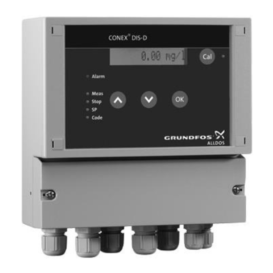
9. Operation 9.1 Control and display elements Fig. 13 Control and display elements LEDs Input buttons Pos. Description Pos. Description Alarm: The alarm LED flashes with fault or [Up]: incorrect input. • Increases values. • Switches between the menus. Meas: The measuring mode LED illuminates when measurement is active. -
Seite 16: Switching The Instrument On/Off
9.2 Switching the instrument on/off 9.3.4 Code menu Make all instrument settings in the code menu. The ® Switch the Conex DIS on and off by means of the code always begins with a two-digit number for the power supply. code range. -
Seite 17: Code Overview
9.3.7 Switching between the menus 20-23 CTRL area (controller set-up): Only menus for the current instrument configuration are available for selection; other menus are 2000 Controller off bypassed. Therefore the switching between menus as well as the selections within the menus can only 2001 Controller on, SP not adjustable be explained in principle. -
Seite 18: Instrument Settings For Commissioning
9.5 Instrument settings for commissioning 50-57 Service section area: Proceed as described below to start the instrument for the first time: ® Incoming sensor current (Conex DIS-D) 1. Set access code 0086. ® Incoming sensor tension (Conex DIS-PR) 2. Make settings for sensor system, such as Slope result last calibration measured value, sensors, measuring cell and µA/ppm: disinfection measurement... - Seite 19 ® Measuring cell 9.6.4 Temperature compensation; Conex DIS-PR 3. Enter the existing measuring cell under code 31: • A compensation function is used to numerically cancel the temperature dependence of the – Code 3100: AQC-D1/-D11 measuring cell sensor. – Code 3101: AQC-D3/-D13 measuring cell •...
-
Seite 20: Temperature Compensation
3. Start the calibration by pressing [OK]. Select buffer values, read in buffer values and calibrate – The sensor data are then read in by an automatic read function and the calibration is 1. Press [Cal] and select the calibration menu. The carried out. - Seite 21 • The redox calibration is carried out by • The alarm LED flashes. determining the redox offset compared to a reference solution (e.g. Grundfos redox buffer • The coded display output flashes. 220 mV, order No.: 96609166). *13*: Gradient error 1.
- Seite 22 9.6.8 Controller configuration 9.6.10 Controller parameterisation 1. Switch the controller on/off using code 20: The controller selected in 9.6.8 Controller configuration is parameterised in the code area – Code 2000: controller off. CTRL. Only the codes and parameterisation facilities – Code 2001: controller switched on, SP matching the controller are made available.
-
Seite 23: Service Menu
9.7 Service menu Code 56: • Setting of display contrast between 0 % and 100 Use the service menu to read all important settings and to check instrument functions. In the code menu, the service range covers codes 50-57. Code 57: Code 50 •... -
Seite 24: Alarm Statuses And Error Messages
10. Alarm statuses and error 10.3 Calibration errors *13*/*14*/*10*/*11* messages The following alarms can only occur during calibration. The calibration errors are displayed as Alarms are indicated by the flashing of the alarm follows: LED and a displayed code. Various additional alarm •... -
Seite 25: Fault Finding
11. Fault finding The instrument is maintenance-free, repairs can only be carried out in the factory. The following table provides you with short guidelines for possible faults caused by missing or faulty cables or faults in the sensor system. Fault Cause Remedy No display after... -
Seite 26: Maintenance
Repairs can only be carried out in the factory by authorized specialists. 13. Disposal This product or parts of it must be disposed of in an environmentally sound way. Use appropriate waste collection services. If this is not possible, contact the nearest Grundfos company or service workshop. -
Seite 27: Verwendete Symbole
Regeln der Verwendete Symbole Technik erfolgen. Allgemeines Verwendungszweck Diese vollständige Montage- und Betriebs- Hinweis anleitung ist auch verfügbar auf der Web- Sicherheitshinweise site www.grundfos.com. Verpflichtung des Betreibers Gefahrenabwehr 1. Verwendete Symbole Bezeichnungen Typenschild Warnung Typenschlüssel Die Nichtbeachtung dieser Sicherheitshin- Technische Daten weise kann zu Personenschäden führen. -
Seite 28: Allgemeines
Probleme auf, die in diesem Handbuch nicht aus- gelesen und verstanden haben. führlich behandelt sind, wenden Sie sich bitte direkt an Grundfos. Wir freuen uns, Ihnen mit unserem Außerdem ist der Betreiber dafür verantwortlich, umfangreichen Know-How in Sachen Mess- und dass dieses Handbuch in unmittelbarer Nähe des... -
Seite 29: Bezeichnungen
DIS-D 1-D W -G Messverstärker und Regler Dosierung DIS-D Messtechnik DIS-D 1-D, W-G DIS-PR Standard 346-2000-10000 S/N: 08/00207 Eingangsparameter 1 Conex DIS-D, 230/240V 50/60Hz 15 VA, IP 65 96622392P1108020800207 Redox (ORP) Chlor (Cl Chlordioxid (ClO ) oder Ozon (O Montage Wandmontage ®... -
Seite 30: Technische Daten
6. Technische Daten 6.3.2 Funktionen des Messverstärkers Messwertanzeige: 6.1 Geräteausführungen Messwert in physikali- Anzeigemodus scher Größe, Tempera- 6.1.1 Messverstärker turanzeige: in °C ® (nur Conex DIS-PR) Messgrößen Temperaturkomp. Manuell oder automa- ® ® Conex DIS-D Chlor, Chlordioxid oder Ozon (Conex DIS-PR) tisch mit Pt100 ®... -
Seite 31: Messbereiche
6.4 Messbereiche Chlor Cl Chlordioxid ClO 0 bis 2 mg/l; 0 bis 20 mg/l* Ozon O 0 bis 14 pH; 2 bis 12 pH; 5 bis 9 pH 0 bis 1000 mV; Redox 0 bis 1500 mV Pt100 (-5 bis +120 °C) Für O liegt der tatsächliche Messbereich bei 0 bis 5 mg/l... -
Seite 32: Installation
7. Installation 1. Drei Bohrungen (∅8) gemäß Bohrbild ausführen und die mitgelieferten Dübel einsetzen. 7.1 Transport und Lagerung 2. Schraube (A) in den oberen mittleren Dübel ein- drehen, sodass sie ca. 1 cm übersteht. • Gerät vorsichtig transportieren, nicht fallen las- Siehe Abb. -
Seite 33: Inbetriebnahme / Elektrische Anschlüsse
8. Inbetriebnahme / Elektrische Anschlüsse Warnung Vor Montage Stromversorgung abschalten! Die Schutzart IP65 ist nur gewährleistet bei geschlossener Klemmenabdeckung und mit entsprechenden Kabelverschrau- bungen oder Blindkappen. Warnung Vor Anschließen des Stromkabels und der Relaiskontakte Stromversorgung abschal- ten! Aus Sicherheitsgründen muss der Schutzleiter sachgemäß... -
Seite 34: Klemmen
8.1 Klemmen Alarm N.C. Relay N.O. M B/R G/C N PE 24 V DC 115/120 V / 230/240 V Conex DIS-D ® ® Abb. 5 Conex DIS-D Alarm N.C. Relay N.O. N PE Pt 100 24 V DC 115/120 V / 230/240 V Conex DIS-PR ®... -
Seite 35: Relaisausgänge
8.2 Relaisausgänge 8.3 Stromausgang Der Anschluss der Relaisausgänge hängt Beim Stromausgang Polarität beachten! Achtung Maximale Bürde: 500 Ω von der Anwendung und den zu kontrollie- Hinweis renden Geräten ab. Der Stromausgang lässt sich auf die beiden Normbe- Nachfolgend beschriebene Anschlüsse reiche "0 bis 20 mA"... -
Seite 36: Anschluss Der Messzellen
8.5 Anschluss der Messzellen 20 21 22 20 21 22 14 16 14 16 9, 10 Abb. 10 Schaltbilder der Messzellen AQC-D12 20 21 22 14 16 Abb. 8 Schaltbilder der Messzellen AQC-D1/-D2/-D3 Abb. 11 Schaltbilder der Messzellen 20 21 22 AQC-D13 14 16 Pos. - Seite 37 23 24 Abb. 12 Schaltbild der Einstabmesskette für pH/ Redox Pos. Komponente Innenleiter Außenleiter...
-
Seite 38: Bedienung
9. Bedienung 9.1 Bedien- und Anzeigeelemente Abb. 13 Bedien- und Anzeigeelemente LEDs Bedientasten Pos. Beschreibung Pos. Beschreibung Alarm: Die Alarm-LED blinkt bei Störung [Up]: oder falscher Eingabe. • Werte vergrößern. • Umschalten zwischen den Menüs. Meas: Die Messmodus-LED leuchtet bei aktiver Messung. -
Seite 39: Ein-/Ausschalten Des Geräts
9.2 Ein-/Ausschalten des Geräts 9.3.4 Code-Menü Im Code-Menü werden alle Geräteeinstellungen vor- ® Der Conex DIS wird an der Stromversorgung ein- genommen. Der Code beginnt immer mit einer zwei- und ausgeschaltet. stelligen Zahl für den Code-Bereich. Weitere Einga- ben/Anwahlen werden über einen vierstelligen Code 9.3 Gerätemodus/-Menüs oder direkt über die Tasten [Up] oder [Down] einge- ®... -
Seite 40: Code-Übersicht
9.3.7 Umschalten zwischen den Menüs 20-23 Bereich CTRL (Reglerkonfiguration): Nur Menüs mit der aktuellen Gerätekonfiguration sind wählbar, andere Menüs werden umgangen. 2000 Regler aus Daher kann das Umschalten zwischen Menüs sowie die Einwahl in Menüs nur prinzipiell erläutert werden. 2001 Regler ein, SP nicht anwählbar Startpunkt ist der Gerätezustand direkt nach dem 2002 Regler ein, SP anwählbar Einschalten bzw. -
Seite 41: Geräteeinstellungen Zur Inbetriebnahme
9.5 Geräteeinstellungen zur 50-57 Bereich Service: Inbetriebnahme Eingehender Sensorstrom Bei Erstinbetriebnahme wie folgt vorgehen: ® (Conex DIS-D) 1. Zugriffscode 0086 einstellen. Eingehende Sensorspannung 2. Einstellungen wie Messwert, Sensoren, Mess- ® (Conex DIS-PR) zelle und Temperatur für das Sensorsystem vor- nehmen. Kalibrierte Steigung 3. -
Seite 42: Sensorsystem Einstellen; ® Conex Dis-Pr Wassersensor
® Messzelle 9.6.4 Temperaturkompensation; Conex DIS-PR 3. Unter Code 31 die vorhandene Messzelle einge- • Über eine Kompensationsfunktion wird die Tem- ben: peraturabhängigkeit des Sensors numerisch aus- geglichen. – Code 3100: Messzelle AQC-D1/-D11 • Eine automatische Temperaturkompensation – Code 3101: Messzelle AQC-D3/-D13 kann nur erfolgen, wenn ein Temperatursensor –... -
Seite 43: Kalibrieren Des Ph-Wertes; Conex ® Dis-Pr
3. Kalibrierung durch Drücken von [OK] starten. Pufferwerte auswählen, Pufferwerte einlesen und Kalibrieren – Danach werden über eine automatische Lese- funktion die Sensordaten eingelesen und die 1. [Cal] drücken und Kalibriermenü wählen. Kalibrierung durchgeführt. Die Cal-LED bei Taste [Cal] leuchtet. –... -
Seite 44: Kalibrieren Des Redox-Wertes; ® Conex
Die Redox-Kalibrierung erfolgt durch die Ermitt- lung des Redox-Offsets im Vergleich zur einer • Die codierte Displayausgabe blinkt. Referenzlösung (z. B. Grundfos Redox-Puffer *13*: Fehler Steigung 220 mV, Bestell-Nr.: 96609166). Der Alarm erscheint, wenn die Plausibilitätskontrolle 1. [Cal] drücken, um das Kalibriermenü zu wählen. -
Seite 45: Alarmwert Einstellen
9.6.8 Reglerkonfiguration 9.6.10 Reglerparametrierung 1. Unter Code 20 Regler ein-/ausschalten: Der in 9.6.8 Reglerkonfiguration gewählte Regler wird im Code-Bereich CTRL parametriert. Es stehen – Code 2000: Regler aus. nur die zum Regler passenden Codes und Paramet- – Code 2001: Regler eingeschaltet, SP (Sollwert) riermöglichkeiten zur Verfügung. -
Seite 46: Service-Menü
9.7 Service-Menü Code 56: • Einstellung des Display-Kontrasts zwischen 0 % Das Service-Menü dient dazu, alle wichtigen Einstel- und 100 %. lungen abzufragen und um Gerätefunktionen zu überprüfen. Im Code-Menü umfasst der Service- Code 57: Bereich die Codes 50-57. • Wurde ein Regler parametriert, wird die aktuelle Code 50 Leistung des Reglers (y-out) in % angezeigt. -
Seite 47: Alarmzustände Und Fehlermeldungen
10. Alarmzustände und 10.3 Kalibrierfehler *13*/*14*/*10*/*11* Fehlermeldungen Die folgenden Alarme können nur während der Kali- brierung auftreten. Die Kalibrierfehler werden wie Alarme werden durch Blinken der Alarm-LED und folgt angezeigt: des angezeigten Codes angezeigt. Verschiedene • Die Alarm-LED blinkt. weitere Alarme werden je nach Alarm ausgeführt. •... -
Seite 48: Störungstabelle
11. Störungstabelle Das Gerät ist wartungsfrei, Reparaturen können nur im Werk ausgeführt werden. Folgende Tabelle gibt Ihnen einen kurzen Leitfaden für die Suche möglicher Störungen, bedingt durch fehlende oder fehlerhafte Kabel oder Defekte im Sensorsystem. Störung Ursache Abhilfe Keine Anzeige nach dem Ein- Die Stromversorgung ist unter- Stromversorgung einschalten. -
Seite 49: Instandhaltung
Reparaturen können nur im Werk von autorisierten Spezialisten durchgeführt werden. 13. Entsorgung Dieses Produkt sowie Teile davon müssen umwelt- gerecht entsorgt werden. Nutzen Sie entsprechende Entsorgungsgesellschaften. Ist das nicht möglich, wenden Sie sich bitte an die nächste Grundfos Gesellschaft oder Werkstatt. -
Seite 50: Símbolos Utilizados En Este Documento
Información general Aplicaciones Estas instrucciones completas de instalación y funcionamiento también Seguridad Nota están disponibles en Obligaciones del propietario www.grundfos.com. Modos de evitar peligros Identificación 1. Símbolos utilizados en este Placa de características documento Nomenclatura Datos técnicos Advertencia... -
Seite 51: Información General
Grundfos. • haber leído y comprendido la información de Con gusto le apoyaremos con nuestro vasto conoci- advertencia y los símbolos de manipulación. -
Seite 52: Identificación
Amplificador de medición y controlador DIS-D 1-D, W-G Dosificación DIS-D 346-2000-10000 Instrumentación DIS-PR S/N: 08/00207 Standard Conex DIS-D, 230/240V 50/60Hz Parámetro de entrada 1 15 VA, IP 65 96622392P1108020800207 Redox (ORP) Cloro (Cl dióxido de cloro (ClO ozono (O Montaje ®... -
Seite 53: Datos Técnicos
6. Datos técnicos 6.3.3 Funciones del controlador Seleccionable como con- 6.1 Versiones del instrumento Controlador trolador de conmutación o continuo 6.1.1 Amplificador del instrumento Transductor de valor Tipo Variables medidas Salida de controlador límite, controlador de pau- para controlador de sas e impulsos (P, PI), ®... -
Seite 54: Campos De Medida
6.4 Campos de medida Cloro (Cl Dióxido de cloro (ClO 0 a 2 mg/l; 0 a 20 mg/l* Ozono (O 0 a 14 pH; 2 a 12 pH; 5 a 9 pH 0 a 1,000 mV; Redox 0 a 1,500 mV Pt100 (-5 a +120 °C) Para O... -
Seite 55: Precaución
7. Instalación 1. Taladrar tres agujeros (∅8) según se muestra en el diagrama y colocar los tacos suministrados. 7.1 Transporte y almacenamiento 2. Enroscar el tornillo (A) en el taco central superior de manera que sobresalga aproximadamente • Transportar el dispositivo con cuidado, ¡no 1 cm. -
Seite 56: Puesta En Marcha / Conexiones Eléctricas
8. Puesta en marcha / conexiones eléctricas Aviso ¡Desconecte la fuente de alimentación antes de la instalación! La categoría de aislamiento IP65 única- mente se consigue si está cerrado el panel delantero de la cubierta de terminales y están colocados los correspondientes prensaestopas o tapones ciegos. -
Seite 57: Terminales
8.1 Terminales Alarm N.C. Relay N.O. M B/R G/C N PE 24 V DC 115/120 V / 230/240 V Conex DIS-D ® ® Fig. 5 Conex DIS-D Alarm N.C. Relay N.O. N PE Pt 100 24 V DC 115/120 V / 230/240 V Conex DIS-PR ®... -
Seite 58: Salidas De Relé
8.2 Salidas de relé 8.3 Salida de corriente La conexión de las salidas de relé Asegúrese de que la polaridad de la salida Precaución depende de la aplicación y del dispositivo de corriente sea correcta. Carga máxima: 500 Ω. Nota controlado. -
Seite 59: Conexión De Células De Medida
8.5 Conexión de células de medida 20 21 22 20 21 22 14 16 14 16 9, 10 Fig. 10 Esquema de conexiones para células de medida AQC-D12 20 21 22 14 16 Fig. 8 Esquema de conexiones para células de medida AQC-D1/-D2/-D3 Fig. - Seite 60 23 24 Fig. 12 Esquema de conexión para cadenas de medida de varilla única para pH/redox Pos. Componente Conductor interno Conductor externo...
-
Seite 61: Funcionamiento
9. Funcionamiento 9.1 Elementos de control y visualización Fig. 13 Elementos de control y visualización Botones de entrada Pos. Descripción Pos. Descripción Alarm: El LED de alarma parpadea con [Arriba]: entradas defectuosas o incorrectas. • Aumenta los valores. • Cambia entre los menús. Meas: El LED de modo medidor se ilumina cuando la medición está... -
Seite 62: Conexión Y Desconexión Del Instrumento
9.2 Conexión y desconexión 9.3.4 Menú de código del instrumento Haga todos los ajustes del instrumento en el menú de código. El código siempre empieza con un ® Conecte y desconecte el Conex DIS a través de la número de dos dígitos del rango de código. Intro- fuente de alimentación. -
Seite 63: Visión General Del Código
9.3.7 Cambio entre menús 20-23 Área CTRL (ajuste de controlador): Sólo están disponibles para la selección los menús de la configuración actual del instrumento; los 2000 Controlador desactivado demás menús se pasan por alto. Por lo tanto, sobre el cambio entre menús, al igual que las selecciones Controlador activado, SP no dis- 2001 dentro de los menús, sólo puede explicarse el princi-... -
Seite 64: Ajustes De Instrumento Para Puesta En Marcha
40-45 Área de sección de sensor mV 70-72 Área de sección de alarma: ® (sólo Conex DIS-PR): 7001 Valor de alarma desactivado 4000 Sensor de flujo desactivado 7002 Valor de alarma activado 4001 Sensor de flujo activado 7101 Valor insuficiente 4100 Ajuste de la unidad de pH 7102 Rebasamiento... - Seite 65 Célula de medida 9.6.4 Compensación de temperatura; ® Conex DIS-PR 3. Introduzca la célula de medida existente bajo el código 31: • Se usa una función de compensación para can- celar numéricamente la dependencia de tempe- – Código 3100: célula de medida AQC-D1/-D11 ratura del sensor.
- Seite 66 3. Comience la calibración presionando [OK]. Seleccione los valores de tampón, léalos y calibre – A continuación, se leen los datos del sensor a través de una función de lectura automática y 1. Presione [CAL] y seleccione el menú de calibra- se realiza la calibración.
- Seite 67 La salida de visualización codificada parpadea. con una solución de referencia (por ej., tampón *13*: Error de gradiente de redox de 220 mV de Grundfos, Nº de pedido: La alarma se visualiza si el control de verosimilitud 96609166). de los datos de calibración de pH establecen un 1.
-
Seite 68: Configuración Del Controlador
9.6.8 Configuración del controlador 9.6.10 Parametrización del controlador 1. Active o desactive el controlador con el El controlador seleccionado en 9.6.8 Configuración código 20: del controlador está parametrizado en el área de control CTRL. Sólo estarán disponibles los códigos y –... -
Seite 69: Menú De Servicio
9.7 Menú de servicio Código 55 Use el menú de servicio para leer todos los ajustes Rutina de prueba, control de varias funciones del importantes y para revisar funciones del instru- instrumento: mento. En el menú de código, el rango de servicios cubre los códigos 50 a 57. -
Seite 70: Estados De Alarma Y Mensajes De Error
10. Estados de alarma y mensajes 10.3 Errores de calibración *13*/*14*/*10*/ *11* de error Las siguientes alarmas sólo pueden ocurrir durante Las alarmas están indicadas por el parpadeo del la calibración. Los errores de calibración se visuali- LED de alarma y un código visualizado. Las varias zan del siguiente modo: acciones adicionales de alarma se llevan a cabo dependiendo de la alarma. -
Seite 71: Cuadro De Localización De Averías
11. Cuadro de localización de averías El instrumento no necesita mantenimiento; las repa- raciones sólo pueden llevarse a cabo en la fábrica. La tabla siguiente incluye unas indicaciones breves de posibles errores debidos a la falta de algunos cables o a cables defectuosos en el sistema de sen- sores. -
Seite 72: Mantenimiento
Utilice los servicios adecuados de recogida de des- hechos. Si esto no es posible, póngase en contacto con el distribuidor o servicio oficial Grundfos más 12. Mantenimiento cercano. El dispositivo no necesita mantenimiento. -
Seite 73: Symboles Utilisés Dans Cette Notice
Généralités d'une bonne utilisation. Applications Cette notice complète d'installation et Sécurité Nota d'entretien est également disponible sur Obligations de l'exploitant www.grundfos.com. Prévention du risque Identification 1. Symboles utilisés dans cette notice Plaque signalétique Désignation Avertissement Caractéristiques techniques Si ces consignes de sécurité ne sont pas observées, il peut en résulter des dom-... -
Seite 74: Généralités
Grundfos. Nous serons très heureux de vous venir en aide et L'exploitant est aussi responsable de la conservation de vous faire profiter de notre savoir-faire dans les de la présente notice à... -
Seite 75: Identification
Amplificateur de mesure et régulateur DIS-D 1-D, W-G Dosage DIS-D 346-2000-10000 Instruments DIS-PR S/N: 08/00207 Standard Conex DIS-D, 230/240V 50/60Hz Paramètre d'entrée 1 15 VA, IP 65 96622392P1108020800207 Redox (ORP) Chlore (Cl dioxyde de chlore (ClO ) ou ozone (O Montage ®... -
Seite 76: Caractéristiques Techniques
6. Caractéristiques techniques 6.3.2 Fonctions de l'amplificateur de mesure Affichage valeur mesurée : 6.1 Versions du dispositif de mesure valeur mesurée en unité Mode affichage physique, affichage tem- 6.1.1 Amplificateur de mesure pérature, en °C (unique- ® ment Conex DIS-PR) Type Variables mesurées Comp. -
Seite 77: Plages De Mesure
6.4 Plages de mesure Chlore Cl Dioxyde de chlore ClO 0 à 2 mg/l ; 0 à 20 mg/l* Ozone O 0 à 14 pH ; 2 à 12 pH ; 5 à 9 pH 0 à 1000 mV ; Redox 0 to 1500 mV Pt100... -
Seite 78: Transport Et Stockage
7. Installation 1. Percer trois orifices (∅8) selon le schéma et insé- rer les chevilles fournies. 7.1 Transport et stockage 2. Visser la vis (A) dans la cheville supérieure médiane en la laissant dépasser d'environ 1 cm. • Transporter le dispositif avec prudence. Ne pas Voir fig. -
Seite 79: Mise En Service / Branchements Électriques
8. Mise en service / branchements électriques Avertissement Avant de procéder à l'installation, couper l'alimentation secteur. L'indice de protection IP65 n'est garanti que si la plaque avant de protection de la boîte à bornes est fermée et si les presse- étoupes ou capuchons borgnes appropriés sont en place. -
Seite 80: Bornes
8.1 Bornes Alarm N.C. Relay N.O. M B/R G/C N PE 24 V DC 115/120 V / 230/240 V Conex DIS-D ® ® Fig. 5 Conex DIS-D Alarm N.C. Relay N.O. N PE Pt 100 24 V DC 115/120 V / 230/240 V Conex DIS-PR ®... -
Seite 81: Sorties Relais
8.2 Sorties relais 8.3 Sortie courant Le branchement des sorties relais dépend S'assurer que la polarité de la sortie cou- Précaution de l'application et du dispositif régulé. Les rant est correcte. Nota Charge maximale : 500 Ω. branchements indiqués ci-dessous ne sont donc donnés qu'à... -
Seite 82: Branchement Des Cellules De Mesure
8.5 Branchement des cellules de mesure 20 21 22 20 21 22 14 16 14 16 9, 10 Fig. 10 Schémas de câblage des cellules de mesure AQC-D12 20 21 22 14 16 Fig. 8 Schémas de câblage des cellules de mesure AQC-D1/-D2/-D3 Fig. - Seite 83 23 24 Fig. 12 Schéma de câblage pour chaînes de mesure à une seule tige, pour pH/redox Pos. Composant Conducteur interne Conducteur externe...
-
Seite 84: Fonctionnement
9. Fonctionnement 9.1 Commandes et affichages Fig. 13 Commandes et affichages Diodes DEL Boutons d'entrée Pos. Description Pos. Description Alarm : la diode LED d'alarme clignote en [Vers le haut] : cas de défaut ou d'entrée erronée. • Augmente la valeur. •... -
Seite 85: Mise En Marche/Arrêt De L'appareil
9.2 Mise en marche/arrêt de l'appareil 9.3.4 Menu Code Tous les réglages de l'appareil sont effectués dans le ® Pour mettre en marche ou arrêter le Conex DIS, uti- menu Code. Le code commence toujours par un liser l'alimentation secteur. nombre à... -
Seite 86: Liste Des Codes
9.3.7 Commutation entre les menus Zone CTRL Seuls les menus pour la configuration actuelle de 20-23 (configuration du régulateur) l'appareil peuvent être sélectionnés. Les autres menus sont contournés. La commutation entre les 2000 Régulateur arrêt menus et les sélections dans les menus ne peuvent être expliquées que généralement. -
Seite 87: Réglages De L'appareil Pour Mise En Service
9.5 Réglages de l'appareil pour mise 50-57 Zone section entretien en service ® Courant entrant capteur (Conex DIS-D) Procéder comme suit pour une première mise en service de l'appareil ® Tension entrante capteur (Conex DIS-PR) 1. Régler le code d'accès 0086. Résultat pente dernier étalonnage 2. - Seite 88 Cellule de mesure 9.6.4 Compensation de température ; ® Conex DIS-PR 3. Entrer la cellule de mesure disponible avec code 31. • Une fonction de compensation permet d'annuler numériquement la dépendance de température – Code 3100 : Cellule de mesure AQC-D1/-D11 du capteur.
- Seite 89 3. Démarrer l'étalonnage en appuyant sur [OK]. Sélection des valeurs tampon, lecture des valeurs tampon et étalonnage – Les données du capteur sont ensuite lues par une fonction de lecture automatique et l'étalon- 1. Appuyer sur [Cal] et sélectionner le menu étalon- nage est effectué.
- Seite 90 Le message codé clignote à l'écran. tion de référence (p. ex. solution tampon redox *13* : Erreur de pente GRUNDFOS 220 mV, référence No : 96609166). L'alarme est affichée si le contrôle de plausibilité des 1. Appuyer sur [Cal] et sélectionner le menu étalon- données d'étalonnage du pH établit un dépassement...
-
Seite 91: Configuration Du Régulateur
9.6.8 Configuration du régulateur 9.6.10 Paramétrage du régulateur 1. Mettre en marche/arrêter le régulateur avec Le régulateur sélectionné dans 9.6.8 Configuration code 20. du régulateur est paramétré dans la zone de codes CTRL. Seuls les codes et possibilités de paramé- –... -
Seite 92: Menu Entretien
9.7 Menu entretien Code 55 Le menu entretien permet de lire tous les paramètres Routine de test, contrôle des différentes importants et de vérifier les fonctions de l'appareil. fonctions de l'appareil Dans le menu codes, la plage entretien regroupe les codes 50 à... -
Seite 93: État Des Alarmes Et Des Messages D'erreur
10. État des alarmes et des messages 10.3 Erreurs d'étalonnage *13*/*14*/*10*/ *11* d'erreur Les messages d'alarme suivants peuvent unique- Les alarmes sont indiquées par le clignotement de la ment apparaître en cours d'étalonnage. Les erreurs diode DEL d'alarme et par un code affiché. d'étalonnage sont signalées de la manière suivante : Diverses actions d'alarme supplémentaires sont exé- cutées en fonction de l'alarme. -
Seite 94: Détection Des Pannes
11. Détection des pannes L'appareil est conçu pour fonctionner sans mainte- nance. Les réparations peuvent uniquement être effectuées en usine. Le tableau suivant vous donne un apercu des dys- fonctionnements possibles dus à des câblages man- quants ou défectueux ou à des capteurs défaillants. Dysfonctionnement Cause Solution... -
Seite 95: Entretien
Ce produit ou les pièces de celui-ci doivent être mis au rebut dans le respect de l'environnement. Utiliser le service de collecte des déchets le mieux adapté. Si ce n'est pas possible, envoyer ce produit à Grundfos ou au réparateur agreé Grundfos le plus proche. - Seite 96 Informazioni generali Applicazioni Queste istruzioni complete di installazione Nota e funzionamento sono disponibili anche su Sicurezza www.grundfos.com. Obblighi del proprietario Eliminazione dei rischi 1. Simboli utilizzati in questo Identificazione documento Targhetta di identificazione...
-
Seite 97: Informazioni Generali
Grundfos. Saremo lieti di aiutarvi E' responsabilità del possessore assicurarsi che mettendo a vostra disposizione la nostra approfon- questo manuale sia conservato vicino al dispositivo... -
Seite 98: Targhetta Di Identificazione
Amplificatore di misura e regolatore DIS-D 1-D, W-G Dosaggio DIS-D 346-2000-10000 Strumentazione DIS-PR S/N: 08/00207 Standard Conex DIS-D, 230/240V 50/60Hz Parametro di ingresso 1 15 VA, IP 65 96622392P1108020800207 Redox (ORP) Cloro (Cl diossido di cloro (ClO ozono (O Montaggio Fig. 1 Targhetta di identificazione, ®... -
Seite 99: Caratteristiche Tecniche
6. Caratteristiche tecniche 6.3.3 Funzioni regolatore Selezionabile come regola- 6.1 Versioni strumentali Regolatore tore continuo o innescante 6.1.1 Amplificatore strumentale Monitoraggio limiti, regola- Uscita regolatore per tore inter-inpulsi (P, PI), Modello Variabili misurate regolatore innescante regolatore frequenza impulsi (P, PI) ®... -
Seite 100: Impostazioni Di Fabbrica
6.4 Intervalli di misura Cloro Cl da 0 a 2 mg/l; da 0 a Diossido di cloro ClO 20 mg/l* Ozono O da 0 a 14 pH; da 2 a 12 pH; da 5 a 9 pH da 0 a 1000 mV; Redox da 0 a 1500 mV Pt100... -
Seite 101: Requisiti Di Installazione
7. Installazione 1. Effettuare tre fori (∅8) come mostrato in dia- gramma e inserire i tasselli in dotazione. 7.1 Trasporto e immagazzinamento 2. Avvitare la vite (A) nel tassello centrale superiore fino a che fuoriesce di circa 1 cm. Vedere fig. 4. •... -
Seite 102: Messa In Funzione / Collegamenti Elettrici
8. Messa in funzione / collegamenti elettrici Avvertimento Disinserire l'alimentazione prima di instal- lare! La classe di protezione IP65 è garantita solo se il pannello anteriore dell'involucro dei collegamenti è chiuso e con gli appro- priati passacavi o tappi finti. Avvertimento Prima di collegare il cavo di alimentazione e i contatti di relè, disinserire l'alimenta-... - Seite 103 8.1 Collegamenti Alarm N.C. Relay N.O. M B/R G/C N PE 24 V DC 115/120 V / 230/240 V Conex DIS-D ® ® Fig. 5 Conex DIS-D Alarm N.C. Relay N.O. N PE Pt 100 24 V DC 115/120 V / 230/240 V Conex DIS-PR ®...
-
Seite 104: Uscite Relè
8.2 Uscite relè 8.3 Uscita di corrente Il collegamento delle uscite relè dipende Assicurarsi che la polarità dell'uscita di Attenzione dall'applicazione oltre che dal dispositivo corrente sia corretta! Carico massimo: 500 Ω. Nota regolato. Per questo motivo i collegamenti descritti sotto sono da considerarsi solo L'uscita di corrente può... - Seite 105 8.5 Collegamento celle di misura 20 21 22 20 21 22 14 16 14 16 9, 10 Fig. 10 Diagrammi di collegamento per celle di misura AQC-D12. 20 21 22 14 16 Fig. 8 Diagrammi di collegamento per celle di misura AQC-D1/-D2/-D3.
- Seite 106 23 24 Fig. 12 Diagramma di collegamento per catena di misura a asta singola per pH/redox Pos. Componente Conduttore interno Conduttore esterno...
- Seite 107 9. Funzionamento 9.1 Elementi di controllo e visualizzazione Fig. 13 Elementi di controllo e visualizzazione Pulsanti di ingresso Pos. Descrizione Pos. Descrizione Alarm: Il LED di allarme lampeggia con [Su]: ingresso sbagliato o scorretto. • Aumenta i valori. • Passa da un menù all'altro. Meas: Il LED di modalità...
- Seite 108 9.2 Spegnere e accendere lo strumento 9.3.4 Menù codice Effettuare tutte le impostazioni strumentali nel menù ® Accendere e spegnere il Conex DIS tramite l'ali- codice. Il codice inizia sempre con un numero di due mentazione. cifre per l'intervallo codice. Inserire altri ingressi/ uscite utilizzando un codice a quattro cifre o utiliz- 9.3 Modalità/menù...
- Seite 109 9.3.7 Passare da un menù all'altro 20-23 Area CTRL (impostazione regolatore): Solo i menù per la configurazione strumentale cor- rente sono disponibili per la selezione; gli altri menù 2000 Regolatore off vengono saltati. Per questo motivo il passaggio da 2001 Regolatore on, SP non applicabile un menù...
-
Seite 110: Impostazioni Strumentali Per Messa In Funzione
9.5 Impostazioni strumentali per messa 50-57 Area sezione manutenzione: in funzione Corrente di sensore in entrata Procedere come descritto in seguito per avviare la ® (Conex DIS-D) strumentazione la prima volta: 1. Impostare il codice di accesso 0086. Tensione di sensore in entrata ®... - Seite 111 Cella di misura 9.6.4 Compensazione di temperatura; ® Conex DIS-PR 3. Inserire la cella di misura esistente sotto il codice 31: • Una funzione di compensazione è usata per can- cellare numericamente la dipendenza dalla tem- – Codice 3100: Cella di misura AQC-D1/-D11 peratura del sensore.
- Seite 112 3. Avviare la calibrazione premendo [OK]. Selezionare i valori tampone, i valori di lettura in ingresso tampone e calibrare. – I dati dei sensori vengono quindi letti da una funziona di lettura automatica e viene effet- 1. Premere [Cal] e selezionare il menù di calibra- tuata la calibrazione.
- Seite 113 La calibrazione redox viene effettuata determi- nando lo sfalsamento redox in confronto a una • L'uscita codificata di display lampeggia. soluzione di riferimento (per es. Grundfos redox *13*: Errore di gradiente buffer 220 mV, numero d'ordine.: 96609166). L'allarme viene visualizzato se il controllo di plausibi- 1.
-
Seite 114: Configurazione
9.6.8 Configurazione regolatore 9.6.10 Parametrizzazione regolatore 1. Accendere/spegnere il regolatore usando il Il regolatore selezionato in 9.6.8 Configurazione codice 20: regolatore è parametrizzato nell'area codice CTRL. Sono disponibili solo i codici e le funzionalità corri- – Codice 2000: regolatore off. spondenti al regolatore. - Seite 115 9.7 Menù di servizio Codice 55 Utilizzare il menù di servizio per leggere tutte le Procedura di controllo, controllo di varie funzioni impostazioni importanti e per controllare le funzioni strumentali: di strumentazione. Nel menù di codice, l'intervallo di servizio comprende i codici 50-57. 5500: Prova relè...
- Seite 116 10. Stati di allarme e messaggi 10.3 Errori di calibrazione *13*/*14*/*10*/ *11* di errore Gli allarmi seguenti possono verificarsi solo durante Gli allarmi sono indicati dal lampeggiare del LED di la calibrazione. Gli errori di calibrazione vengono allarme e da un codice visualizzato. Si effettuano visualizzati come segue: varie azioni di allarme aggiuntive in base al tipo di allarme in corso.
- Seite 117 11. Prospetto di identificazione dei problemi Non è possibile effettuare interventi di manutenzione sulla strumentazione, le riparazioni possono essere effettuate solo in fabbrica. La tabella seguente fornisce una breve guida ai pos- sibili guasti causati da cavi mancanti o difettosi o errori nel sistema di sensori.
-
Seite 118: Smaltimento
13. Smaltimento Il prodotto o le sue parti devono essere smaltite in maniera ecocompatibile. Utilizzare un servizio di rac- colta rifiuti idoneo. Nel caso in cui non fosse possi- bile, contattare Grundfos o l'officina di assistenza autorizzata più vicina. -
Seite 119: Šiame Dokumente Naudojami Simboliai
Šiame dokumente naudojami praktikos taisyklių. simboliai Bendra informacija Šią įrengimo ir naudojimo instrukciją Pastaba Paskirtis galima atsisiųsti iš www.grundfos.com. Saugumas 1. Šiame dokumente naudojami Savininko pareigos Pavojų prevencija simboliai Identifikacija Vardinė plokštelė Įspėjimas Tipo žymėjimo paaiškinimai... -
Seite 120: Bendra Informacija
šioje instrukcijoje nėra informaciją ir atpažįsta įspėjamuosius simbolius. pakankamai išsamiai aprašyti, kreipkitės į "Grundfos". Mes su malonumu padėsime jums Savininkas taip pat privalo pasirūpinti, kad ši remdamiesi savo išsamiomis žiniomis matavimo ir instrukcija būtų laikoma netoli prietaiso ir ją bet valdymo technologijų... -
Seite 121: Identifikacija
Matavimo stiprintuvas ir valdiklis DIS-D 1-D, W-G Dozavimo DIS-D 346-2000-10000 prietaiso DIS-PR S/N: 08/00207 standartas Conex DIS-D, 230/240V 50/60Hz Įėjimo parametras 1 15 VA, IP 65 96622392P1108020800207 Redoks (ORP) Chloras (Cl chloro dioksidas (ClO ) arba ozonas (O Montavimas ®... -
Seite 122: Techniniai Duomenys
6. Techniniai duomenys 6.3.2 Prietaisų stiprintuvo funkcijos Matuojamos vertės 6.1 Prietaiso versijos rodymas: matuojama vertė fiziniais matavimo 6.1.1 Prietaisų stiprintuvas Rodymo režimas vienetais, temperatūros rodymas, °C Tipas Matuojami kintamieji ® (tik "Conex " DIS-PR) Chloras, chloro dioksidas arba Temperatūros komp. Rankinis arba automatinis ®... -
Seite 123: Matavimo Diapazonai
Impulsų intervalo, impulsų dažnio ir nuolatinio 6.4 Matavimo diapazonai signalo valdikliai Chloras Cl Nuo 0 iki 2 mg/l; nuo 0 iki Nuo 0 % iki 100 % matavimo Chloro dioksidas ClO 20 mg/l* diapazono, nustatoma Ozonas O Kontrolinė vertė naudojant fizinius matuojamo Nuo 0 iki 14 pH;... -
Seite 124: Įrengimas
7. Įrengimas 1. Išgręžkite tris skyles (8), kaip parodyta brėžinyje, ir įstatykite pridėtus kaiščius. 7.1 Transportavimas ir laikymas 2. Įsukite sraigtą (A) į viršutinį vidurinį kaištį tiek, kad jis būtų išsikišęs apie 1 cm. Žr. pav. • Transportuokite prietaisą atsargiai, neišmeskite! 3. -
Seite 125: Paleidimas / Elektros Laidų Prijungimas
8. Paleidimas / elektros laidų prijungimas Įspėjimas Prieš montavimą išjunkite elektros maitinimą! Korpuso klasė IP65 garantuojama tik tuo atveju, jei yra uždarytas gnybtų bloko priekinis skydelis ir yra naudojamos tinkamos kabelių įvorės ir nepanaudotų angų dangteliai. Įspėjimas Prieš prijungiant maitinimo kabelį ir relių kontaktus, būtina išjungti elektros maitinimą! Kad būtų... -
Seite 126: Gnybtai
8.1 Gnybtai Alarm N.C. Relay N.O. M B/R G/C N PE 24 V DC 115/120 V / 230/240 V Conex DIS-D ® ® 5 pav. Conex DIS-D Alarm N.C. Relay N.O. N PE Pt 100 24 V DC 115/120 V / 230/240 V Conex DIS-PR ®... -
Seite 127: Relių Išėjimai
8.2 Relių išėjimai 8.3 Srovės išėjimas Relių išėjimų prijungimas priklauso nuo Pasirūpinkite, kad srovės išėjimo Dėmesio naudojimo srities ir valdomo prietaiso. poliškumas būtų teisingas! Pastaba Maksimali apkrova: 500 Ω. Todėl toliau aprašytas prijungimas turi būti laikomas tik rekomendacijomis. Srovės išėjimui gali būti nustatytas vienas iš dviejų Esant indukcinėms apkrovoms (įskaitant reles ir standartinių... -
Seite 128: Matavimo Celių Prijungimas
8.5 Matavimo celių prijungimas 20 21 22 20 21 22 14 16 14 16 9, 10 10 pav. AQC-D12 matavimo celių prijungimo schemos 20 21 22 14 16 8 pav. AQC-D1/-D2/-D3 matavimo celių prijungimo schemos 11 pav. AQC-D13 matavimo celių prijungimo schemos 20 21 22 14 16... - Seite 129 23 24 12 pav. Vieno strypelio pH/redoks matavimo grandinių prijungimo schema Poz. Komponentas Vidinis laidininkas Išorinis laidininkas...
-
Seite 130: Darbas
9. Darbas 9.1 Valdymo ir indikacijos elementai 13 pav. Valdymo ir indikacijos elementai LED indikatoriai Mygtukai Poz. Aprašymas Poz. Aprašymas Alarm: aliarmo LED mirksi, kai yra [Aukštyn]: sutrikimas arba neteisingas signalas • Padidinama vertė. įėjime. • Pereinama į kitą meniu. Meas: matavimo režimo LED šviečia, kai [Žemyn]: vyksta matavimas. -
Seite 131: Prietaiso Įjungimas Ir Išjungimas
9.2 Prietaiso įjungimas ir išjungimas 9.3.4 "Code" meniu ® Per kodo meniu atliekami visi prietaiso nustatymai. "Conex " DIS įjungiamas ir išjungiamas įjungiant ir Kodas visada prasideda dviejų skaitmenų skaičiumi, išjungiant jo elektros maitinimą. nurodančiu kodo sritį. Tolesnius nustatymus reikia įvesti naudojant keturių... -
Seite 132: Kodų Apžvalga
9.3.7 Perėjimas prie kitų meniu 20-23 CTRL zona (valdiklio nustatymas): Galima pasirinkti tik meniu, atitinkančius esamą prietaiso konfigūraciją, kiti meniu nerodomi. 2000 Valdiklis išjungtas Todėl perėjimas prie kitų meniu ir pasirinkimai Valdiklis įjungtas, SP koreguoti konkrečiuose meniu gali būti paaiškinti tik iš principo. 2001 negalima Pradinis taškas yra prietaiso būsena iš... -
Seite 133: Prietaiso Nustatymas Pradinio Paleidimo Metu
9.5 Prietaiso nustatymas pradinio 50-57 Serviso pasirinkimo zona: paleidimo metu Iš jutiklio gaunama srovė Paleisdami prietaisą pirmą kartą darykite taip: ® ("Conex " DIS-D) 1. Įveskite prieigos kodą 0086. Iš jutiklio gaunama įtampa 2. Atlikite jutiklio sistemos nustatymus - matuojama ®... - Seite 134 Matavimo celė 9.6.4 Temperatūros kompensavimas; ® "Conex " DIS-PR 3. Pasirinkite naudojamą matavimo celę naudodami pradinį kodą 31: • Kompensavimo funkcija naudojama skaitmeniškai kompensuoti jutiklio signalo – Kodas 3100: AQC-D1/-D11 matavimo celė priklausomybę nuo temperatūros. – Kodas 3101: AQC-D3/-D13 matavimo celė •...
- Seite 135 3. Pradėkite kalibravimą paspausdami [OK]. Pasirinkite buferinių tirpalų pH vertes, nuskaitykite buferinių tirpalų pH ir sukalibruokite – Tada automatinė nuskaitymo funkcija nuskaito jutiklio duomenis ir atliekamas kalibravimas. 1. Paspauskite [Cal] ir pasirinkite kalibravimo meniu. Šalia [Cal] mygtuko užsidega "Cal" LED –...
- Seite 136 Redoks matavimo kalibravimas atliekamas nustatant redoks poslinkį lyginant su etaloniniu • Displėjuje mirksi klaidos kodas. tirpalu (pvz., "Grundfos" redoks buferiniu tirpalu *13*: Gradiento klaida 220 mV, užsakymo Nr.: 96609166). Aliarmas parodomas, jei pH kalibravimo duomenų 1. Paspauskite [Cal], kad pasirinktumėte patikimumo patikrinimas nustato nukrypimą...
- Seite 137 9.6.8 Valdiklio konfigūravimas 9.6.10 Valdiklio parametrų nustatymas 1. Valdiklis įjungiamas ir išjungiamas naudojant 9.6.8 Valdiklio konfigūravimas pasirinkto kodą 20: valdiklio parametrai nustatomi kodo zonoje CTRL. Prieinami tik kodai ir parametrai, atitinkantys – Kodas 2000: valdiklis išjungtas pasirinktą valdiklį. – Kodas 2001: valdiklis įjungtas, SP (kontrolinės Kodas 10 Xp (proporcinis diapazonas) procentais vertės) koreguoti negalima nuo 0,1 % iki 3000,0 %, diapazone nuo...
-
Seite 138: Serviso Meniu
9.7 Serviso meniu Kodas 56: • Displėjaus kontrasto nustatymas nuo 0 % iki Serviso meniu skirtas pasižiūrėti visus svarbius 100 %. nustatymus ir patikrinti prietaiso veikimą. Serviso meniu apima kodus 50-57. Kodas 57: Kodas 50 • Jei valdiklio parametrai nustatyti, procentais parodoma esama valdiklio vertė... -
Seite 139: Aliarmo Būsenos Ir Klaidų Pranešimai
10. Aliarmo būsenos ir klaidų 10.3 Kalibravimo klaidos *13*/*14*/*10*/*11* pranešimai Šie aliarmai galimi tik kalibravimo metu. Kalibravimo klaidos parodomos taip: Aliarmą nurodo mirksintis aliarmo LED indikatorius ir • Mirksi aliarmo LED indikatorius. rodomas kodas. Priklausomai nuo konkretaus aliarmo, atliekami įvairūs papildomi su aliarmu •... -
Seite 140: Sutrikimų Paieška
11. Sutrikimų paieška Prietaisui nereikalinga jokia techninė priežiūra, jo remontą gali atlikti tik gamintojas. Šioje lentelėje pateiktos trumpos rekomendacijos dėl galimų sutrikimų, kurių priežastis gali būti atsijungę ar pažeisti kabeliai, arba sutrikimai jutiklio sistemoje. Sutrikimas Priežastis Priemonės Po įjungimo nieko Atjungtas elektros maitinimas. -
Seite 141: Techninė Priežiūra
Prietaisui nereikia jokios priežiūros. Prietaiso remontas galimas tik gamykloje. 13. Atliekų tvarkymas Šis produktas ir jo dalys turi būti šalinami laikantis aplinkosaugos reikalavimų. Naudokitės atitinkamos atliekų tvarkymo tarnybos paslaugomis. Jei tai neįmanoma, kreipkitės į artimiausią "Grundfos" įmonę arba "Grundfos" serviso partnerį. -
Seite 142: Symbolen Die In Dit Document Gebruikt Worden
Symbolen die in dit document gebruikt plaats te vinden. worden Algemene informatie Deze volledige installatie- en bedienings- Toepassingen N.B. instructies zijn ook beschikbaar op www.grundfos.com. Veiligheid Verplichting van de eigenaar 1. Symbolen die in dit document Voorkomen van gevaar gebruikt worden Identificatie Typeplaatje... -
Seite 143: Algemene Informatie
• De waarschuwingen, aanwijzingen en gebruiks- handleiding worden besproken, neem dan contact op en onderhoudssymbolen hebben bestudeerd en te nemen met Grundfos. Wij ondersteunen u graag begrepen. met onze uitgebreide kennis op het gebied van meet- en regeltechniek alsmede waterbehandeling. -
Seite 144: Identificatie
DIS-D 1-D W -G Meetversterker en regelaar DIS-D 1-D, W-G Dosering DIS-D 346-2000-10000 Instrumentatie DIS-PR S/N: 08/00207 Standard Conex DIS-D, 230/240V 50/60Hz Ingangsparameter 1 15 VA, IP 65 96622392P1108020800207 Redox (ORP) Chloor (Cl Chloordioxide (ClO ) of Ozon (O Montage ®... -
Seite 145: Technische Gegevens
6. Technische gegevens 6.3.3 Regelaarfuncties Instelbaar als schake- 6.1 Instrumentversies Regelaar lende of continue regelaar 6.1.1 Instrumentversterker Grenswaardebewaking, Regelaaruitgang voor interpulsregelaar (P, PI), Type Meetvariabelen schakelregelaar puls frequentieregelaar (P, PI) ® Conex DIS-D Chloor, chloordiode of ozon Regelaaruitgang voor ® 0/4 tot 20 mA instelbaar Conex DIS-PR... -
Seite 146: Meetbereiken
6.4 Meetbereiken Chloor Cl Chloordioxide ClO 0 tot 2 mg/l; 0 tot 20 mg/l* Ozon O 0 tot 14 pH; 2 tot 12 pH; 5 tot 9 pH 0 tot 1000 mV; Redox 0 tot 1500 mV Pt100 (-5 tot +120 °C) Voor O is het daadwerkelijke meetbereik gelimi- teerd tot 0-5 mg/l. -
Seite 147: Installatie
7. Installatie 1. Boor drie gaten (∅8) zoals aangegeven op het schema en breng hier de meegeleverde pluggen in aan. 7.1 Transport en opslag 2. Draai de schroef (A) in de bovenste middelste • Transporteer het instrument voorzichtig, niet plug, totdat deze ca. 1 cm uitsteekt. Zie fig. 4. laten vallen! 3. -
Seite 148: Inbedrijfname / Elektrische Aansluitingen
8. Inbedrijfname / elektrische aansluitingen Waarschuwing Vóór installatie: netspanning uitschakelen! Beschermingsklasse IP65 is alleen gega- randeerd bij een volledig gesloten klem- menafdekking met bijbehorende kabelwar- tels of afdichtkappen. Waarschuwing Alvorens de netvoedingskabel en de relaiscontacten aan te sluiten: netspanning uitschakelen! Vanwege veiligheidsrede- nen moet de aardader correct worden aan- gesloten! Houd de lokale veiligheidsvoorschriften... -
Seite 149: Aansluitklemmen
8.1 Aansluitklemmen Alarm N.C. Relay N.O. M B/R G/C N PE 24 V DC 115/120 V / 230/240 V Conex DIS-D ® ® Afb. 5 Conex DIS-D Alarm N.C. Relay N.O. N PE Pt 100 24 V DC 115/120 V / 230/240 V Conex DIS-PR ®... -
Seite 150: Relaisuitgangen
8.2 Relaisuitgangen 8.3 Stroomuitgang De aansluiting van de relaisuitgangen is Zorg er voor dat de polariteit van de Voorzichtig zowel afhankelijk van de toepassing en het stroomuitgang juist is! Maximale belasting: 500 Ω. N.B. geregelde apparaat. De hieronder beschreven aansluitingen dienen daarom De stroomuitgang kan worden ingesteld op één van uitsluitend als richtlijn. -
Seite 151: Aansluiten Van De Meetcellen
8.5 Aansluiten van de meetcellen 20 21 22 20 21 22 14 16 14 16 9, 10 Afb. 10 Aansluitschema's voor AQC-D12 meet- cellen 20 21 22 14 16 Afb. 8 Aansluitschema's voor AQC-D1/-D2/-D3 meetcellen Afb. 11 Aansluitschema's voor AQC-D13 meet- cellen 20 21 22 14 16... - Seite 152 23 24 Afb. 12 Aansluitschema voor enkele staaf enkel staafs-/ combinatie meetelektrode voor pH/redox Pos. Component Binnenste geleider Buitenste geleider...
-
Seite 153: Bediening
9. Bediening 9.1 Bedienings- en display-elementen Afb. 13 Bedienings- en display-elementen LEDs Invoerknoppen Pos. Omschrijving Pos. Omschrijving Alarm: De alarm-LED knippert bij foute of [Omhoog]: onjuiste input. • Verhoogt waarden. • Schakelt tussen de menu's. Meas: De meetmodus-LED is aan wanneer de meting actief is. -
Seite 154: Aan/Uit Schakelen Van Het Instrument
9.2 Aan/uit schakelen van het instrument 9.3.4 Codemenu Voer alle instellingen uit in het codemenu. De code ® Schakel de Conex DIS aan en uit met behulp van begint altijd met een getal van twee posities voor het de voedingsspanning. codebereik. -
Seite 155: Code-Overzicht
9.3.7 Schakelen tussen de menu's 20-23 CTRL gebied (regelaar set-up): Enkel de menu's voor de actuele instrumentconfigu- ratie kunnen worden geselecteerd; andere menu's 2000 Regelaar uit worden overgeslagen. Daarom kan het schakelen tussen menu's alsmede de selecties binnen de 2001 Regelaar aan, SP niet instelbaar menu's alleen qua principe worden uitgelegd. -
Seite 156: Instrumentinstellingen Voor Inbedrijfname
9.5 Instrumentinstellingen voor 50-57 Service sectiegebied: inbedrijfname ® Ingaande sensorstroom (Conex DIS-D) Ga te werk zoals hieronder omschreven om het instrument voor de eerste keer op te starten: Ingaande sensorspanning 1. Stel toegangscode in op 0086. ® (Conex DIS-PR) 2. Voer instellingen uit voor het sensorsysteem, Hellingresultaat laatste kalibratie zoals gemeten waarde, sensoren, meetcel en µA/ppm: desinfectiemeting... - Seite 157 ® Meetcel 9.6.4 Temperatuurcompensatie; Conex DIS-PR 3. Voer de bestaande meetcel in onder code 31: • Een compensatiefunctie wordt gebruikt voor het numeriek opheffen van de temperatuurafhanke- – Code 3100: AQC-D1/-D11 meetcel lijkheid van de sensor. – Code 3101: AQC-D3/-D13 meetcel •...
- Seite 158 3. Start de kalibratie door op [OK] te drukken. Selecteer bufferwaarden, lees bufferwaarden in en kalibreer – De sensordata worden vervolgens ingelezen door een automatische functie en de kalibratie 1. Druk op [Cal] en selecteer het kalibratiemenu. wordt uitgevoerd. De Cal-LED naast de [Cal] knop gaat aan. –...
- Seite 159 • De redoxkalibratie wordt uitgevoerd door de • De alarm-LED knippert. redox offset te bepalen vergeleken met een refe- rentie-oplossing (bijv. Grundfos redox buffer 220 • De gecodeerde display uitgang knippert. mV, bestelnr.: 96609166). *13*: Hellingfout 1. Druk op [Cal] om het kalibratiemenu te selecte- Het alarm wordt weergegeven wanneer de waar- ren.
- Seite 160 9.6.8 Regelaarconfiguratie 9.6.10 Instellen parameters van de regelaar 1. Schakel de regelaar aan/uit m.b.v. code 20: De parameters van de regelaar die is geselecteerd in 9.6.8 Regelaarconfiguratie worden ingesteld in code- – Code 2000: regelaar uit. gebied CTRL. Alleen de codes en parameterinstel- –...
-
Seite 161: Servicemenu
9.7 Servicemenu Code 56: • Instellen van het displaycontrast tussen de 0 % Gebruik het servicemenu om alle belangrijke instel- en 100 %. lingen te lezen en om de functies van het instrument te controleren. In het codemenu, beslaat het service- Code 57: bereik de codes 50-57. -
Seite 162: Alarmstatussen En Foutmeldingen
10. Alarmstatussen en foutmeldingen 10.3 Kalibratiefouten *13*/*14*/*10*/*11* De volgende alarms kunnen uitsluitend tijdens kali- Alarmen worden aangegeven door het knipperen bratie optreden. De kalibratiefouten worden als volgt van de alarm-LED en een weergegeven code. weergegeven: Diverse aanvullende acties worden uitgevoerd, afhankelijk van het alarm. -
Seite 163: Storingzoekschema
11. Storingzoekschema Het instrument is onderhoudsvrij, reparaties kunnen alleen worden uitgevoerd in de fabriek. De volgende tabel geeft beknopte richtlijnen voor mogelijke storingen die worden veroorzaakt door ontbrekende of defecte kabels of storingen in het sensorsysteem. Storing Oorzaak Oplossing Geen display na inschakelen. a) Voedingspanning niet aange- Sluit de voedingsspanning aan. -
Seite 164: Onderhoud
Reparaties kunnen uitsluitend in de fabriek worden uitgevoerd door geautoriseerde specialisten. 13. Afvalverwijdering Dit product of delen ervan dienen te worden afge- voerd op een milieuverantwoorde wijze. Maak gebruik van de juiste afvalverwerkingsdien- sten. Als dit niet mogelijk is, neem dan contact op met Grundfos. -
Seite 165: Symbole Stosowane W Tej Instrukcji
Obowiązki właściciela Eliminacja zagrożeń Pełna wersja niniejszej instrukcji montażu RADA i eksploatacji dostępna jest również na Identyfikacja stronach www.grundfos.com. Tabliczka znamionowa Klucz oznaczeń typu 1. Symbole stosowane w tej instrukcji Dane techniczne Wersje przyrządu Ostrzeżenie Dane ogólne Nieprzestrzeganie tych wskazówek... -
Seite 166: Informacje Ogólne
• przeczytały i zrozumiały treść ostrzeżeń i symboli wystarczająco szczegółowo w tej instrukcji, prosimy manipulacyjnych. skontaktować się z firmą Grundfos. Chętnie wesprzemy Państwa naszym rozległym Właściciel jest również odpowiedzialny za know-how zarówno w dziedzinie techniki pomiarów zapewnienie tego, aby niniejsza instrukcja była i automatyki, jak i technologii uzdatniania wody. -
Seite 167: Tabliczka Znamionowa
Wzmacniacz pomiarowy z regulatorem DIS-D 1-D, W-G Dozowanie DIS-D 346-2000-10000 Oprzyrządowanie DIS-PR S/N: 08/00207 Standard Conex DIS-D, 230/240V 50/60Hz Parametr wejściowy 1 15 VA, IP 65 96622392P1108020800207 Redoks (ORP) Chlor (Cl dwutlenek chloru (ClO ) lub ozon (O Montaż ®... -
Seite 168: Dane Techniczne
6. Dane techniczne 6.3.2 Funkcje wzmacniacza pomiarowego Wskazanie wartości 6.1 Wersje przyrządu zmierzonej: zmierzona wartość Tryb wyświetlania w jednostkach fizycznych, 6.1.1 Wzmacniacz pomiarowy wskazanie temperatury: w °C ® (tylko Conex DIS-PR) Mierzone wielkości zmienne Kompensacja temp. Ręczna lub automatyczna przy ®... -
Seite 169: Zakresy Pomiarowe
6.4 Zakresy pomiarowe Chlor Cl Dwutlenek 0 do 2 mg/l; 0 do 20 mg/l* chloru ClO Ozon O pH 0 do 14; pH 2 do 12; pH 5 do 9 0 do 1000 mV; ORP (redoks) 0 do 1500 mV Pt100 (-5 do +120 °C) Dla O... -
Seite 170: Instalacja
7. Instalacja 1. Wywierć trzy otwory (∅8) zgodnie z podanym schematem i włóż dostarczone kołki montażowe. 7.1 Transport i składowanie 2. Wkręć śrubę (A) w górny centralny kołek tak, aby wystawała z niego ok. 1 cm. Patrz rys. 4. • Przenoś... -
Seite 171: Rozruch I Przekazanie Do Eksploatacji / Podłączenia Elektryczne
8. Rozruch i przekazanie do eksploatacji / podłączenia elektryczne Ostrzeżenie Przed montażem wyłączyć zasilanie elektryczne! Stopień ochrony IP65 jest gwarantowany tylko wtedy, gdy zamknięta jest płyta czołowa komory zaciskowej i gdy założone są odpowiednie dławiki kablowe lub kołpaki zaślepiające. Ostrzeżenie Przed przystąpieniem do podłączania kabla energetycznego i styków przekaźników odłączyć... -
Seite 172: Zaciski
8.1 Zaciski Alarm N.C. Relay N.O. M B/R G/C N PE 24 V DC 115/120 V / 230/240 V Conex DIS-D ® ® Rys. 5 Conex DIS-D Alarm N.C. Relay N.O. N PE Pt 100 24 V DC 115/120 V / 230/240 V Conex DIS-PR ®... -
Seite 173: Wyjścia Przekaźnikowe
8.2 Wyjścia przekaźnikowe 8.3 Wyjście prądowe Sposób podłączenia wyjść Upewnić się, że biegunowość wyjścia UWAGA przekaźnikowych zależy od zastosowania prądowego jest prawidłowa! Maksymalne obciążenie: 500 Ω. a także od tego, jakie urządzenie jest RADA sterowane. Dlatego sposoby podłączenia Wyjście prądowe może być ustawione na dwa opisane poniżej należy traktować... -
Seite 174: Podłączenie Cel Pomiarowych
8.5 Podłączenie cel pomiarowych 20 21 22 20 21 22 14 16 14 16 9, 10 Rys. 10 Schematy połączeń dla cel pomiarowych AQC-D12 20 21 22 14 16 Rys. 8 Schematy połączeń dla cel pomiarowych AQC-D1/-D2/-D3 Rys. 11 Schematy połączeń dla cel 20 21 22 pomiarowych AQC-D13 14 16... - Seite 175 23 24 Rys. 12 Schemat połączeń dla jednoprętowych łańcuchów (elektrod) pomiarowych pH/ Poz. Część składowa Przewód wewnętrzny Przewód zewnętrzny...
-
Seite 176: Obsługa (Działanie Przyrządu)
9. Obsługa (działanie przyrządu) 9.1 Elementy sterowania i wizualizacji Rys. 13 Elementy sterowania i wizualizacji Diody emisyjne (LED) Przyciski obsługowe Poz. Opis Poz. Opis Alarm: Ta dioda emisyjna błyska w razie [w górę] (strzałka): wystąpienia usterki lub niewłaściwego • Zwiększanie wartości. sygnału wejściowego. -
Seite 177: Włączanie / Wyłączanie Przyrządu
9.2 Włączanie / wyłączanie przyrządu 9.3.4 Menu Code (menu kodów) W menu "Code" dokonuje się wszelkich zmian ® Conex DIS należy włączać i wyłączać za pomocą ustawień przyrządu. Kod zaczyna się zawsze liczbą wyłącznika zasilania. dwucyfrową określającą obszar kodu. Dalsze dane wejściowe/wybierane wprowadza się... -
Seite 178: Przegląd Kodów
9.3.7 Przełączanie pomiędzy menu 20-23 Obszar CTRL (konfiguracja regulatora): Do wyboru dostępne są tylko menu związane z aktualną konfiguracją przyrządu; pozostałe menu 2000 Regulator wyłączony są pomijane. Dlatego przełączanie pomiędzy menu, jak i wybieranie w ramach menu, można objaśnić 2001 Regulator włączony, SP niedostępne tylko co do ogólnej zasady. -
Seite 179: Ustawienia Przyrządu Podczas Rozruchu Przed Przekazaniem Do Eksploatacji
9.5 Ustawienia przyrządu podczas 50-57 Obszar serwisowy rozruchu przed przekazaniem do eksploatacji ® Prąd wejściowy z czujnika (Conex DIS D) Aby uruchomić przyrząd po raz pierwszy, należy Napięcie wejściowe z czujnika postępować w sposób opisany poniżej: ® (Conex DIS-PR) 1. Wprowadź kod dostępu 0086. Nachylenie po ostatniej kalibracji 2. - Seite 180 Cela pomiarowa 9.6.4 Kompensacja temperaturowa; ® Conex DIS PR 3. Wprowadź typ używanej celi pomiarowej w ramach kodu 31: • Funkcja kompensacji jest używana do zniesienia, na drodze obliczeniowej, zależności wskazań – Kod 3100: Cela pomiarowa AQC-D1/-D11 czujnika od temperatury. –...
- Seite 181 3. Uruchom kalibrację, wciskając [OK]. Wybór wartości buforów, wczytywanie ich oraz kalibracja – Dane z czujnika wczytywane są za pomocą funkcji automatycznego odczytu, po czym 1. Wciśnij [Cal] i wybierz menu kalibracji. wykonywana jest kalibracja. Dioda emisyjna "Cal", obok przycisku [Cal], zapala się.
- Seite 182 ORP w porównaniu z roztworem odniesienia (np. bufor o ORP • Na wyświetlaczu miga kod odczytu. równym 220 mV firmy Grundfos, nr zamów.: *13*: Błąd nachylenia charakterystyki 96609166). Alarm jest wyświetlany, gdy kontrola wiarygodności 1. Wciśnij [Cal], aby wybrać menu kalibracji.
- Seite 183 9.6.8 Konfiguracja regulatora 9.6.10 Parametryzacja regulatora 1. Włącz/wyłącz regulator za pomocą kodu 20: Regulator wybrany w 9.6.8 Konfiguracja regulatora jest parametryzowany w obszarze kodowym CTRL. – Kod 2000: regulator wyłączony. Do dyspozycji pozostają tylko te kody i parametry, – Kod 2001: regulator włączony, SP które dotyczą...
-
Seite 184: Menu Serwisowe
9.7 Menu serwisowe Kod 55 Menu serwisowe jest używane do odczytu Program testowy sprawdzający różne funkcje wszystkich ważnych ustawień i sprawdzenia funkcji przyrządu: przyrządu. W menu kodów obszar serwisowy obejmuje kody 50-57. 5500: Test przekaźnika regulacji: przekaźnik przełącza, kod miga na wyświetlaczu. Kod 50 Aby wrócić... -
Seite 185: Stany Alarmowe I Komunikaty O Błędach
10. Stany alarmowe i komunikaty 10.3 Błędy kalibracji *13*/*14*/*10*/*11* o błędach Poniższe alarmy mogą wystąpić tylko podczas kalibracji. Alarmy kalibracji sygnalizowane są w Alarmy są sygnalizowane poprzez błyskanie diody sposób następujący: emisyjnej "Alarm" i wyświetlenie kodu. W zależności • Dioda alarmowa błyska. od rodzaju alarmu wykonywane są... -
Seite 186: Tabela Wykrywania I Usuwania Usterek
11. Tabela wykrywania i usuwania usterek Przyrząd nie wymaga konserwacji, jego naprawy mogą być wykonywane tylko w zakładzie wytwórczym. Poniższa tabela zawiera skrócone wytyczne postępowania w przypadku wystąpienia ewentualnych usterek związanych z brakiem lub uszkodzeniami kabli lub błędami w układach czujnikowych. -
Seite 187: Konserwacja
12. Konserwacja materiałów wchodzących w skład wyrobu, mozna Urządzenie nie wymaga konserwacji. niebezpieczne dla środowiska częśći składowe przekazać najbliższemu przedstawicielstwu lub Naprawy poza zakładem wytwórczym mogą być warsztatowi firmy Grundfos. wykonywane tylko przez upoważnionych specjalistów. -
Seite 188: Símbolos Utilizados Neste Documento
Informação geral aceites. Aplicações Estas instruções de instalação e funciona- Segurança Nota mento completas estão igualmente dispo- Obrigações da entidade exploradora níveis em www.grundfos.com. Prevenção de perigo Identificação 1. Símbolos utilizados neste Placa de identificação documento Código de identificação Dados técnicos Aviso Versões do aparelho... -
Seite 189: Informação Geral
• tenham lido e compreendido as informações de com a Grundfos. Teremos todo o prazer em apoiá-lo aviso e os símbolos de manuseamento. com o nosso vasto know-how em matéria de tecno- logia de medição e regulação, bem como de trata- A entidade exploradora é... -
Seite 190: Identificação
Amplificador e controlador de medição DIS-D 1-D, W-G Doseamento DIS-D 346-2000-10000 Instrumentação DIS-PR Standard S/N: 08/00207 Conex DIS-D, 230/240V 50/60Hz Parâmetro de entrada 1 15 VA, IP 65 96622392P1108020800207 Redox (ORP) Cloro (Cl dióxido de cloro (ClO ) ou ozono (O Montagem ®... -
Seite 191: Dados Técnicos
6. Dados técnicos 6.3.3 Funções do controlador Seleccionável como con- 6.1 Versões do aparelho Controlador trolador de comutação ou contínuo 6.1.1 Amplificador do aparelho Monitor de limite, contro- Saída do controlador lador de intervalos entre Tipo Variáveis medidas para controlador de impulsos (P, PI), controla- ®... -
Seite 192: Intervalos De Medição
6.4 Intervalos de medição Cloro Cl Dióxido de cloro ClO 0 a 2 mg/l; 0 a 20 mg/l* Ozono O 0 a 14 pH; 2 a 12 pH; 5 a 9 pH 0 a 1000 mV; Redox 0 a 1500 mV Pt100 (-5 a +120 °C) Para O... -
Seite 193: Atenção
7. Instalação 1. Fure os furos (∅8) como demonstrado no esquema e insira as cavilhas fornecidas. 7.1 Transporte e armazenamento 2. Aparafuse o parafuso (A) no centro superior até se projectar aprox. 1 cm. Consulte a fig. 4. • Transporte o aparelho com cuidado, não deixe 3. -
Seite 194: Colocação Em Serviço / Ligações Eléctricas
8. Colocação em serviço / ligações eléctricas Aviso Desligue a electricidade antes de proceder à instalação! O índice de protecção IP65 é apenas garantido com o painel frontal da caixa dos terminais fechado e com os bucins de cabos ou tampas falsas colocados. Aviso Desligue a alimentação eléctrica antes de ligar o cabo de alimentação e os contactos... -
Seite 195: Bornes
8.1 Bornes Alarm N.C. Relay N.O. M B/R G/C N PE 24 V DC 115/120 V / 230/240 V Conex DIS-D ® ® Fig. 5 Conex DIS-D Alarm N.C. Relay N.O. N PE Pt 100 24 V DC 115/120 V / 230/240 V Conex DIS-PR ®... -
Seite 196: Saídas De Relé
8.2 Saídas de relé 8.3 Saída de corrente A ligação das saídas dos relés depende Certifique-se de que a polaridade da saída Atenção da aplicação assim como do aparelho con- de corrente está correcta! Carga máxima: 500 Ω. Nota trolado. Por este motivo as ligações des- critas a seguir devem ser consideradas A saída de corrente pode ser ajustada para os dois apenas como orientação. -
Seite 197: Ligação Das Células De Medida
8.5 Ligação das células de medida 20 21 22 20 21 22 14 16 14 16 9, 10 Fig. 10 Esquemas de ligação para as células de medida AQC-D12 20 21 22 14 16 Fig. 8 Esquemas de ligação para as células de medida AQC-D1/-D2/-D3 Fig. - Seite 198 23 24 Fig. 12 Esquemas de ligações para corrente de medição de haste única para pH/redox Pos. Componente Condutor interior Condutor exterior...
-
Seite 199: Operação
9. Operação 9.1 Elementos de comando e indicadores Fig. 13 Elementos de comando e indicadores LEDs Botões de introdução Pos. Descrição Pos. Descrição Alarm: O alarme LED pisca em caso de [Para cima]: falha ou entrada incorrecta. • Aumenta o valor. •... -
Seite 200: Ligar/Desligar O Instrumento
9.2 Ligar/desligar o instrumento 9.3.4 Menu Código Efectue todos os ajustes do instrumento no menu do ® Ligue e desligue o Conex DIS através da alimenta- código. O código começa sempre com um número ção eléctrica. de dois dígitos para o intervalo do código. Introduza mais entradas/saída utilizando um código 9.3 Modo/menus do instrumento de quatro dígitos ou utilizando directamente o botão... -
Seite 201: Resumo De Códigos
9.3.7 Alternar entre os menus Área CTRL Apenas os menus da configuração do instrumento 20-23 (configuração do controlador): actual estão disponíveis para selecção; os outros menus são ocultados. Por esse motivo a alternação 2000 Controlador desligado entre menus assim como as selecções dentro dos 2001 Controlador ligado, SP não elegível menus podem apenas ser explicadas em princípio. -
Seite 202: Ajustes Do Instrumento Para A Colocação Em Funcionamento
9.5 Ajustes do instrumento para a 50-57 Área de secção de serviço colocação em funcionamento Corrente de alimentação do sensor Proceda como descrito abaixo para colocar o instru- ® (Conex DIS-D) mento em funcionamento pela primeira vez: 1. Defina o código de acesso 0086. Tensão de alimentação do sensor ®... - Seite 203 Célula de medida 9.6.4 Compensação de temperatura; ® Conex DIS-PR 3. Introduza a célula de medida existente sob o código 31: • É utilizada uma função de compensação para cancelar numericamente a dependência da tem- – Código 3100: Tipo de célula de medida peratura do sensor.
- Seite 204 3. Inicie a calibragem premindo [OK]. Seleccionar valores do tampão, ler valores do tampão e calibrar – Os dados do sensor são lidos por uma função de leitura automática e a calibragem é reali- 1. Prima [Cal] e seleccione o menu de calibragem. zada.
- Seite 205 (por exemplo, tampão • A apresentação codificada pisca. redox 220 mV Grundfos, N.º de encomenda: *13*: Erro de gradiente 96609166). O alarme é apresentado se a verificação de plausibi- 1. Prima [Cal] para seleccionar o menu de calibra- lidade dos dados de calibragem de pH estabelecer gem.
- Seite 206 9.6.8 Configuração do controlador 9.6.10 Parametrização do controlador 1. Ligue/desligue o controlador utilizando o O controlador seleccionado em 9.6.8 Configuração código 20: do controlador é parametrizado na área de código CTRL. Apenas são disponibilizados os códi- – Código 2000: controlador desligado. gos e unidades de parametrização que correspon- –...
-
Seite 207: Menu Serviço
9.7 Menu Serviço Código 55 Utilize o menu de serviço para ler todos os ajustes Rotina de teste, verificação de várias funções do importantes e verificar as funções do instrumento. instrumento: No menu de código, o intervalo de serviço abrange os códigos 50-57. -
Seite 208: Estados De Alarme E Mensagens De Erro
10. Estados de alarme e mensagens 10.3 Erros de calibragem *13*/*14*/*10*/*11* de erro Os seguintes alarmes podem apenas ocorrer durante a calibragem. Os erros de calibragem são Os alarmes são indicados através do LED de alarme apresentado da seguinte forma: intermitente e da apresentação de um código. -
Seite 209: Quadro De Detecção De Falhas/Avarias
11. Quadro de detecção de falhas/avarias O instrumento não necessita de manutenção, as reparações podem apenas ser realizadas na fábrica. A tabela seguinte fornece um guia resumido sobre possíveis falhas causadas por falta de cabos ou cabos danificados no sistema de sensores. Problema Causa Resolução... -
Seite 210: Manutenção
13. Eliminação Este produto ou as suas peças devem ser elimina- dos de forma ambientalmente segura. Utilize os ser- viços de recolha de resíduos adequados. Caso não seja possível, contacte os serviços Grundfos ou a oficina Grundfos autorizada mais próximos. -
Seite 211: Simboluri Folosite În Acest Document
Informatii generale de bună practică. Aplicatii Aceste instrucţiuni complete de instalare şi Măsuri de siguranţă Notă exploatare sunt de asemenea disponibile Obligaţiile proprietarului la www.grundfos.com. Evitarea pericolelor Identificare 1. Simboluri folosite în acest Plăcuţa de identificare document Codul Date tehnice... -
Seite 212: Informatii Generale
Atenţie Alte aplicaţii sunt considerate neaprobate Verificaţi că toate setările sunt corecte şi nu sunt permise. Grundfos nu poate fi înainte de a pune în funcţiune dispozitivul! trasă la răspundere pentru nicio daună ce rezultă ca urmare a unei utilizări incorecte. -
Seite 213: Identificare
Amplificator de măsură şi controler DIS-D 1-D, W-G Dozare DIS-D 346-2000-10000 Instrumentaţie DIS-PR S/N: 08/00207 Standard Conex DIS-D, 230/240V 50/60Hz Parametru intrare 1 15 VA, IP 65 96622392P1108020800207 Redox (ORP) Clor (Cl dioxid de clor (ClO ) or ozon (O Montare ®... -
Seite 214: Date Tehnice
6. Date tehnice 6.3.2 Funcţiile instrumentului de amplificare Afişaj valoare măsurată: 6.1 Versiuni instrumente valoare măsurată în Mod de afişare dimensiune fizică, afişaj 6.1.1 Instrument de amplificare temperatură: în °C ® (numai Conex DIS-PR) Variabile măsurate Temperatură comp. Manual ori automat cu ®... -
Seite 215: Game De Măsură
6.4 Game de măsură Clor Cl 0 până la 2 mg/l; Dioxid de clor ClO 0 până la 20 mg/l* Ozon O 0 până la 14 pH; 2 până la 12 pH; 5 până la 9 pH 0 până la 1000 mV; Redox 0 până... -
Seite 216: Atenţie
7. Instalarea 1. Faceţi trei găuri (∅8) aşa cum se arată în diagramă şi inseraţi diblurile furnizate. 7.1 Transport şi depozitare 2. Înşurubaţi şurubul (A) în centrul diblului de sus până la aprox. 1 cm. Vezi fig. 4. • Transportaţi cu atenţie dispozitivul, să nu îl 3. -
Seite 217: Punere În Funcţiune / Conexiuni Electrice
8. Punere în funcţiune / conexiuni electrice Avertizare Opriţi alimentarea cu curent înainte de instalare! Clasa de protecţie IP65 se garantează numai cu panoul frontal al cutiei bornelor închis și cu presetupe sau capace oarbe corespunzătoare. Avertizare Opriţi alimentarea cu curent înainte de a conecta cablul de alimentare şi contactele releelor! Din motive de siguranță, conductorul protector trebuie conectat... -
Seite 218: Borne
8.1 Borne Alarm N.C. Relay N.O. M B/R G/C N PE 24 V DC 115/120 V / 230/240 V Conex DIS-D ® ® Fig. 5 Conex DIS-D Alarm N.C. Relay N.O. N PE Pt 100 24 V DC 115/120 V / 230/240 V Conex DIS-PR ®... -
Seite 219: Ieşiri Releu
8.2 Ieşiri releu 8.3 Ieşire curent Conexiunile ieşirilor de releu depind atât Asiguraţi-vă că polaritatea ieşirii de curent Atenţie este corectă! Sarcina maximă: 500 Ω. de aplicaţie cât şi de dispozitivul controlat. Notă De aceea conexiunile descrise mai jos Ieşirea de curent poate fi setată la două intervale trebuie considerate doar informative. -
Seite 220: Conexiunea Celulelor De Măsurare
8.5 Conexiunea celulelor de măsurare 20 21 22 20 21 22 14 16 14 16 9, 10 Fig. 10 Diagrame de cabluri pentru celulele de măsurare AQC-D12 20 21 22 14 16 Fig. 8 Diagrame de cabluri pentru celulele de măsurare AQC-D1/-D2/-D3 Fig. - Seite 221 23 24 Fig. 12 Diagramă de cabluri pentru lanţuri de măsurare pentru pH/redox Poz. Componentă Conductor intern Conductor extern...
-
Seite 222: Funcţionare
9. Funcţionare 9.1 Elemente de comandă şi afişaj Fig. 13 Elemente de comandă şi afişaj LED-uri Butoane intrare Poz. Descriere Poz. Descriere Alarm: LED-ul de alarmă este intermitent [Sus]: când există o defecţiune sau intrare • Cresc valorile. incorectă. • Comutări între meniuri. Meas: LED-ul pentru modul de măsurare [Jos]: luminează... -
Seite 223: Comutarea Instrumentului Pornit/Oprit
9.2 Comutarea instrumentului pornit/oprit 9.3.4 Meniul Coduri Faceţi toate setările instrument în meniul de coduri. ® Comutaţi Conex DIS pornit şi oprit prin alimentarea Codul începe întotdeauna cu un număr din doi digiţi cu curent. pentru gama de cod. Introduceţi mai departe intrări/ ieşiri folosind un cod de patru digiţi sau folosind 9.3 Mod instrument/meniuri direct butoanele [Sus] ori [Jos]. -
Seite 224: Imagine Generală A Codurilor
9.3.7 Comutări între meniuri 20-23 Zona CTRL (setare controler): Sunt disponibile pentru selectare numai meniurile pentru configuraţia curentă; alte meniuri sunt ocolite. 2000 Controler oprit De aceea comutarea între meniuri ca şi selectarea în cadrul meniurilor poate fi explicată doar ca principiu. 2001 Controler pornit, SP nu e eligibil Punctul de pornire este starea instrumentului imediat... -
Seite 225: Setarări Intrument Pentru Punere În Funcţiune
9.5 Setarări intrument pentru punere în 50-57 zona secţiunii Service: funcţiune ® Curent intrare senzor (Conex DIS-D) Procedaţi ca mai jos pentru a porni instrumentul ® Tensiune intrare senzor (Conex DIS-PR) pentru prima oară: 1. Setaţi codul de acces 0086. Rezultat curbă... - Seite 226 ® Celulă măsură 9.6.4 Compensare temperatură; Conex DIS-PR 3. Introduceţi celula de măsură existentă sub • Funcţia de compensare este folosită pentru a cod 31: anula numeric dependenţa de temperatură a senzorului. – Cod 3100: Celulă de măsură AQC-D1/-D11 • Compensarea automată...
- Seite 227 3. Începeţi calibrarea apăsând [OK]. Selectaţi valorile tampon, înregistraţi-le şi calibraţi – Datele senzorului sunt apoi citite de o funcţie de citire automată şi calibrarea este realizată. 1. Apăsaţi [Cal] pentru a selecta meniul de calibrare. – Gradientul (sensibilitatea) senzorului se Ledul Cal de lângă...
- Seite 228 Calibrarea redox se realizează prin determinarea • Ledul de alarmă luminează intermitent. reglării redox în comparaţie cu soluţia de referinţă (de ex. soluţia tampon redox Grundfos • Afişajul de cod se aprinde intermitent. 220 mV, comanda Nr.: 96609166). *13*: Eroare gradient 1.
- Seite 229 9.6.8 Configuraţie controler 9.6.10 Stabilire parametrii controler 1. Comutaţi controlerul la pornit/oprit folosind Controlerului selectat în 9.6.8 Configuraţie controler codul 20: se pot stabili parametrii în zona de cod CTRL. Numai codurile şi facilităţile de parametrizare – Cod 2000: controler oprit. potrivite pentru controler sunt disponibile.
-
Seite 230: Meniu Service
9.7 Meniu service Cod 56: • Setarea contrastului afişajului între 0 % şi 100 %. Folosiţi meniul de service pentru a citi toate setările importante şi a verifica funcţiile instrumentului. Cod 57: În meniul de coduri, gama de service acoperă •... -
Seite 231: Stări Alarmă Şi Mesaje De Eroare
10. Stări alarmă şi mesaje de eroare 10.3 Erori de calibrare *13*/*14*/*10*/*11* Următoarele erori pot apărea numai în timpul Alarmele sunt indicate prin lumina intermitentă a calibrării. Erorile de calibrare se afişează astfel: ledului de alarmă şi afişarea unui cod. Au loc diverse acţiuni adiţionale de alarmă... -
Seite 232: Tabel De Identificare Avarii
11. Tabel de identificare avarii Instrumentul nu necesită întreţinere, reparaţiile pot fi făcute numai în fabrică. Următorul tabel vă oferă informaţii sumare despre posibile defecte cauzate de cabluri sau de erori din sistemul de senzori. Defecţiune Cauză Remediu Niciun afişaj după pornire. Alimentarea cu energie Conectaţi alimentarea cu energie. -
Seite 233: Întreţinere
Reparaţiile pot fi făcute numai în fabrică de specialişti autorizaţi. 13. Scoaterea din uz Acest produs sau componentele sale trebuie reciclate într-o manieră ecologică. Utilizaţi servicii adecvate de colectare a deşeurilor. Dacă acest lucru nu este posibil, contactaţi cea mai apropiată companie sau atelier de service Grundfos. -
Seite 234: Simboli Korišćeni U Ovom Dokumentu
Simboli korišćeni u ovom dokumentu 234 Opšte informacije Ova kompletna instalaciona i korisnička Savet Primene uputstva takođe su na raspolaganju na www.grundfos.com. Bezbednost Obaveze vlasnika 1. Simboli korišćeni u ovom Izbegavanje opasnosti dokumentu Identifikacija Natpisna pločica Upozorenje Ključ... -
Seite 235: Opšte Informacije
Proverite da li su sve postavke ispravne primenama opisanim u ovom priručniku. pre pokretanja uređaja! Upozorenje Druge primene smatraju se nedopuštenima i nisu odobrene. Grundfos nije nadležan za oštećenja koja su nastala zbog nepravilne upotrebe. -
Seite 236: Identifikacija
Merni pretvarač i regulator Doziranje DIS-D DIS-D 1-D, W-G Instrumentacija DIS-PR 346-2000-10000 Standardni S/N: 08/00207 Ulazni parametar 1 Conex DIS-D, 230/240V 50/60Hz 15 VA, IP 65 96622392P1108020800207 Redoks (ORP) Hlor (Cl hlor dioksid (ClO ) ili ozon (O Montaža ®... -
Seite 237: Tehnički Podaci
6. Tehnički podaci 6.3.2 Funkcije pojačivača instrumenta Displej izmerene vrednosti: 6.1 Verzije instrumenta izmerena vrednost u fizičkoj Način prikaza dimenziji, prikaz 6.1.1 Pojačavač instrumenta temperature: u °C ® (samo Conex DIS-PR) Izmerene varijabile Temperaturna komp. Manuelno ili automatski ® ® Conex DIS-D Hlor, hlor-dioksid ili ozon... -
Seite 238: Rasponi Merenja
6.4 Rasponi merenja Hlor Cl Hlor-dioksid ClO 0 do 2 mg/l; 0 do 20 mg/l* Ozon O 0 do 14 pH; 2 do 12 pH; 5 do 9 pH 0 do 1000 mV; Redoks 0 do 1500 mV Pt100 (-5 do +120 °C) Za O stvarni merni raspon ograničen je na vrednosti između 0 i 5 mg/l. -
Seite 239: Instalacija
7. Instalacija 1. Izbušite tri rupe (∅8), kako je prikazano na slici, i stavite isporučene tiple. 7.1 Transport i skladištenje 2. Pritegnite zavrtanj (A) u gornju, srednju tiplu tako da viri oko 1 cm. Pogledajte sl. 4. • Uređaj transportujte pažljivo, nemojte ga ispustiti! 3. -
Seite 240: Sastavljanje / Elektro Povezivanje
8. Sastavljanje / elektro povezivanje Upozorenje Isključite napajanje strujom pre instalacije! Klasa zaštite IP65 može da bude garantovana samo ako je prednja ploča terminala zatvorena i ima odgovarajuće uvodnice kabla i veštačke poklopce. Upozorenje Isključite napajanje strujom pre nego počente povezivanje kabla za napajanje strujom i kontakta releja! Iz bezbednosnih razloga, zaštitni provodnik mora biti ispravno priključen! -
Seite 241: Terminali
8.1 Terminali Alarm N.C. Relay N.O. M B/R G/C N PE 24 V DC 115/120 V / 230/240 V Conex DIS-D ® ® Slika 5 Conex DIS-D Alarm N.C. Relay N.O. N PE Pt 100 24 V DC 115/120 V / 230/240 V Conex DIS-PR ®... -
Seite 242: Izlazi Releja
8.2 Izlazi releja 8.3 Strujni izlaz Priključivanje izlaza releja zavisi od Proverite da li je polaritet na strujnom Pažnja primene kao i od uređaja kojima upravljaju. izlazu ispravan! Maksimalno opterećenje: Savet 500 Ω. Zato na dole prikazane priključke treba gledati samo kao na primere. Strujni izlaz može biti podešen na dva standardna Sa uvodnim opterećenjima (releji i kontaktori), opsega, "0 do 20 mA"... -
Seite 243: Priključivanje Mernih Ćelija
8.5 Priključivanje mernih ćelija 20 21 22 20 21 22 14 16 14 16 9, 10 Slika 10 Dijagrami ožičavanja za merne ćelije AQC-D12 20 21 22 14 16 Slika 8 Dijagrami ožičavanja za merne ćelije AQC-D1/-D2/-D3 Slika 11 Dijagrami ožičavanja za merne ćelije AQC-D13 20 21 22 14 16... - Seite 244 23 24 Slika 12 Dijagrami ožičavanja mernih lanaca sa jednom polugom za pH/redoks Poz. Unutrašnji provodnik Spoljni provodnik...
-
Seite 245: Rad
9. Rad 9.1 Elementi za kontrolu i prikazivanje Slika 13 Elementi za kontrolu i prikazivanje LED lampice Tasteri za unos Poz. Opis Poz. Opis Alarm: LED lampice alarma trepere kada je [Gore]: ulaz u kvaru. • Povećavanje vrednosti. • Prebacivanje s jednog menija na drugi. Meas: U mernom modu LED lampice svetle kada je merenje aktivno. -
Seite 246: Uklj/Isklj. Instrumenta
9.2 Uklj/isklj. instrumenta 9.3.4 Meni sa šiframa ® Sve postavke instrumenta podesite u meniju sa Uključivanje i isključivanje Conex DIS pomoću šiframa. Šifra uvek počinje dvocifrenim brojem koji napajanja. označava raspon šifre. Dodatne ulaze/izlaze unesite pomoću četvorocifrene šifre ili direktno koristeći 9.3 Modovi/meniji instrumenta tastere [Gore] ili [Dole]. -
Seite 247: Pregled Koda
9.3.7 Prebacivanje s jednog menija na drugi CTRL područje Moguće je izabrati samo menije potrebne za 20-23 (podešavanje regulatora): konfiguraciju trenutnog instrumenta; drugi meniji će biti preskočeni. Zato se prebacivanje s jednog 2000 Regulator isključen menija na drugi, kao i biranje stavki u okviru menija Regulator uključen, SP nije mogu objasniti samo u načelu. -
Seite 248: Postavke Instrumenta Za Puštanje U Rad
9.5 Postavke instrumenta za puštanje u rad 50-57 Područje servisnog odeljka: Postupite kako je dole navedeno prilikom prvog ® uključivanja instrumenta: Ulazna struja senzora (Conex DIS-D) 1. Podesite pristupni kod 0086. Napetost ulaznog senzora ® 2. Odredite postavke sistema sa senzorima, kao što (Conex DIS-PR) su izmerena vrednost, senzori, merna ćelija i... - Seite 249 ® Merna ćelija 9.6.4 Temperaturna kompenzacija; Conex DIS-PR 3. Postojeću mernu ćeliju unesite pod kodom 31: • Funkcija kompenzacije se koristi da se numerički poništi temperaturna zavisnost senzora. – Kôd 3100: Merna ćelija AQC-D1/-D11 • Automatska kompenzacija temperature je – Kôd 3101: Merna ćelija AQC-D3/-D13 moguća samo ako je priključen temperaturni –...
- Seite 250 Rezultat kalibracije Izaberite vrednosti rastvora, očitajte vrednosti rastvora i izvršite kalibraciju • Rezultat trenutne (poslednje) kalibracije može biti prikazan u meniju sa kodom u bilo koje vreme: 1. Pritisnite [Cal] i izaberite meni kalibracije. Cal LED lampica pored tastera [Cal] svetli. –...
- Seite 251 Redoks kalibracija se vrši utvrđivanjem odstupanja redoksa u poređenju sa referentnim • Prikaz dobijenih kodiranih vrednosti treperi. rastvorom (npr. Grundfos redoks rastvor 220 mV, *13*: Greška gradijenta br. porudžbine: 96609166). Alarm se pojavljuje ako se proverom verodostojnosti 1. Pritisnite [Cal] da biste izabrali meni kalibracije.
- Seite 252 9.6.8 Konfiguracija regulatora 9.6.10 Određivanje parametara regulatora 1. Uklj/isklj. regulator koristeći kod 20: Za regulator koji je izabran u 9.6.8 Konfiguracija regulatora parametri se određuju u području kodova – Kod 2000: regulator isklj. CTRL. Dostupni su samo kodovi i parametri koji se –...
-
Seite 253: Servisni Meni
9.7 Servisni meni Kod 56: • Podešavanje kontrasta prikaza između 0 % i Servisni meni služi za očitavanje svih važnih postavki 100 %. i proveru funkcija instrumenta. U meniju sa kodovima na servisni raspon odnose se kodovi 50-57. Kod 57: Kod 50 •... -
Seite 254: Statusi Alarma I Poruke O Greškama
10. Statusi alarma i poruke o 10.3 Greške u kalibraciji *13*/*14*/*10*/*11* greškama Sledeći alarmi mogu se javiti samo tokom kalibracije. Prikazuju se sledeće greške tokom kalibracije: Alarmi se prikazuju treperenjem LED lampice alarma • Alarm LED lampica treperi. i prikazivanjem koda. Alarm može da izvrši i razne dodatne funkcije u zavisnosti od njegovog tipa. -
Seite 255: Traženje Grešaka
11. Traženje grešaka Instrument ne iziskuje održavanje; popravke treba vršiti isključivo u fabrici. U sledećoj tabeli nalaze se kratke smernice za moguće kvarove izazvane nedostatkom kablova ili kvara na njima, ili usled kvara na sistemu senzora. Kvar Uzrok Rešenje Nema prikaza nakon Prekinuto je napajanje Spojite snabdevanje strujom. -
Seite 256: Održavanje
Popravke treba vršiti isključivo u fabrici od strane ovlašćenih stručnjaka. 13. Uklanjanje Ovaj proizvod ili delovi treba da se odlože na način koji ne ugrožava životnu sredinu. Koristite uslugu javne ili privatne službe za zbrinjavanje otpada. Ukoliko ovo nije moguće kontaktirati najbliže Grundfos predstavništvo ili servis. -
Seite 257: Значение Символов И Надписей В Документе
нормами и правилами. Заводская табличка Расшифровка типового обозначения Данное руководство по монтажу Указание и эксплуатации также доступно на сайте Технические данные www.grundfos.com. Исполнение измерительной аппаратуры 1. Значение символов и надписей в Общие сведения Электрические данные и функции документе Диапазоны измерений... -
Seite 258: Общие Сведения
вопросам, не рассматриваемым подробно в устройстве настоящем руководстве, свяжитесь с компанией • изучившие и понимающие предостерегающую Grundfos. Мы будем рады помочь вам, используя информацию и условные знаки по обращению свой богатый опыт в области измерения, с устройством. управления и водоподготовки. -
Seite 259: Идентификация
Измерительный усилитель и контроллер DIS-D 1-D, W-G Дозирование DIS-D 346-2000-10000 Измерительная аппаратура DIS-PR S/N: 08/00207 Standard Conex DIS-D, 230/240V 50/60Hz Входной параметр 1 15 VA, IP 65 96622392P1108020800207 Окислительно- восстановительный потенциал (ORP) Хлор (Cl двуокись хлора (ClO ) или озон (O Рис. -
Seite 260: Технические Данные
6. Технические данные 6.3.2 Функции измерительного усилителя Отображение 6.1 Исполнение измерительной измеренного значения: аппаратуры измеренное значение в реальной единице 6.1.1 Измерительный усилитель Режим отображения измерения, отображение Тип Измеряемые значения температуры: в °C ® (только Conex DIS-PR) Хлор, двуокись хлора или ®... -
Seite 261: Диапазоны Измерений
Для межимпульсного регулятора, регулятора 6.4 Диапазоны измерений с изменяемой частотой импульсов и регулятора непрерывного действия Хлор Cl От 0 до 2 мг/л; От 0 до Двуокись хлора ClO 20 мг/л* от 0 до 100 % Озон O измерительного Установленное От 0 до 14 pH; От 2 до диапазона, регулируется... -
Seite 262: Монтаж
7. Монтаж 1. Просверлите три отверстия (диаметр 8) в соответствии со схемой и вставьте прилагаемые дюбеля. 7.1 Транспортировка и хранение 2. В дюбель центрального отверстия вверните • Осторожно перевозите устройство, не винт (А) так, чтобы он выступал бросайте его! приблизительно на 1 см. См. рис. 4. •... -
Seite 263: Ввод В Эксплуатацию И Электрические Соединения
8. Ввод в эксплуатацию и электрические соединения Предупреждение Перед установкой выключите питание! Класс защиты корпуса IP65 гарантируется только, если передняя панель клеммной коробки закрыта, и установлены кабельные сальники или колпачки. Предупреждение Выключайте сетевое питание перед присоединением кабеля питания и контактов реле! В целях безопасности необходимо... -
Seite 264: Клеммы
8.1 Клеммы Alarm N.C. Relay N.O. M B/R G/C N PE 24 V DC 115/120 V / 230/240 V Conex DIS-D ® ® Рис. 5 Conex DIS-D Alarm N.C. Relay N.O. N PE Pt 100 24 V DC 115/120 V / 230/240 V Conex DIS-PR ®... -
Seite 265: Выходные Сигналы Реле
8.2 Выходные сигналы реле 8.3 Выходной токовый сигнал Подключение выходных сигналов реле Убедитесь, что установлена правильная Внимание зависит от применений и управляемого полярность токового сигнала! Указание устройства. Поэтому описанные Максимальная нагрузка: 500 Ом. подключения должны рассматриваться Выходной токовый сигнал может быть установлен только... -
Seite 266: Подключение Измерительных Ячеек
8.5 Подключение измерительных ячеек 20 21 22 20 21 22 14 16 14 16 9, 10 Рис. 10 Схема разводки измерительных ячеек AQC-D12 20 21 22 14 16 Рис. 8 Схема разводки измерительных ячеек AQC-D1/-D2/-D3 Рис. 11 Схема разводки измерительных ячеек... - Seite 267 23 24 Рис. 12 Схема разводки одностержневого электрода окислительно- восстановительного потенциала Поз. Компонента Внутренний проводник Внешний проводник...
-
Seite 268: Эксплуатация
9. Эксплуатация 9.1 Элементы управления и индикации Рис. 13 Элементы управления и индикации Светодиоды Кнопки ввода Поз. Описание Поз. Описание Alarm: Светодиод аварийного сигнала [Вверх]: мигает, когда появляются неисправность • Увеличение значений. или неправильный входной сигнал. • Переключение между меню. Meas: Светодиод... -
Seite 269: Включение И Выключение Прибора
9.2 Включение и выключение прибора 4. Чтобы подтвердить выбранное значение, нажмите кнопку [OK]. ® Включение и выключение системы Conex 5. Нажмите на кнопку [Вверх] или [Вниз] и держите осуществляется питанием. ее, пока не загорится индикатор Meas. 9.3 Режим и меню прибора 9.3.4 Меню... -
Seite 270: Обзор Кодов
9.3.7 Переключение между меню Область управления Выбрать можно только меню для текущей 20-23 (установка регулятора) конфигурации прибора; другие меню пропускаются. По этой причине переключение 2000 Регулятор выключен между меню и выборы внутри меню описываются только из общих соображений. Регулятор включен, SP не 2001 доступен... -
Seite 271: Настройка Прибора Для Ввода В Эксплуатацию
40-45 Область раздела датчика мВ 70-72 Область раздела аварийных ® (только Conex DIS-PR): сигналов 4000 Датчик потока выключен 7001 Значение аварии выключено 4001 Датчик потока включен 7002 Значение аварии включено 4100 Настройка единицы рН Нарушение достоверности при 7101 падающей кривой 4101 Настройка... -
Seite 272: Настройка Прибора
9.6 Настройка прибора 9.6.3 Настройка системы датчика; датчик воды ® Conex DIS-PR 9.6.1 Настройка кода доступа 1. Выберите код 40 и включите или выключите 1. Нажмите на кнопку [Вверх] или [Вниз] и датчик воды. держите ее, пока не загорится индикатор –... - Seite 273 ® 9.6.4 Компенсация температуры; Conex DIS-PR 2. Кнопкой [Вверх] или [Вниз] выберите опорное значение с использованием фотометрических • Функция компенсации используется для или аналитических методов (например, отмены температурной зависимости датчика. значение, измеренное фотометрически с • Автоматическая компенсация температуры помощью DIT). возможна...
- Seite 274 ® 9.6.6 Калибровка значения pН; Conex DIS-PR 10. Запустите функцию автоматического считывания и кнопкой [OK] выполните Значение, используемое для калибровку. Значение буфера начинает мигать калибровки, сохраняется даже при на дисплее. отключении питания (отказе). • Вылейте буфер и промойте комбинированный Указание Для...
- Seite 275 восстановительного потенциала по сравнению переписываются! с опорным буфером (например, буфер Результаты калибровки окислительно-восстановительного потенциала Grundfos с 220 мВ, номер заказа: 96609166). • Результаты текущей (последней) калибровки можно показать в меню кодов в любой 1. Для выбора меню калибровки нажмите кнопку...
- Seite 276 9.6.9 Выходной токовый сигнал Если время возврата Tn установлено на Для выходных токовых сигналов доступны два 0, регулятор реагирует в качестве чисто стандартных диапазона, "0-20 мА" и "4-20 мА". Р-регулятора. Если зона Указание В заданной линейности в измерительном пропорциональности XP установлена на диапазоне.
-
Seite 277: Меню Сервиса
9.7 Меню сервиса Код 55 Используйте меню сервиса для считывания всех Процедура проверки, проверка различных важных параметров и проверки функций прибора. функций прибора В меню кодов диапазон сервисов - от 50 до 57. 5500: Проверка управляющего реле: Код 50 переключение реле, код мигает на •... -
Seite 278: Аварийная Ситуация И Сообщения
10. Аварийная ситуация и Чтобы подтвердить аварию, нажмите кнопку [OK]. • Сигнальное реле сбрасывается. сообщения об ошибке • Индикация аварии продолжается; будут Аварийные сигналы показывают мигающий код на мигать индикатор аварийного сигнала и дисплее и индикатор аварии. соответствующий код на дисплее. Различные... -
Seite 279: Таблица Поиска Неисправностей
11. Таблица поиска неисправностей Данный прибор не требует технического Следующая таблица включает краткие обслуживания; для ремонта необходимо рекомендации по возможным причинам отправлять на фабрику. неисправностей в результате отсутствия или неисправностей кабелей или в системе датчика. Неисправность Причина Способ устранения После включения питания Отключено... - Seite 280 ® Conex DIS-PR Неисправность Причина Способ устранения Отображение измеренного Помехи в линиях от Проверьте экран и кабель и его значения нестабильное. комбинированного электрода проводку. ® до устройства Conex DIS. Слишком большое расстояние Проверьте кабели и, при между комбинированным необходимости, замените. ®...
-
Seite 281: Техническое Обслуживание
предоставляет гарантию 24 месяца со дня продажи. При продаже изделия, покупателю выдается Гарантийный талон. Условия выполнения гарантийных обязательств см. в Гарантийном талоне. Условия подачи рекламаций Рекламации подаются в Сервисный центр Grundfos (адреса указаны в гарантийном талоне), при этом необходимо предоставить правильно заполненный Гарантийный талон. -
Seite 282: Bu Dokümanda Kullanılan Semboller
önce yapılıp onaylanmış olan belirli Bu dokümanda kullanılan semboller uygulamalara da uyumlu olması gerekir. Genel bilgiler Uygulamalar Bu kurulum ve kullanım talimatlarının tamamına www.grundfos.com adresinden Güvenlik ulaşılabilir. Cihaz sahibinin sorumlulukları Tehlikeden kaçınma 1. Bu dokümanda kullanılan semboller Tanımlama İsim plakası... -
Seite 283: Genel Bilgiler
Daha fazla bilgiye ihtiyaç duyarsanız veya bu • cihazın kullanımı konusunda eğitim almış kitapçıkta yeterince derinlemesine ele alınmayan olmalılardır sorunlar ortaya çıkarsa, lütfen Grundfos ile irtibat • uyarı bilgileri ve işleme sembollerini okumuş ve kurun. Ölçüm ve kontrol teknolojisinin yanı sıra diğer anlamış olmalılardır. -
Seite 284: Tanımlama
Ölçüm amplifikatörü ve kontrolör DIS-D 1-D, W-G Dozlama DIS-D 346-2000-10000 Cihazı DIS-PR S/N: 08/00207 Standard Conex DIS-D, 230/240V 50/60Hz Giriş parametresi 1 15 VA, IP 65 96622392P1108020800207 Redoks (ORP) Klor (Cl klor dioksit (ClO ) veya ozon (O Montaj ®... -
Seite 285: Teknik Veriler
6. Teknik veriler 6.3.3 Kontrolör fonksiyonları Anahtarlama veya sürekli 6.1 Cihaz versiyonları Kontrolör kontrolör olarak seçilebilir 6.1.1 Ölçüm amplifikatörü Anahtarlama Limit monitörü, ara strok kontrolörü için kontrolörü (P, PI), strok Ölçülen değişkenler kontrolör çıkışı sıklığı kontrolörü (P, PI) ® Sürekli kontrolör için 0/4 ile 20 mA arası... -
Seite 286: Ölçüm Aralıkları
6.4 Ölçüm aralıkları Klor Cl 0 ile 2 mg/l arası; Klor dioksit ClO 0 ile 20 mg/l arası* Ozon O 0 ile 14 pH arası; 2 ile 12 pH arası; 5 ile 9 pH arası 0 ile 1000 mV arası; Redoks 0 ile 1500 mV arası... -
Seite 287: Montaj
7. Montaj 1. Şemada görülen şekilde üç delik (∅8) açın ve verilen dübelleri takın. 7.1 Nakliye ve saklama 2. Yaklaşık 1 cm çıkıntı yapana kadar vidayı (A) üst orta dübele vidalayın. Bkz. şekil 4. • Cihazı dikkali taşıyın, düşürmeyin! 3. Ön panelin tespit vidalarını gevşetin ve ön paneli •... -
Seite 288: Devreye Alma / Elektrik Bağlantıları
8. Devreye alma / elektrik bağlantıları Uyarı Montajdan önce elektrik beslemesini kapatın! Sadece terminal muhafazasının ön paneli kapalıysa ve uygun kablo rakoru veya yardımcı kapaklar takılıysa, muhafaza sınıfı IP65 gereksinimleri karşılanır. Uyarı Elektrik kablosunu ve röle kontaklarını takmadan önce elektrik beslemesini kesin! Güvenlik için, koruyucu kablo doğru takılmalıdır! Yerel güvenlik düzenlemelerine uyun! -
Seite 289: Terminaller
8.1 Terminaller Alarm N.C. Relay N.O. M B/R G/C N PE 24 V DC 115/120 V / 230/240 V Conex DIS-D ® ® Şekil 5 Conex DIS-D Alarm N.C. Relay N.O. N PE Pt 100 24 V DC 115/120 V / 230/240 V Conex DIS-PR ®... -
Seite 290: Röle Çıkışları
8.2 Röle çıkışları 8.3 Akım çıkışı Röle çıkışları bağlantısı, uygulamaya ve Akım çıkışı kutuplarının doğru olduğundan İkaz emin olun! Maksimum yük: 500 Ω. kontrol edilen cihaza bağlıdır. Bu nedenle aşağıda belirtilen bağlantılar sadece Akım çıkışı, "0 ile 20 mA arası" veya "4 ile 20 mA kılavuz olarak kullanılmalıdır. -
Seite 291: Ölçüm Hücrelerinin Takılması
8.5 Ölçüm hücrelerinin takılması 20 21 22 20 21 22 14 16 14 16 9, 10 Şekil 10 AQC-D12 ölçüm hücreleri için kablo şemaları 20 21 22 14 16 Şekil 8 AQC-D1/-D2/-D3 ölçüm hücreleri için kablo şemaları Şekil 11 AQC-D13 ölçüm hücreleri için kablo şemaları... - Seite 292 23 24 Şekil 12 pH/redoks için tek çubuklu ölçüm zincirleri için kablo şeması Sıra Parça İç iletken Dış iletken...
-
Seite 293: Çalışma
9. Çalışma 9.1 Kontrol ve ekran öğeleri Şekil 13 Kontrol ve ekran öğeleri LED'ler Giriş düğmeleri Sıra Açıklama Sıra Açıklama Alarm: Alarm LED'i arıza veya yanlış girdi [Yukarı]: olduğunda yanıp söner. • Değerleri arttırır. • Menüler arasında geçiş yapar. Meas: Ölçüm aktif olduğunda ölçüm modu LED'i yanar. -
Seite 294: Cihazı Açma/Kapatma
9.2 Cihazı açma/kapatma 9.3.4 Kod menüsü Tüm cihaz ayarlarını kod menüsünden yapın. ® Conex DIS'i elektrik beslemesinden açıp kapatın. Kod daima kod aralığı için iki rakamlı bir sayı ile başlar. Dört rakamlı bir kod kullanarak veya 9.3 Ölçüm modu/menüleri doğrudan [Yukarı] veya [Aşağı] ok düğmesini ®... -
Seite 295: Kod Genel Görünümü
9.3.7 Menüler arasında geçiş yapma 20-23 KONTROL alanı (kontrolör kurulumu): Sadece mevcut cihaz konfigürasyonu seçilebilir; diğer menüler pas geçilir. Bu nedenle, menüler 2000 Kontrolör kapalı arasında geçiş yapma ve menülerde seçim yapma sadece prensip olarak açıklanabilir. 2001 Kontrolör açık, SP uygun değil Başlangıç... -
Seite 296: Cihaz Devreye Alma Ayarları
9.5 Cihaz devreye alma ayarları 50-57 Servis bölümü alanı: Cihazı ilk kez başlatmak için aşağıdaki belirtilenleri uygulayın: ® Giriş sensör akımı (Conex DIS-D) 1. Erişim kodunu 0086 olarak ayarlayın. ® Giriş sensör gerilimi (Conex DIS-PR) 2. Ölçülen değer, sensörler, ölçüm hücresi ve Eğim sonucu son kalibrasyon sıcaklık gibi sensör sistemi değerlerini ayarlayın. - Seite 297 ® Ölçüm hücresi 9.6.4 Sıcaklık telafisi; Conex DIS-PR 3. Mevcut ölçüm hücresini kod 31'e girin: • Sensörün sıcaklığa bağımlılığını sayısal olarak iptal etmek için kompanzasyon fonksiyonu – Kod 3100: AQC-D1/-D11 ölçüm hücresi kullanılır. – Kod 3101: AQC-D3/-D13 ölçüm hücresi • Otomatik sıcaklık kompanzasyonu sadece bir –...
- Seite 298 3. [OK] (Tamam) düğmesine basarak kalibrasyonu Tampon değerlerini seçin, tampon değerlerini başlatın. okuyun ve kalibre edin – Ardından sensör verileri otomatik okuma 1. [Cal] (Kalibrasyon) düğmesine basın ve fonksiyonuyla okunur ve kalibrasyon kalibrasyon menüsünü seçin. gerçekleştirilir. [Cal] düğmesinin yanındaki Cal LED'i yanar. –...
- Seite 299 • Kodlu ekran çıkışı yanıp söner. kalibrasyonu gerçekleştirilir (referans çözelti *13*: Eğri hatası örneği Grundfos redoks tampon 220 mV, pH kalibrasyon verilerinin olasılık kontrolü eğri sipariş No.: 96609166). aralığında -50'den -62 mV/pH'ye yukarı/aşağı yönde 1. Kalibrasyon menüsünü seçmek için [Cal] bir ihlal tespit ederse alarm görüntülenir.
- Seite 300 9.6.8 Kontrolör konfigürasyonu 9.6.10 Kontrolör parametreleri 1. Kod 20'yi kullanarak kontrolörü açın/kapatın: 9.6.8 Kontrolör konfigürasyonu bölümünde seçilen kontrolörün KONTROL kod alanında parametreleri – Kod 2000: kontrolör kapalı. belirtilmiştir. Sadece kontrolörle eşleşen kodlar ve – Kod 2001: kontrolör açılmış, SP (ayar noktası) parametreler mevcuttur.
-
Seite 301: Servis Menüsü
9.7 Servis menüsü Kod 56: • Ekran kontrastının % 0 ile % 100 arasında Tüm önemli ayarları okumak ve cihaz fonksiyonlarını ayarlanması. kontrol etmek için servis menüsünü kullanın. Kod menüsünde, servis aralığı 50-57 kodlarını Kod 57: kapsar. • Bir kontrolör parametreleri ayarlandıysa, akım Kod 50 kontrolörü... -
Seite 302: Alarm Durumları Ve Hata Mesajları
10. Alarm durumları ve hata mesajları 10.3 Kalibrasyon hataları *13*/*14*/*10*/*11* Sadece kalibrasyon sırasında aşağıdaki alarmlar Alarmlar, yanıp sönen alarm LED'i ve görüntülenen görülebilir. Kalibrasyon hataları aşağıdaki şekilde bir kodla belirtilir. Alarma bağlı olarak çeşitli ek alarm görüntülenir: eylemleri gerçekleştirilir. • Alarm LED'i yanıp söner. -
Seite 303: Arıza Bulma Şeması
11. Arıza bulma şeması Cihaz bakım gerektirmemektedir, tamir işlemleri sadece fabrikada gerçekleştirilebilir. Eksik veya arızalı kablolar veya sensör sistemindeki arızaların neden olduğu olası arızalarla birlikte aşağıdaki tablo kısa bir rehber sunmaktadır. Arıza Nedeni Çözüm Açtıktan sonra ekrana Elektrik kesilmiştir. Elektrik bağlantısını takın. görüntü... -
Seite 304: Bakım
Bu cihaz bakım gerektirmez. Tamir işlemleri sadece fabrikada yetkili uzmanlar tarafından gerçekleştirilebilir. 13. Hurdaya çıkarma Bu ürün veya parçaları çevreye zarar vermeden elden çıkarılmalıdır. Uygun atık toplama hizmetlerini kullanın. Bu hizmetleri kullanmanız mümkün değilse, en yakın Grundfos firmasına veya servisine başvurun. - Seite 305 YETKİLİ GRUNDFOS SERVİSLERİ Telefon İlgili Kişi Firma Adres Cep telefonu Eposta Faks Gebze Organize Sanayi Bölgesi İhsan 0262 679 79 79 GRUNDFOS POMPA ALPER BAŞARAN Dede Cad 2 Yol 200 Sokak No: 204 0530 402 84 86 KOCAELİ abasaran@grundfos.com Gebze / Kocaeli...
-
Seite 306: Declaration Of Conformity
Declaration of conformity GB: EU declaration of conformity DE: EU-Konformitätserklärung We, Grundfos, declare under our sole responsibility that the products Wir, Grundfos, erklären in alleiniger Verantwortung, dass die Conex® DIA-G, DIS-G, DIS-D, DIS-PR, to which the declaration below Produkte Conex® DIA-G, DIS-G, DIS-D, DIS-PR, auf die sich diese relates, are in conformity with the Council Directives listed below on Erklärung beziehen, mit den folgenden Richtlinien des Rates zur... - Seite 310 Argentina China Germany Bombas GRUNDFOS de Argentina S.A. Grundfos Alldos GRUNDFOS Water Treatment GmbH Ruta Panamericana km. 37.500 Centro Dosing & Disinfection Reetzstraße 85 Industrial Garin ALLDOS (Shanghai) Water Technology D-76327 Pfinztal (Söllingen) 1619 - Garin Pcia. de B.A. Co. Ltd.
- Seite 311 Phone: +40 21 200 4100 Telefax: +66-2-725 8998 Phone: +82-2-5317 600 Telefax: +40 21 200 4101 Turkey Telefax: +82-2-5633 725 E-mail: romania@grundfos.ro GRUNDFOS POMPA San. ve Tic. Ltd. Latvia Russia Sti. SIA GRUNDFOS Pumps Latvia ООО Грундфос Россия Gebze Organize Sanayi Bölgesi Deglava biznesa centrs ул.
- Seite 312 96681460 0419 ECM: 1260226 www.grundfos.com...