Herunterladen Inhalt Inhalt Diese Seite drucken

Werbung

Verfügbare Sprachen
  • DE

Verfügbare Sprachen

  • DEUTSCH, seite 1
Dunstabzugshaube
Range Hood
Campana extractora
Hotte aspirante
Cappa aspirante
10033285

Werbung

Inhaltsverzeichnis
loading

Inhaltszusammenfassung für Klarstein 10033285

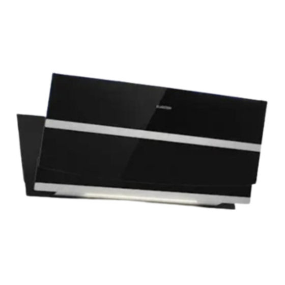
  • Seite 1 Dunstabzugshaube Range Hood Campana extractora Hotte aspirante Cappa aspirante 10033285...
  • Seite 3: Inhaltsverzeichnis

    Italiano 61 Installation 6 Bedienung 12 Reinigung und Wartung 14 Fehlersuche und Fehlerbehebung 15 Hinweise zur Entsorgung 15 TECHNISCHE DATEN Artikelnummer 10033285 Stromversorgung 220-240 V ~ 50/60 Hz KONFORMITÄTSERKLÄRUNG Hersteller: Chal-Tec GmbH, Wallstraße 16, 10179 Berlin, Deutschland. Dieses Produkt entspricht den folgenden Europäischen Richtlinien: 2014/30/EU (EMV)
  • Seite 4: Sicherheitshinweise

    SICHERHEITSHINWEISE • Lesen Sie sich alle Hinweise vor der Benutzung sorgfältig durch und bewahren Sie die Bedienungsanleitung zum späteren Nachschlagen gut auf. • Die Montagearbeiten dürfen nur von einem Elektrofachmann oder einer Fachkraft durchgeführt werden. Bevor Sie die Dunstabzugshaube verwenden, stellen Sie sicher, dass die Spannung (V) und die auf der Dunstabzugshaube angegebene Frequenz (Hz) der Spannung (V) und Frequenz (Hz) ihrer Stromversorgung entsprechen.
  • Seite 5 Wichtige Hinweise zum Abluftbetrieb WARNUNG: Vergiftungsgefahr durch zurückgesaugte Abgase! Betreiben Sie das Gerät nicht im Abluftbetrieb, wenn es zusammen mit einer raumluftabhängigen Feuerstätte betrieben wird und keine ausreichende Luftzirkulation garantiert wird. Raumluftabhängige Feuerstätten, wie Gas-, Öl-, Holz- oder Kohleheizungen, Boiler oder Durchlauferhitzer) beziehen die Luft aus dem Raum und führen Sie durch ein Abluftrohr oder eine Kamin ins Freie.
  • Seite 6: Installation

    INSTALLATION Vorbereitung • Falls sie über einen Abzug nach außen verfügen, können Sie die Abzugshaube wie auf dem Bild rechts installieren. Der Abzugskanal sollte einen Durchmesser von mindestens 150 mm haben und aus Emaille, Aluminium oder einem flexiblen, hitzebeständigen Rohr bestehen. •...
  • Seite 7 • Befestigen Sie das Seil an der Dunstabzugshaube: Drücken Sie dazu leicht auf die Spitzen der Kabelhalterungen und stecken Sie die Kabelenden hinein, sie werden automatisch fixiert. Passen Sie die Länge je nach Bedarf an. Hinweis: Die Kabel lassen sich nur justieren, indem Sie auf die Kabelhalterspitzen drücken.
  • Seite 8 • Heben Sie die Dunstabzugshaube an, befetigen Sie die Plattenabdeckungen mit 8 ST4*8 Schrauben an den Aufhängeplatten. Installation mit Schornstein Entfernen Sie zunächst die Abdeckung der Auslassöffnung von der Dunstabzugshaube. Halten Sie die Aufhängeplatte an die Decke und markieren Sie dann die Position der Schraubenlöcher.
  • Seite 9 Befestigen Sie die Winkelstangen mit 8 M5 Schrauben an der Aufhängeplatte. Verlängern Sie die Winkelstangen bis auf die gewünschte Höhe und fixieren Sie sie dann mit 16 M5 Schrauben. Hinweis: Die Winkelstangen müssen MINDESTENS 100 mm überlappen. M5 + Muttern M5 + Schrauben + Muttern Wenn Ihre Dunstabzugshaube im Absaugmodus betrieben werden soll, muss der Absaugschlauch an dieser Stelle mit dem Deckenanschluss verbunden werden.
  • Seite 10 Heben Sie das Gehäuse der Dunstabzugshaube auf die Winkelstange und befestigen Sie es mit 16 M5 Schrauben. Hinweis: • Dieser Montage-Schritt muss von zwei Personen vorgenommen werden. • Schrauben Sie die 16 M5 Schrauben gut fest! Entfernen Sie den Aufhängehaken und schieben Sie dann das untere Schornsteinteil nach unten, bis es am Gehäuse der Dunstabzugshaube anliegt.
  • Seite 11: Aktivkohlefilter Einbauen

    Installation mit Innenentlüftung Falls Sie nicht über einen Außenabzug verfügen, benötigen Sie kein Abluftrohr. Die Installation entspricht der Installation mit Außenentlüftung. Aktivkohlefilter einbauen Hinweis: Ein Aktivkohlefilter gehört nicht zum Lieferumfang. Sie können ihn aber zur Abzugshaube dazukaufen. Mit einem Aktivkohlefilter Um den Filter installieren zu lassen sich bei innenentlüfteten können, müssen sie zuerst den...
  • Seite 12: Bedienung

    BEDIENUNG Bedienfeld Wenn das Gerät eingeschaltet wird, wechselt es automatisch in den Standby- Modus. Timer-Taste • Zeiteinstellung: Drücken Sie im Standby-Modus die Timer-Taste, um die Zeit-Einstellung vorzunehmen. Die Stunden-Anzeige blinkt. Verwenden Sie die „+“oder „–“-Taste zum Einstellen. Drücken Sie die Timer-Taste, um in die Minuten-Einstellung zu gelangen.
  • Seite 13: Lcd-Display

    LCD-Display Das Lüfter-Symbol: wird angezeigt, wenn der Lüfter in Betrieb ist. Zeit-Anzeige Timer Licht Lüfter-Geschwindigkeit Alarm-Symbol Reinigungssymbol: erscheint bei einer Gesamtbetriebszeit von bis zu 14 Stunden oder bei Inbetriebnahme. RGB Standby-Modus / RGB ausschalten GRÜN BLAU WEISS MISCHFARBE = A1 + A2 + A3 •...
  • Seite 14: Reinigung Und Wartung

    Wenn der Motor und der RGB-Modus eingeschaltet sind: Wenn der Motor ausgeschaltet und der RGB-Modus eingeschaltet ist: REINIGUNG UND WARTUNG • Schalten Sie das Gerät vor der Reinigung aus und ziehen Sie den Netzstecker. Regelmäßige Reinigung • Verwenden Sie ein weiches Tuch, das mit handwarmem, mildem Seifenwasser oder Haushaltsreiniger befeuchtet ist.
  • Seite 15: Fehlersuche Und Fehlerbehebung

    FEHLERSUCHE UND FEHLERBEHEBUNG Fehler Mögliche Ursache Lösung Das Licht ist an aber der Die Lüftung ist blockiert. Entfernen Sie die Lüfter funktioniert nicht. Blockade. Der Motor ist kaputt. Lassen Sie den Motor ersetzen. Das Licht ist aus und der Das Licht ist kaputt. Lassen Sie das Licht Lüfter funktioniert nicht.
  • Seite 17: Technical Data

    Installation 20 Operation 26 Cleaning and Maintenance 28 Troubleshooting 29 Hints on Disposal 29 TECHNICAL DATA Item number 10033285 Power supply 220-240 V ~ 50/60 Hz DECLARATION OF CONFORMITY Producer: Chal-Tec GmbH, Wallstraße 16, 10179 Berlin, Germany. This product is conform to the following European...
  • Seite 18: Safety Instructions

    SAFETY INSTRUCTIONS • Thank you for purchasing this cooker hood. Please read the instruction manual carefully before you use the cooker hood, and keep it in a safe place. • The installation work must be carried out by a qualified electrician or competent person.
  • Seite 19 Important notes about the extraction mode WARNING: Risk of poisoning from exhaust gases sucked back! Never operate the device in extraction mode simultaneously with an open flue appliance when there is not adequate airflow guaranteed. Open flue combustion equipment (for example, gas, oil, wood or coal-fired heaters, tankless water heaters, water heaters) pulls combustion air from the room and runs it through an exhaust pipe or chimney to the outside.
  • Seite 20: Installation

    INSTALLATION Preparation • If you have an outlet to the outside, your cooker hood can be connected as below picture by means of an extraction duct (enamel, aluminium, flexible pipe or inflammable material with an interior diameter of 150 mm). • Before installation, turn the unit off and unplug it from the outlet.
  • Seite 21 • Attach the rope to the cooker hood: Press slightly the tips on the plate cable holders and insert the cable ends, they will be fixed automatically. Adjust the length as required. Note: The cables can only be adjusted by pressing on the cable holder tips. Insert out Press •...
  • Seite 22 • Lift the cooker hood, lock the plate covers with 8 ST4*8 screws to the hanging plates. Installation (Chimney kit) Firstly, remove the outlet cover from the cooker hood. Position the hanging plate on the ceiling and then mark the position of the screw holes.
  • Seite 23 Fix the angle bars with 8 M5 screws to the hanging plate. Extend the angle bars to the required height and then fix them with 16 M5 screws. Note: The angle bars must have an overlap of AT LEAST 100 mm. M5 + nuts M5 + screws + nuts If your cooker hood is going to be used in extraction mode, the ducting hose must...
  • Seite 24 Lift the main body of the cooker hood onto the angle bar and fix it into position with 16 M5 screws. Note: • This installation step must be carried out by two persons. • The 16 M5 screws must be securely tightened. Remove the hanging hook and then slide the lower chimney section downwards, until it rests against the main body of the cooker hood.
  • Seite 25 Installation (Vent inside) If you do not have an outlet to the outside, exhaust pipe is not required and the installation is similar to the one shown in section “Installation (Vent outside)”, except the chimney assemble. Installing the Carbon Filter Note: An activated carbon filter is not included.
  • Seite 26: Operation

    OPERATION Control panel When the power is turned on, the unit automatically switches to standby mode. Timer button • Time setting: in standby mode, press the timer button to set the time. The hour display flashes. Use the “+“ or „–“ button to set the time. Press the Timer button to change the minute setting.
  • Seite 27 LCD display The Fan symbol, will turn on when the fan is working. Time display Timer Light Fan speed Alarm symbol Cleaning symbol: appears when the total working time is up to 14 hours or during start-up. RGB standby mode / turn off the RGB GREEN BLUE WHITE...
  • Seite 28: Cleaning And Maintenance

    When the motor and the RGB is on: When the motor is off and the RGB is on: CLEANING AND MAINTENANCE • Before cleaning switch the unit off and pull out the plug. Regular Cleaning • Use a soft cloth moistened with hand-warm mildly soapy water or household cleaning detergent.
  • Seite 29: Troubleshooting

    TROUBLESHOOTING Fault Possible Cause Solution Light on, but the fan does The leaf is blocked. Get rid of the blocking. not work. The motor is damaged. Replace the motor. Both light and fan do not The Light is damaged. Replace the lights. work Power cord looses.
  • Seite 31: Fiche Technique

    Utilisation 42 Nettoyage et maintenance 44 Identification et résolution des problèmes 45 Informations sur le recyclage 45 FICHE TECHNIQUE Numéro d'article 10033285 Alimentation 220-240 V ~ 50/60 Hz DÉCLARATION DE CONFORMITÉ Fabricant : Chal-Tec GmbH, Wallstraße 16, 10179 Berlin, Allemagne. Ce produit est conforme aux directives européennes...
  • Seite 32: Consignes De Sécurité

    CONSIGNES DE SÉCURITÉ • Lisez attentivement toutes les instructions avant utilisation et conservez le mode d‘emploi pour vous y référer ultérieurement. • Les travaux d‘assemblage ne doivent être effectués que par un électricien qualifié ou un spécialiste. Avant d‘utiliser la hotte, assurez-vous que la tension (V) et la fréquence (Hz) indiquées sur la hotte correspondent à...
  • Seite 33 Conseils importants pour l‘utilisation en extraction d‘air MISE EN GARDE :: Danger d‘intoxication par inhalation des gaz d‘échappement ! Ne faites pas fonctionner l‘appareil en mode extraction d‘air s‘il est utilisé avec un foyer consommant l‘oxygène de l‘air ambiant et qu‘il n‘y a aucune garantie de circulation d‘air suffisante.
  • Seite 34: Installation

    INSTALLATION Préparation • Si vous disposez d‘une extraction d‘air vers l‘extérieur, vous pouvez installer la hotte aspirante comme illustré sur la figure de droite. Le conduit d‘extraction doit avoir un diamètre d‘au moins 150 mm et être en émail, aluminium ou en matériau souple résistant à...
  • Seite 35 • Fixez le câble à la hotte : appuyez légèrement sur les pointes des serre-câbles et insérez les extrémités du câble, elles sont automatiquement fixées. Ajustez la longueur au besoin. Remarque : Les câbles ne peuvent être ajustés qu’en appuyant sur les extrémités de leurs supports.
  • Seite 36 • Soulevez la hotte, fixez les couvercles des plaques aux plaques de suspension avec 8 vis ST4 * 8. Installation avec cheminée Commencez par retirer le couvercle de l‘ouverture de sortie de la hotte. Tenez la plaque de suspension au plafond, puis marquez la position des trous de vis.
  • Seite 37 Fixez les cornières à la plaque de suspension avec 8 vis M5. Rallongez les cornières à la hauteur souhaitée et fixez-les avec 16 vis M5. Remarque : les cornières doivent se chevaucher de 100 mm AU MOINS. M5 + écrous M5 + vis + écrous Si votre hotte doit fonctionner en mode d‘extraction, c‘est à...
  • Seite 38 Soulevez le boîtier de la hotte sur la cornière et fixez-le avec 16 vis M5. Remarque: • Cette étape du montage doit être réalisée par deux personnes. • Vissez bien les 16 vis M5 ! Retirez le crochet de suspension, puis faites glisser la partie inférieure de la cheminée vers le bas jusqu‘à...
  • Seite 39 Installation avec ventilation intérieure Si vous n‘avez pas de canalisation d‘extraction externe, vous n‘avez pas besoin de conduit d‘extraction. L‘installation correspond à l‘installation avec ventilation externe. Installation du filtre à charbon actif Remarque : Le filtre à charbon actif n‘est pas inclus. Mais vous pouvez le commander avec la hotte.
  • Seite 40: Utilisation

    UTILISATION Panneau de commande Lorsque vous allumez l‘appareil, il passe automatiquement en mode veille. Touche de minuterie • Réglage de la durée : En mode veille, appuyez sur la touche de la minuterie pour régler la durée. L‘indicateur des heures clignote. Utilisez la touche „+“...
  • Seite 41 Ecran LCD Symbole de ventilation : s‘affiche lorsque la ventilation fonctionne. Affichage de la durée Minuterie Eclairage Vitesse de ventilation Symbole de l‘alarme Symbole de nettoyage : apparaît au bout d‘une durée totale d‘utilisation de 14 heures ou à la mise en marche. veille du mode RGB / arrêt du mode RGB ROUGE VERT...
  • Seite 42: Nettoyage Et Maintenance

    Lorsque le moteur et le mode RVB sont activés: Lorsque le moteur est désactivé et que le mode RVB est activé : NETTOYAGE ET MAINTENANCE • Éteignez l‘appareil avant de le nettoyer et débranchez la fiche. Nettoyage courant • Utilisez un chiffon doux imprégné d’eau tiède, d’eau savonneuse ou de détergent ménager.
  • Seite 43: Identification Et Résolution Des Problèmes

    IDENTIFICATION ET RÉSOLUTION DES PROBLÈMES Problème Cause possible Solution L'éclairage est allumé La ventilation est bloquée. Supprimer le blocage. mais le ventilateur ne Le moteur est cassé. Faites remplacer le moteur. fonctionne pas. L'éclairage est éteint et le L'éclairage est hors Faites remplacer ventilateur ne fonctionne service.
  • Seite 45: Datos Técnicos

    Manejo 56 Limpieza y mantenimiento 58 Búsqueda de errores y solución de problemas 59 Retirada del aparato 59 DATOS TÉCNICOS Número de artículo 10033285 Alimentación 220-240 V ~ 50/60 Hz DECLARACIÓN DE CONFORMIDAD Fabricante: Chal-Tec GmbH, Wallstraße 16, 10179 Berlín, Alemania. Este producto cumple con las siguientes directivas...
  • Seite 46: Instrucciones De Seguridad

    INSTRUCCIONES DE SEGURIDAD • Lea atentamente todas las instrucciones antes del uso y guarde el manual de instrucciones en un lugar seguro para poder consultarlo en el futuro. • Los trabajos de montaje sólo pueden ser realizados por un electricista o un especialista.
  • Seite 47 Indicaciones importantes para la campana en modalidad aspirante ATENCIÓN Peligro de intoxicación por gases de escape aspirados! No utilice la unidad en modalidad aspirante si se utiliza junto con una chimenea dependiente del aire y si no está garantizada una circulación de aire suficiente.
  • Seite 48 INSTALACIÓN Preparación • Si tiene una campana extractora de humos en el exterior, puede instalarla como se muestra en la imagen de la derecha. El canal de desagüe debe tener un diámetro mínimo de 150 mm y ser de esmalte, aluminio o un tubo flexible y resistente al calor.
  • Seite 49 • Sujete el cable a la campana extractora: Presione ligeramente las puntas de los soportes e inserte los extremos de los cables, se fijarán automáticamente. Ajuste la longitud según sea necesario. Nota: Los cables sólo se pueden ajustar presionando en las puntas de los soportes de cables.
  • Seite 50 • Levante la campana extractora y fije las tapas de las placas a las placas de suspensión con 8 tornillos ST4*8. Instalación con chimenea Retire primero la cubierta de salida de la campana extractora. Sujete la placa de suspensión contra el techo y, a continuación, marque la posición de los orificios de los tornillos.
  • Seite 51 Fije las barras angulares a la placa de suspensión con 8 tornillos M5. Extienda las barras angulares a la altura deseada y fíjelas con 16 tornillos M5. Nota: Las barras angulares deben solaparse al menos 100 mm. M5 + tuercas M5 + tornillos + tuercas Si su campana extractora se va a utilizar en el modo de aspiración, la manguera de aspiración debe estar conectada en este punto a la conexión del techo.
  • Seite 52 Levante la carcasa de la campana extractora sobre la barra angular y fíjela con 16 tornillos M5. Nota: • Este paso de montaje debe ser realizado por dos personas. • Apriete bien los 16 tornillos M5! Retire el gancho de suspensión y, a continuación, empuje la parte inferior de la chimenea hacia abajo hasta que se apoye en la carcasa de la campana extractora.
  • Seite 53 Instalación con ventilación interna Si no tiene una campana de extracción externa, no necesita un conducto de extracción. La instalación corresponde a la instalación con ventilación externa. Instalación del filtro de carbón activado Atención: No está incluido un filtro de carbón activado (número de artículo 10032842).
  • Seite 54 MANEJO Panel de control Cuando la unidad se enciende, cambia automáticamente al modo de espera. Botón del temporizador • Ajuste de la hora: En el modo de espera, pulse el botón del temporizador para ajustar la hora. La indicación de la hora parpadea. Utilice los botones „+“...
  • Seite 55 Indicador LCD El icono del ventilador: aparece cuando el ventilador está en marcha. Visualización de la hora Temporizador Velocidad del ventilador Ícono de alarma Símbolo de limpieza: aparece durante un tiempo de funcionamiento total de hasta 14 horas o durante la puesta en marcha. Desactivar el modo de espera RGB / apagar RGB ROJO VERDE...
  • Seite 56: Limpieza Y Mantenimiento

    Cuando el motor y el modo RGB están encendidos : Cuando el motor está apagado y el modo RGB está encendido : LIMPIEZA Y MANTENIMIENTO • Apague el aparato antes de limpiarlo y desenchúfelo de la red eléctrica. Limpieza regular •...
  • Seite 57: Retirada Del Aparato

    BÚSQUEDA DE ERRORES Y SOLUCIÓN DE PROBLEMAS Error Posible causa Solución del problema La luz se enciende pero el La pala del ventilador Elimine el bloqueo. ventilador no funciona. está rota. El motor está dañado. Sustituya el motor. La luz está apagada y el La bombilla se ha fundido.
  • Seite 59: Dati Tecnici

    Installazione 64 Funzionamento 70 Pulizia e manutenzione 72 Risoluzione dei problemi 73 Smaltimento 73 DATI TECNICI Numero di articolo 10033285 Alimentazione 220-240 V ~ 50/60 Hz DICHIARAZIONE DI CONFORMITÀ Produttore: Chal-Tec GmbH, Wallstraße 16, 10179 Berlin, Germany. Questo prodotto è conforme alle seguenti direttive europee:...
  • Seite 60: Istruzioni Di Sicurezza

    ISTRUZIONI DI SICUREZZA • Leggere attentamente tutte le istruzioni prima dell‘uso e conservare il manuale per riferimenti futuri. • I lavori di montaggio devono essere eseguiti esclusivamente da un elettricista o uno specialista qualificato. Prima di utilizzare la cappa aspirante, assicurarsi che la tensione (V) e la frequenza (Hz) indicate sulla cappa da cucina corrispondano alla tensione (V) e alla frequenza (Hz) dell‘alimentatore.
  • Seite 61 Suggerimenti importanti sul funzionamento dell‘aria di scarico AVVERTENZA Pericolo di avvelenamento dovuto a gas di scarico aspirati! Non utilizzare l‘unità in modalità di estrazione dell‘aria se il dispositivo viene utilizzato insieme ad un caminetto dipendente dall‘aria ambiente e non vi è garanzia di una circolazione sufficiente dell‘aria. I camini dipendenti dall‘aria, come gli impianti di riscaldamento a gas, olio, legna o carbone, caldaie o scaldabagni) attirano l‘aria fuori dalla stanza e la conducono all‘aria aperta attraverso un tubo di scarico o un camino.
  • Seite 62 INSTALLAZIONE Preparazione • Se si dispone di uno sfiato verso l‘esterno, è possibile installare la cappa aspirante come mostrato nella figura a destra. Il condotto di estrazione deve avere un diametro di almeno 150 mm ed essere realizzato in smalto, alluminio o un tubo flessibile resistente al calore.
  • Seite 63 • Attaccare la fune alla cappa aspirante: premere leggermente sulla punta dei fermacavo e inserire le estremità del cavo che si fissano automaticamente. Regolare la lunghezza secondo necessità. Nota: i cavi possono essere regolati solo premendo le punte del portacavo. Inserire il Premere cavo...
  • Seite 64 • Sollevare la cappa, fissare i coperchi delle piastre alle piastre di sospensione con 8 viti ST4 * 8. Installazione con camino Innanzitutto, rimuovere il coperchio di uscita dalla cappa aspirante. Tenere la piastra di sospensione sul soffitto e quindi contrassegnare la posizione dei fori delle viti.
  • Seite 65 Attaccare le aste angolari alla piastra di sospensione con 8 viti M5. Estendere le barre angolari all‘altezza desiderata e fissarle con 16 viti M5. Nota: le barre angolari devono sovrapporsi di almeno 100 mm. M5 + viti M5 + viti + dadi Se la cappa aspirante deve essere utilizzata nella modalità...
  • Seite 66 Sollevare la custodia della cappa sulla barra angolare e fissarla con 16 viti M5. Nota: • Questa fase di assemblaggio deve essere eseguita da due persone. • Stringere saldamente le 16 viti M5! Rimuovere il gancio di sospensione e quindi far scorrere la sezione inferiore del camino verso il basso finché...
  • Seite 67 Installazione con ventilazione interna Se non si dispone di uno scarico esterno, non è necessario un tubo di scarico. L‘installazione corrisponde all‘installazione con ventilazione esterna. Installazione del filtro a carbone attivo Nota: il filtro a carbone attivo non è incluso nella consegna. È possibile comprarlo in aggiunta alla cappa aspirante.
  • Seite 68 FUNZIONAMENTO Pannello di controllo Quando l‘unità è accesa, passa automaticamente alla modalità standby. Tasto-Timer • Impostazione del tempo: in modalità standby, premere il pulsante del timer per impostare l‘ora. L‘indicatore dell‘ora lampeggia. Utilizzare il pulsante „+“ o „-“ per regolare. Premere il pulsante del timer per accedere all‘impostazione dei minuti.
  • Seite 69 Display LCD L‘icona della ventola: viene visualizzata quando la ventola è in funzione. Indicatore del tempo Timer Luce Velocità della ventola Simbolo di allarme Simbolo pulizia: appare per un tempo di funzionamento totale fino a 14 ore o alla messa in servizio. Disattiva la modalità...
  • Seite 70: Pulizia E Manutenzione

    Quando il motore e la modalità RGB sono accesi : Quando il motore è spento e la modalità RGB è accesa : PULIZIA E MANUTENZIONE • Spegnere il dispositivo prima di pulire e scollegare la spina di alimentazione. Pulizia regolare •...
  • Seite 71: Risoluzione Dei Problemi

    RISOLUZIONE DEI PROBLEMI Errore Possibile causa Soluzione La luce è accesa ma la La ventola è bloccata. Rimuovere il blocco. ventola non funziona. Il motore è rotto. Far sostituire il motore. La luce è spenta e la La luce è rotta. Far sostituire la luce.

Inhaltsverzeichnis