
Verwandte Anleitungen für PARKZONE P-51D MUSTANG BL RTF


Inhaltszusammenfassung für PARKZONE P-51D MUSTANG BL RTF
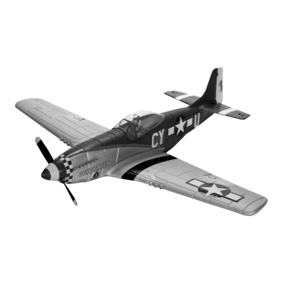
- Seite 1 P-51D MUSTANG BL Instruction Manual • Bedienungsanleitung • Manuel d’utilisation • Manuale di Istruzioni...
-
Seite 2: Meaning Of Special Language
NOTICE All instructions, warranties and other collateral documents are subject to change at the sole discretion of Horizon Hobby, Inc. For up-to-date product literature, visit www.horizonhobby.com and click on the support tab for this product. Meaning of Special Language: The following terms are used throughout the product literature to indicate various levels of potential harm when operating this product: NOTICE: Procedures, which if not properly followed, create a possibility of physical property damage AND little or no possibility of injury. CAUTION: Procedures, which if not properly followed, create the probability of physical property damage AND a possibility of serious injury. WARNING: Procedures, which if not properly followed, create the probability of property damage, collateral damage, and serious injury OR create a high probability of superficial injury. WARNING: Read the ENTIRE instruction manual to become familiar with the features of the product before operating. Failure to operate the product cor- rectly can result in damage to the product, personal property and cause serious injury. This is a sophisticated hobby product. It must be operated with caution and common sense and requires some basic mechanical ability. Failure to operate this Product in a safe and responsible manner could result in injury or damage to the product or other property. This product is not intended for use by children without direct adult supervision. Do not attempt disassembly, use with incompatible components or augment product in any way without the approval of Horizon Hobby, Inc. This manual contains instructions for safety, operation and maintenance. It is essential to read and follow all the instructions and warnings in the manual, prior to assembly, setup or use, in order to operate correctly and avoid damage or serious injury. Additional Safety Precautions and Warnings As the user of this product, you are solely responsible for operating in a manner that does not endanger yourself and others, or result in damage to the product or the property of others. -
Seite 3: Inhaltsverzeichnis
Installing the Flight Battery ............... 6 FCC Information ................13 Center of Gravity (CG) ............... 6 Compliance Information Installing Clevises on Control Horns and Control Centering ....7 for the European Union ..............13 Factory Settings ................7 Parts Contact Information ............... 14 Control Direction Test ................ 7 Replacement Parts ................47 First Flight Preparation ..............8 To register your product online, visit www.parkzone.com... -
Seite 4: Charging The Flight Battery
• Charges 3-cell lithium polymer battery packs charger only (such as the included charger). Never leave the battery and char- • 1-amp charge rate ger unattended during the charge process. Failure to follow the instructions • LED charge status indicator properly could result in a fire. When charging, make certain the battery is on a • 12V accessory outlet input cord heat-resistant surface. Charge the flight battery while assembling the aircraft. Install the fully charged battery to perform control tests and binding. Specifications • Input power: 12V DC, 3-amp • Charges 3-cell Li-Po packs with minimum capacity of 1000mAh 3S 11.1V 1300mAh 25C Li-Po Battery Pack (PKZ1033) The ParkZone 3S Li-Po battery pack features a balancing lead ® that allows you to safely charge your battery pack when used with the included ParkZone Li-Po balancing charger. The Battery Charging Process Charge only batteries that are cool to the touch and are not damaged. Look at the battery to make sure it is not damaged e.g., swollen, bent, broken or punctured. Attach the input cord of the charger to the appropriate power supply (12V accessory outlet). Connect the balancing lead of the battery to the charger port. The LED will continually blink while the battery charges. Charging is complete when the LED indicator shines continuously. Always unplug the battery from the charger immediately upon completion of charging. CAUTION: Overcharging a battery can cause a fire. -
Seite 5: Installing Horizontal Tail
Installing Horizontal Tail 1. Install the horizontal stabilizer in the fuselage mount. 2. Apply 4 pieces of tape (total) on the top and bottom of horizontal tail at the fuselage mount. 3. Attach clevis to elevator control horn. 4. When needed, disassemble in reverse order. Top of Tail Tape (4 pcs.) Installing Transmitter Batteries Low Battery Alarm The DX4e requires 4 AA alkaline, heavy-duty or rechargeable batteries. Remove the battery door and install 4 AA batteries. Make sure the polarity When the battery voltage drops below 4.7 volts, an alarm sounds and the volt- of each battery corresponds with the diagram in the battery holder. age LEDs flash. The batteries must be replaced immediately. If this happens Replace the battery door. while flying, land your aircraft as soon and as safely as possible. Transmitter and Receiver Binding Binding is the process of programming the receiver of the control unit to recognize the GUID (Globally Unique Identifier) code of a single specific transmitter. You need to ‘bind’ your chosen Spektrum DSM2 /DSMX technology equipped aircraft transmitter to the receiver for proper operation. ™... -
Seite 6: Before Flight
Before Flight Power on Wait 5 • Lower throttle and • Connect battery to ESC. Continuous LED Transmitter seconds throttle trim to Series of tones lowest settings. Installing the Flight Battery 1. Remove the canopy from the fuselage. 2. Loosen the hook and loop strap. 3. Put the fully charged battery in the battery cavity in the fuselage. 4. Tighten the hook and loop strap around the battery. 5. Connect the EC3 battery connector to the ESC power connector only when preparing to fly the model. 6. Put the canopy pins in the fuselage, align the canopy with the fuselage and close the canopy. NOTICE: Always disconnect the Li-Po battery from the ESC of the air- craft when not flying. Failure to do so will render the battery unusable. CAUTION: Always keep hands away from propeller. When armed, the motor will turn the propeller in response to any throttle movement. Center of Gravity (CG) Install included battery in the fuselage using the hook and loop straps. Low Rate High Rate Aileron: 1/4 inch (6.4mm) 3/8 inch (9.5mm) Elevator: 1/4 inch (6.4mm) -
Seite 7: Installing Clevises On Control Horns And Control Centering
Installing Clevises on Control Horns and Control Centering Tip: Turn the clevis clockwise or counterclockwise on the linkage. • Pull the tube from the clevis to the linkage. • Carefully spread the clevis and put the clevis pin in a selected hole in the control horn. • Move the tube to hold the clevis on the control horn. After binding a transmitter to model receiver, set trims and sub-trims to 0, then adjust clevises to center control surfaces. Factory Settings Ailerons Ailerons Rudders Rudders Arms Horns Fly the model at factory settings before making changes. For pilots who wish to fly model for advanced aerobatics, adjust position of linkages Arms Arms on control horns for increased travel. Ailerons Elevators Ailerons Elevators Control Direction Test Horns Horns... -
Seite 8: First Flight Preparation
To land, fly the aircraft down using 1/4 to 1/3 throttle and bring it in directly the wind, even in a light breeze. into the wind. Prior to touch down, reduce throttle completely and flare the nose up to avoid damage to the propeller and other components. Hand Launching Repairs To hand launch the P-51 Mustang BL, hold the airplane on the underside of the fuselage. While giving the transmitter full throttle, give a firm throw directly Thanks to the Z-Foam construction of the P-51 Mustang BL, repairs to the ™ into the wind slightly up (5–10 degrees above the horizon). foam can be made using virtually any adhesive (hot glue, regular CA, epoxy, etc). When parts are not repairable, see the Replacement Parts List for Flying ordering by item number. NOTICE: Use of CA accelerant on your model can damage paint. Always choose a wide-open space for flying your ParkZone P-51 Mustang BL. DO NOT wipe accelerant from model. Let accelerant evaporate. It is ideal for you to fly at a sanctioned flying field. If you are not flying at an approved site, always avoid flying near houses, trees, wires and buildings. You Note: When making repairs to the horizontal stab, foam safe CA must be used. should also be careful to avoid flying in areas where there are many people, such as busy parks, schoolyards, or soccer fields. Consult local laws and ordinances before choosing a location to fly your aircraft. Fly in this area (upwind of pilot). Stand here. -
Seite 9: Maintenance After Flying
Maintenance After Flying • Disconnect flight battery from ESC (Required for Safety and battery life) • Repair or replace all damaged parts • Power off transmitter • Store flight battery apart from aircraft and monitor the battery charge • Remove flight battery from aircraft • Make note of flight conditions and flight plan results, • Recharge flight battery planning for future flights AMA National Model Aircraft Safety Code B. RADIO CONTROL Effective January 1, 2011 A. GENERAL 1. All pilots shall avoid flying directly over unprotected people, vessels, A model aircraft is a non-human-carrying aircraft capable of sustained flight vehicles or structures and shall avoid endangerment of life and property of in the atmosphere. It may not exceed limitations of this code and is intended others. exclusively for sport, recreation and/or competition. All model flights must 2. A successful radio equipment ground-range check in accordance with be conducted in accordance with this safety code and any additional rules manufacturer’s recommendations will be completed before the first flight specific to the flying site. -
Seite 10: Troubleshooting Guide
Troubleshooting Guide Problem Possible Cause Solution Aircraft will not respond Throttle not at idle and/or throttle trim too high Reset controls with throttle stick and throttle trim to throttle but responds to at lowest setting other controls Throttle servo travel is lower than 100% Make sure throttle servo travel is 100% or greater Throttle channel is reversed Reverse throttle channel on transmitter Extra propeller noise or Damaged propeller and spinner, collet or motor Replace damaged parts extra vibration Propeller is out of balance Balance or replace propeller Reduced flight time or air- Flight battery charge is low Completely recharge flight battery craft underpowered Propeller installed backwards Install propeller with numbers facing forward Flight battery damaged Replace flight battery and follow flight battery instructions Flight conditions may be too cold Make sure battery is warm before use... -
Seite 11: Optional Rudder
Optional Rudder The P-51D Mustang BL has the option to make the rudder functional. The pushrod and control horn are included with the airplane and all that is required is one additional servo. 1. T o install the rudder servo into the fuselage, glue the servo (PKZ1080 SV80 Short Lead 3-Wire Servo) in the servo pocket with silicone adhesive, epoxy or hot glue with the output spline facing forward. 2. S lide the pushrod into the fuselage with the “Z” bend facing forward. 3. U sing a hobby knife, cut around the counterbalance at the top of the rudder and cut away the brace at the bottom of the rudder. 4. Place the control horn so that the holes that the clevis attaches to is over the hinge line of the rudder. Using a small drill bit or sharpned piece of wire, make the holes through the rudder for the control horn screws. Place the backplate of the control horn on the opposite side of the rudder and use a Phillips screwdriver to tighten the screws holding the rudder control horn in place. Only tighten the screws until they just start to compress the foam, taking care not to overtighten them. -
Seite 12: Warranty And Repair Policy
Warranty and Repair Policy What this Warranty Covers Warranty Services Questions, Assistance, and Repairs Horizon Hobby, Inc. (“Horizon”) warrants to the original purchaser that the product purchased (the “Product”) will be free from defects in materials Your local hobby store and/or place of purchase cannot provide warranty and workmanship at the date of purchase. support or service. Once assembly, setup or use of the Product has been started, you must contact Horizon directly. This will enable Horizon to better What is Not Covered answer your questions and service you in the event that you may need any This warranty is not transferable and does not cover (i) cosmetic damage, (ii) assistance. For questions or assistance, please direct your email to product- damage due to acts of God, accident, misuse, abuse, negligence, commercial support@horizonhobby.com, or call 877.504.0233 toll free to speak to use, or due to improper use, installation, operation or maintenance, (iii) modi- a Product Support representative. You may also find information on fication of or to any part of the Product, (iv) attempted service by anyone other our website at www.horizonhobby.com. than a Horizon Hobby authorized service center, or (v) Products not purchased from an authorized Horizon dealer. Inspection or Services OTHER THAN THE EXPRESS WARRANTY ABOVE, HORIZON MAKES NO OTHER If this Product needs to be inspected or serviced, please use the Horizon Online WARRANTY OR REPRESENTATION, AND HEREBY DISCLAIMS ANY AND ALL Service Request submission process found on our website or call Horizon to IMPLIED WARRANTIES, INCLUDING, WITHOUT LIMITATION, THE IMPLIED WAR-... -
Seite 13: Contact Information
Contact Information Country of Purchase Horizon Hobby Address Phone Number/Email Address 4105 Fieldstone Rd 877-504-0233 Horizon Service Center Champaign, Illinois Online Repair Request: (Electronics and engines) 61822 USA visit www.horizonhobby.com/repairs United States of America 4105 Fieldstone Rd Horizon Product Support 877-504-0233 Champaign, Illinois (All other products) productsupport@horizonhobby.com 61822 USA Units 1-4 Ployters Rd Staple Tye +44 (0) 1279 641 097 United Kingdom Horizon Hobby Limited Harlow, Essex sales@horizonhobby.co.uk CM18 7NS United Kingdom Hamburger Str. 10 +49 4121 46199 66 Germany Horizon Technischer Service 25335 Elmshorn service@horizonhobby.de Germany 14 Rue Gustave Eiffel +33 (0) 1 60 47 44 70... -
Seite 14: Parts Contact Information
Parts Contact Information Country of Purchase Horizon Hobby Address Phone Number/Email Address 4105 Fieldstone Rd United States of 800-338-4639 Sales Champaign, Illinois America Sales@horizonhobby.com 61822 USA Units 1-4 Ployters Rd Staple Tye +44 (0) 1279 641 097 United Kingdom Horizon Hobby Limited Harlow, Essex sales@horizonhobby.co.uk CM18 7NS United Kingdom Hamburger Str. 10 +49 4121 46199 60 Germany Horizon Technischer Service 25335 Elmshorn service@horizonhobby.de Germany 14 Rue Gustave Eiffel +33 (0) 1 60 47 44 70 France Horizon Hobby SAS Zone d’Activité du Réveil Matin infofrance@horizonhobby.com 91230 Montgeron... -
Seite 15: Spezielle Bedeutungen
HINWEIS Alle Anweisungen, Garantien und anderen zugehörigen Dokumente können im eigenen Ermessen von Horizon Hobby, Inc. jederzeit geändert werden. Die aktuelle Produktliteratur finden Sie auf www.horizonhobby.com unter der Registerkarte „Support“ für das betreff ende Produkt. Spezielle Bedeutungen: Die folgenden Begriffe werden in der gesamten Produktliteratur verwendet, um auf unterschiedlich hohe Gefahrenrisiken beim Betrieb dieses Produkts hinzuweisen: HINWEIS: Wenn diese Verfahren nicht korrekt befolgt werden, können sich möglicherweise Sachschäden UND geringe oder keine Gefahr von Verletzungen ergeben. - Seite 16 Herzlichen Glückwunsch! Sie sind nur ein paar Minuten von dem sagenhaften Flugerlebnis der ParkZone P‑51 Mustang BL entfernt. Ihre Parkzone P‑51D Mustang BL bietet ihnen hohes Tempo und beste Steigleistung, die vom Kunstflug bis Verfolgungsjagden alles möglich macht. Die große Leistung des Flugzeuges erfordert es, dass Sie diese Anleitung vor dem ersten Flug sorgfältig lesen und beachten.
-
Seite 17: Laden Des Flugakkus
Der ParkZone 3S LiPo Akku ist mit einem Balancer Anschluß ausgestattet, ® der eine sichere Aufladung mit dem ParkZone LiPo Balancer Ladegerät ermöglicht. Der Akkuladevorgang Laden Sie nur Akkus die nicht zu heiß zum Anfassen und nicht beschädigt sind. Überprüfen Sie den Akku auf Beschädigungen, Schwellungen, Biegun‑... -
Seite 18: Montage Des Höhenruders
Montage des Höhenruders 1. Schieben Sie das Ruder vorsichtig durch den Schlitz im Seitenleitwerk. Zentrieren Sie das Höhenruder. 2. Sichern Sie wie abgebildet das Höhenruder auf der Ober‑ und Unterseite mit einem Stück klaren Klebeband. 3. Verbinden Sie den Gabelkopf mit dem Ruderhorn des Höhenruders. 4. -
Seite 19: Vor Dem Flug
Vor dem Flug Sender 5 Sekunden • Gashebel und Gastrim‑ • Flugakku mit Regler Kontinuierliche LED einschalten warten mung auf niedrigste (ESC) verbinden. Serie von Tönen Einstellung einstellen. Einsetzen des Flugakkus 1. Nehmen Sie die Kabinenhaube vom Rumpf ab. 2. Öffnen Sie die Klettschlaufen. 3. -
Seite 20: Einsetzen Der Gabelköpfe Und Zentrieren Der Kontrollen
Einsetzen der Gabelköpfe und Zentrieren der Kontrollen Tipp: Drehen Sie den Gabelkopf am Anschluss im Uhrzeigersinn oder entgegen dem Uhrzeigersinn. • Ziehen Sie das Silikonband vom Gabelkopf zum Anschluss. • Spreizen Sie den Gabelkopf vorsichtig auf, und setzen Sie den Pin in ein ausgewähltes Loch im Steuerhorn. -
Seite 21: Vorbereitung Für Den Erstflug
Vorbereitung für den Erstflug • Entnehmen und Inspizieren Sie alle Teile • Stellen Sie sicher, dass alle Anlenkungen frei laufen • Laden Sie den Flugakku • Führen Sie mit dem Sender eine Funktionskontrolle durch • Lesen Sie diese Anleitung sorgfältig •... -
Seite 22: Einbau Des Optionalen Seitenruders
Einbau des optionalen Seitenruders Die P‑51D Mustang bietet die Möglichkeit das Seitenruder anzusteuern. Dazu ist das Gestänge und Steuerhorn schon im Lieferumfang enthalten. Benötigt wird noch ein zusätzliches Servo. 1. Kleben Sie bitte ein Servo ( PKZ1080 SV80) in die Servoaussparung neben dem Höhenruderservo. -
Seite 23: Garantie Und Service Informationen
Garantie und Service Informationen Warnung Sicherheitshinweise Ein ferngesteuertes Modell ist kein Spielzeug. Es kann, wenn es falsch eing‑ Dieses ist ein hochwertiges Hobby Produkt und kein Spielzeug. Es muss mit esetzt wird,zu erheblichen Verletzungen bei Lebewesen und Beschädigungen Vorsicht und Umsicht eingesetzt werden und erfordert einige mechanische wie an Sachgütern führen. -
Seite 24: Rechtliche Informationen Für Die Europäische Union
erklärt das Produkt: Celectra 4-FachLi-Po Lader, Celectra 4-Fach Li-Po Lader mit230V Netzteil(EFLC1004, EFLC1004AC) declares the product: Celectra 4 Port Li-Po Charger, Celectra 4 Port Li-Po Charger with AC adapter(EFLC1004, EFLC1004AC) Rechtliche Informationen für die Europäische Union im Einklang mit den Anforderungen der unten aufgeführten Bestimmungen nach den Bestimmungen der europäischen EMV-Richtlinie 2004/108/EG und 2006/95/EG LVD: The object of declaration described above is in conformity with the requirements of the specifications listed below, following the provisions of Konformitätserklärung... -
Seite 25: Avertissements Relatifs À La Batterie
REMARQUE La totalité des instructions, garanties et autres documents est sujette à modification à la seule discrétion d’Horizon Hobby, Inc. Pour obtenir la documentation à jour, rendez-vous sur le site www.horizonhobby.com et cliquez sur l’onglet de support de ce produit. Signification de certains termes spécifiques : Les termes suivants sont utilisés dans l’ensemble du manuel pour indiquer différents niveaux de danger lors de l’utilisation de ce produit : REMARQUE : p rocédures qui, si elles ne sont pas suivies correctement, peuvent entraîner des dégâts matériels ET potentiellement un risque faible de blessures. ATTENTION : procédures qui, si elles ne sont pas suivies correctement, peuvent entraîner des dégâts matériels ET des blessures graves. AVERTISSEMENT : p rocédures qui, si elles ne sont pas suivies correctement, peuvent entraîner des dégâts matériels et des blessures graves OU engendrer une probabilité élevée de blessure superficielle. AVERTISSEMENT: lisez la TOTALITÉ du manuel d’utilisation afin de vous familiariser avec les caractéristiques du produit avant de le faire fonctionner. Une utilisation incorrecte du produit peut entraîner l’endommagement du produit lui-même, ainsi que des risques de dégâts matériels, voire de blessures graves. Ceci est un produit de loisirs sophistiqué. Il doit être manipulé avec prudence et bon sens et requiert des aptitudes de base en mécanique. Toute utilisation de ce produit ne respectant pas les principes de sécurité et de responsabilité peut entraîner des dégâts matériels, endommager le produit et provoquer des blessures. Ce produit n’est pas destiné à être utilisé par des enfants sans la surveillance directe d’un adulte. N’essayez pas de démonter le produit, de l’utiliser avec des composants incompatibles ou d’en améliorer les performances sans l’accord d’Horizon Hobby, Inc. Ce manuel comporte des instructions relatives à la sécurité, au fonctionnement et à l’entretien. Il est capital de lire et de respecter toutes les instructions et tous les avertissements du manuel avant l’assemblage, le réglage ou l’utilisation afin de manipuler correctement l’appareil et d’éviter tout dégât matériel ainsi que toute blessure grave. Précautions supplémentaires de sécurité L’utilisateur est le seul responsable des conséquences de l’utilisation du produit, il ne doit pas mettre les personnes et les biens en danger lors de l’utilisation. 14 ans et plus. - Seite 26 Affectation de l’émetteur et du récepteur ........28 Dérive optionnelle ................33 Avant de voler ................29 Garantie et réparations ..............34 Installation de la batterie de vol ............29 Informations ................... 35 Centre de gravité (CG) ..............29 Informations de conformité pour l’Union européenne ...... 35 Installation des guignols, des chapes et réglage des tringleries ..30 Piéces de rechange ................ 47 Réglages par défaut ................ 30 Pour enregistrer votre produit en ligne, visitez, visit www.parkzone.com...
-
Seite 27: Charge De La Batterie De Vol
Charge de la batterie de vol Charge des batteries 3S Lithium polymères Votre P-51D Mustang BL est livré avec un chargeur équilibreur Li-Po DC et une batterie Li-Po 3S. Vous devez exclusivement utiliser la batterie fournie avec le • Charge des batteries 3S Lithium polymères chargeur livré avec ce modèle. Ne jamais laisser une batterie en charge sans • Intensité de charge 1A surveillance. Si vous ne respectez pas les consignes suivantes, vous vous • Indication du statut de charge par DEL exposez à des risques de dommages et d’incendie. Vérifiez que la batterie est • Cordon allume cigare 12V posée sur une surface ininflammable. Nous vous conseillons de charger la batterie durant l’assemblage du modèle. Caractéristiques techniques • Alimentation : 12V DC, 3A • Prévu pour charger les accus Lipo 3S 1000mA minimum. La batterie Li-Po 11.1V 3S 1300mA (PKZ1033) possède une prise d’équilibrage qui vous permet de charger en toute sécurité. Procédure de charge de la batterie Ne chargez que des batteries froides au toucher et non endommagées. Examinez la batterie pour vous assurer qu’elle n’est pas endommagée et notamment qu’elle n’est pas dilatée, déformée, cassée ou perforée. Branchez le chargeur sur une prise allume cigare 12V. Branchez la prise d’équilibrage sur le port du chargeur. La DEL va clignoter continuellement durant la charge. La charge est terminée quand la DEL s’illumine de façon fixe. -
Seite 28: Installation Du Stabilisateur
Installation du stabilisateur 1. Installez le stabilisateur sur son support sur le fuselage. 2. Appliquez 4 morceaux (au total) de ruban adhésif sur le dessus et le dessous du stabilisateur au niveau du support. 3. Emboîtez la chappe dans le guignol de commande. 4. Si besoin, pour le désassemblage, procédez dans le sens inverse. Dessus du Ruban adhésif stabilisateur (4 pcs.) Installation des piles de l’émetteur Alarme de tension basse 4 piles AA sont requises pour faire fonctionner la DX4e. Respectez bien la polarité indiquée au fond du compartiment. Replacez le couvercle. Quand la tension d’alimentation chute sous 4.7V, une alarme retenti et la DEL de tension clignote. Les piles doivent êtres remplacées immédiatement. Si cela se produit quand votre modèle est en vol, atterrissez dès que possible. Affectation de l’émetteur et du récepteur L’affectation est le processus qui programme le récepteur pour qu’il reconnaisse le code (appelé GUID - Globally Unique Identifier) d’un émetteur spécifique. Vous devez affecter l’émetteur Spektrum pour avions à technologie DSM2 ™ /DSMX ™... -
Seite 29: Avant De Voler
Avant de voler Allumez Patientez • Abaissez le manche et le • Connectez la DEL s’allume en continu l’émetteur 5 secondes trim des gaz jusqu’à leurs batterie de vol Série de tonalités positions les plus basses. Installation de la batterie de vol 1. Retirez la verrière du fuselage. 2. Détachez la bande auto-agrippante. 3. Glissez dans le fuselage la batterie totalement chargée. 4. Fixez la batterie grâce à la bande auto-agrippante. 5. Branchez la prise EC3 de la batterie à la prise du contrôleur seule- ment quand vous êtes prèt à voler. 6. Remettez en place la verrière. REMARQUE: Toujours débrancher la batterie quand vous n’utilisez pas le modèle, sinon risque de dégradation de la batterie. ATTENTION: tenez toujours vos mains éloignées de l’hélice. Une fois armé, le moteur fait tourner l’hélice en réponse à tout déplace- ment de la manette des gaz. Centre de gravité... -
Seite 30: Installation Des Guignols, Des Chapes Et Réglage Des Tringleries
Installation des guignols, des chapes et réglage des tringleries Conseil: Tournez la chappe dans le sens horaire ou anti-horaire. • Glisser le morceau de durite vers la tringlerie. • Ecartez délicatement la chappe et emboîtez son axe dans un trou du guignol. • Glissez le morceau de durite vers le milieu de la chappe. Après avoir fait l’affectation de la radio, positionnez les trims et sous-trims à 0 et ajustez les chappes pour centrer le gouvernes. Réglages par défaut Ailerons Ailerons Rudders Rudders Bras Guignols Nous vous conseillons d’effectuer les premiers vols avec ces réglages par défaut. Pour les pilotes qui veulent voltiger, vous pouvez augmenter les Arms Arms débattements. Ailerons Profondeur Ailerons Profondeur Test de contrôle de la direction Horns Horns... -
Seite 31: Préparation Au Premier Vol
Toujours lancer le modèle légèrement vers le haut, face au vent, avec une de ne pas casser l’hélice. brise légère. Réparations Lancement à la main Grâce à sa construction en Z-Foam, le P-51 Mustang BL peut être réparé à la Pour lancer à la main le P-51 Mustang BL, tenez le modèle par le dessous colle chaude, CA, Epoxy, etc... du fuselage. Poussez les gaz à fond et lancez le modèle face au vent avec un Quand les pièces ne sont pas réparables, vous pouvez vous les procurer angle de 5 à 10° par rapport à l’horizon. séparément, en notant les références de la liste des pièces détachées. REMARQUE: L’utilisation d’accélérateur CA risque d’abîmer la peinture du Toujours choisir un espace dégagé pour faire voler votre P-51 Mustang BL modèle. Ne jamais essuyer l’accélérateur mais laissez le s’évaporer. ParkZone. L’idéal est de voler sur le terrain d’un club d’aéromodélisme, si vous REMARQUE: Si vous devez réparer le stabilisateur, vous devez utiliser de la ne volez pas sur ce type de terrain, choisissez un endroit éloigné de maisons, colle CA pour polystyrène arbres et câbles électriques. Vous devez également éviter les lieux fréquentés, comme les jardins publics, les cours d’école ou les terrains de foot. Rensei- gnez vous auprès de votre mairie pour connaître les lieux autorisés. Zone de vol (toujours devant le pilote) Restez ici Maintenance après vol • Débranchez la batterie • Réparez ou remplacez toutes les pièces endommagées • Éteignez l’émetteur • Stockez la batterie de vol et l’avion séparément et surveillez la charge • Retirez la batterie de vol de l’avion de la batterie • Rechargez la batterie de vol... -
Seite 32: Guide De Dépannage
Guide de dépannage Problème Cause possible Solution L'avion ne répond pas à la La manette des gaz et/ou le trim des gaz sont trop élevés. Réinitialisez les commandes en plaçant la manette des gaz commande des gaz mais et le trim des gaz à leur position la plus basse. répond aux autres com- La course de gaz est en dessous de 100% Vérifiez que la course des gaz est égale à 100% ou plus mandes. La voie des gaz est inversée. Inversez la voie des gaz sur l’émetteur. Vibration ou bruit excessif Cône d’hélice, hélice, moteur ou arbre d’hélice endommagé. Remplacez les pièces endommagées. au niveau de l'hélice. L’hélice n’est pas équilibrée Equilibrez ou remplacez l’hélice Temps de vol réduit ou La charge de la batterie de vol est faible. Rechargez complètement la batterie de vol. manque de puissance de L’hélice est installée à l’envers. Installez l'hélice avec les chiffres tournés vers l'avant l'avion. La batterie de vol est endommagée. Remplacez la batterie de vol et suivez les instructions cor- respondantes. Il fait peut-être trop froid pour voler. -
Seite 33: Dérive Optionnelle
Dérive optionnelle Le Mustang P-51D offre la possibilité de rendre la dérive fonctionnelle. Le guignol et la tringlerie sont fournis. Un servo est requis. 1. P our installer le servo dans le fuselage, utilisez de la colle chaude ou colle époxy voir silicone pour maintenir le servo(PKZ1080 SV80) dans son emplacement. 2. G lissez la tringlerie dans le fuselage, la partie en “Z” vers l’avant. 3. U tilisez un couteau de modélisme pour découper autour du contre-poids et supprimer le renfort en bas de la dérive. 4. Installez le guignol de commande en perçant avec un fin forêt, puis utilisez un tournevis cruci- forme pour visser les vis, serrer jusqu’au début d’aplatissement de la mousse entre les deux plaques. Ne pas serrer trop fort. -
Seite 34: Garantie Et Réparations
Garantie et réparations Durée de la garantie produit. Il est absolument indispensable de lire et de comprendre ces indica- Garantie exclusive - Horizon Hobby, Inc. (Horizon) garantit que le Produit tions avant la première mise en service. C’est uniquement ainsi qu’il sera acheté (le « Produit ») sera exempt de défauts matériels et de fabrication à sa possible d’éviter une manipulation erronée et des accidents entraînant des date d’achat par l’Acheteur. La durée de garantie correspond aux dispositions blessures et des dégâts. légales du pays dans lequel le produit a été acquis. La durée de garantie est de 6 mois et la durée d’obligation de garantie de 18 mois à l’expiration de la Questions, assistance et réparations période de garantie. Votre revendeur spécialisé local et le point de vente ne peuvent eff ectuer une estimation d’éligibilité à l’application de la garantie sans avoir consulté Limitations de la garantie Horizon. Cela vaut également pour les réparations sous garantie. Vous voudrez (a) L a garantie est donnée à l’acheteur initial (« Acheteur ») et n’est pas trans- bien, dans un tel cas, contacter le revendeur qui conviendra avec Horizon férable. Le recours de l’acheteur consiste en la réparation ou en l‘échange d’une décision appropriée, destinée à vous aider le plus rapidement possible. dans le cadre de cette garantie. La garantie s’applique uniquement aux Maintenance et réparation produits achetés chez un revendeur Horizon agréé. Les ventes faites à... -
Seite 35: Informations
Informations Numéro de téléphone/ Pays d’achat Horizon Hobby Adresse Adresse de messagerie 14 Rue Gustave Eiffel +33 (0) 1 60 47 44 70 France Horizon Hobby SAS Zone d’Activité du Réveil Matin infofrance@horizonhobby.com 91230 Montgeron Informations de conformité pour l’Union européenne Déclaration de conformité... - Seite 36 NOTA Tutte le istruzioni, le garanzie e gli altri documenti pertinenti sono soggetti a cambiamenti a totale discrezione di Horizon Hobby, Inc. Per una documentazione aggiornata sul prodotto, visitare il sito horizonhobby.com e fare clic sulla sezione Support del prodotto. Convenzioni terminologiche Nella documentazione relativa al prodotto vengono utilizzati i seguenti termini per indicare i vari livelli di pericolo potenziale durante l'uso del prodotto: NOTA: indica procedure che, se non debitamente seguite, possono determinare il rischio di danni alle cose E il rischio minimo o nullo di lesioni alle persone.
- Seite 37 Baricentro (CG) ................40 conformità per l’Unione Europea ............. 46 Installazione delle forcelle sulle squadrette e controllo delle corse .. 41 Pezzi di ricambio ................47 Regolazioni standard ..............41 Controllo dei comandi ..............41 Per registrare il modello online, visitare il sito www.ParkZone.com...
-
Seite 38: Caricare Le Batterie Di Bordo
Caricare le batterie di bordo Caratteristiche del caricabatterie/bilanciatore LiPo Il P-51D Mustang BL viene fornito con un caricabatterie/bilanciatore e una batteria LiPo 3S. Questa batteria si può caricare solo con un caricabatterie • Carica pacchi LiPo da 3 celle specifico per LiPo come quello fornito in questa confezione. Non lasciare mai • Corrente di carica 1 A la batteria e il caricabatterie incustoditi durante la carica. Potrebbe esserci un • LED indicatore dello stato di carica surriscaldamento con conseguente incendio. -
Seite 39: Montare Il Piano Di Coda Orizzontale
Montare il piano di coda orizzontale 1. Montare il piano di coda nella sua sede sulla fusoliera. 2. Applicare 4 pezzi di nastro adesivo sopra e sotto al piano di coda e alla fusoliera. 3. Collegare la forcella alla squadretta dell’elevatore. 4. Per lo smontaggio procedere in ordine inverso. Top di coda Nastro (4 pz.) Montare le batterie del trasmettitore Avviso di batteria scarica Il trasmettitore DX4e necessita di 4 batterie formato AA di tipo alcalino o ricaricabili. Per montarle, togliere il coperchio del vano batterie e inserirle Quando la tensione scende sotto i 4,7V suona un allarme e il LED lampeggia. -
Seite 40: Prima Del Volo
Prima del volo Accendere il Attendere LED acceso di continuo. • Spostare la leva e il trim • Collegare la batteria al trasmettitore 5 secondi motore al minimo (verso regolatore (ESC). Serie di toni. il basso). Installare la batteria di bordo 1. Togliere la capottina dalla fusoliera. 2. Allentare le fascette di fissaggio. 3. Mettere la batteria carica nella sua sede in fusoliera. 4. Stringere intorno alla batteria le sue fascette di fissaggio. 5. Collegare il connettore EC3 della batteria al regolatore (ESC) solo quando si prepara al volo il modello. 6. Allineare i pioli della capottina alla fusoliera e fissarla al suo posto. -
Seite 41: Installazione Delle Forcelle Sulle Squadrette E Controllo Delle Corse
Installazione delle forcelle sulle squadrette e controllo delle corse Tipo: Ruotare la forcella in verso orario o antiorario per raggiungere la lunghezza voluta del comando. • Far scorrere il tubetto di bloccaggio della forcella sulla barretta di comando. • Aprire con cautela la forcella e inserire il suo perno nel foro scelto della squadretta. • Spostare il tubetto di bloccaggio sulla forcella per evitare che si apra. Dopo aver collegato il trasmettitore al ricevitore del modello, posizionare trim e subtrim del trasmettitore a zero e poi regolare meccanicamente la posizione delle forcelle per avere i comandi centrati. -
Seite 42: Preparazione Al Primo Volo
Preparazione al primo volo • Verificare che i comandi scorrano senza intoppi • Controllare le installazioni all’interno della fusoliera • Eseguire il controllo del verso dei comandi • Caricare la batteria di bordo • Regolare i controlli sul trasmettitore • Leggere completamente questo manuale • Verificare la portata del radiocomando • Montare il modello • Andare in un’area sicura e aperta • Installare le batterie a bordo (dopo averle caricate) • Programmare il volo in base alle caratteristiche del terreno • Connettere le batterie al regolatore (ESC) • Collegare il ricevitore dell’aereo (binding) Consigli di volo e riparazioni Verificare la portata della radio Atterraggio Dopo aver terminato l’assemblaggio del modello fare una verifica della portata Se si sente il motore pulsare o si nota un calo di potenza è... -
Seite 43: Guida Alla Risoluzione Dei Problemi
Guida alla risoluzione dei problemi Problema Possibili cause Soluzione Il comando motore non Stick o trim del motore verso il massimo Riposizionare lo stick e il trim del motore, al minimo risponde ma solo gli altri La corsa del servo del throttle è più basso del 100% Assicurarsi che la corsa del servo del throttle sia 100% canali. o maggiore Canale del motore invertito Invertire il canale del motore sul trasmettitore Rumore o vibrazioni ecces-... -
Seite 44: Timone Opzionale
Timone opzionale Sul P-51 Mustang si può rendere il timone funzionante come opzione. Tutto il sistema dei comandi meccanici è già compreso nella confezione, manca solo il servo. 1. P er installare questo servo (PKZ1080 SV80) nella sua sede è necessario incollarlo con silicone, colla epoxy o colla a caldo posizionandolo in modo che l’albero di uscita sia rivolto in avanti. 2. Infilare la barretta di comando nella fusoliera con la piegatura a “Z” rivolta verso la parte anteriore. -
Seite 45: Durata Della Garanzia
Durata della Garanzia Periodo di garanzia Indicazioni di sicurezza Garanzia esclusiva - Horizon Hobby, Inc., (Horizon) garantisce che Questo è un prodotto sofi sticato di hobbistica e non è un giocattolo. i prodotti acquistati (il “Prodotto”) sono privi di difetti relativi ai Esso deve essere manipolato con cautela, con giudizio materiali e di eventuali errori di montaggio. Il periodo di garanzia e richiede delle conoscenze basilari di meccanica e delle facoltà... -
Seite 46: Informazioni Per I Contatti
Informazioni per i contatti Country of Purchase Horizon Hobby Address Phone Number/Email Address Hamburger Str. 10 +49 4121 46199 66 Germany Horizon Technischer Service 25335 Elmshorn service@horizonhobby.de Germany Istruzioni per lo smaltimento dei RAEE (rifiuti Informazioni sulla di apparecchiature elettriche ed elettroniche) conformità per l’Unione Europea da parte degli utenti nell’Unione Europea Questo prodotto non deve essere smaltito insieme ai rifi uti domestici. -
Seite 47: Replacement Parts
Elica 9x6 PKZ1020 Prop Adapter Propeller Adapter Adaptateur d’hélice Adattatore elica PKZ1033 11.1V 1300mAh Li-Po 11.1V 1300mAh LiPo Akku mit EC3 Batterie Li-Po 11.1V 1300mA avec Batteria LiPo 1300 mAh 11,1V con prise EC3 connettore EC3 Battery with EC3 Connector Buchse PKZ1081 SV80 Long Lead capitalize the Z in ParkZone in Servo SV80 câbles long, 3 fils Servo SV80 con cavo lungo a 3 fili 3-Wire Servo every instance PKZ1802 Decal Sheet Parkzone P51 Gunfighter Dekor- Planche de décoration Foglio decals bogen PKZ1807 Spinner Parkzone P51 Gunfighter Spinner Cône Ogiva PKZ1813... - Seite 48 © 2011 Horizon Hobby, Inc. ParkZone, JR, DSMX, DSM2, Bind-N-Fly, Z-Foam and Plug-N-Play are trademarks or registered trademarks of Horizon Hobby, Inc. The Spektrum trademark is used with permission of Bachmann Industries, Inc. Futaba is a registered trademark of Futaba Denshi Kogyo Kabushiki Kaisha Corporation of Japan. US 7,391,320. Other patents pending. www.parkzone.com PKZ2200 Created 04/11 31652...