Inhaltsverzeichnis
Werbung
Verfügbare Sprachen
Verfügbare Sprachen
www.power-one.com
Aurora
®
Power Service
USA
Aurora
Power Service
France
®
Aurora
Power Service
Germany
®
Aurora
Power Service
Italy
®
Aurora
®
Power Service
Spain
Aurora
®
Power Service
Middle East
Aurora
®
Power Service
Australia
Aurora
®
Power Service
China
Aurora
®
Power Service
Singapore
Aurora
®
Power Service
Malaysia
R
e
. v
3.0
-
A
u
o r
a r
®
is a trademark by Power-One - Product is subject to technical improvements
BCB.00029.5
877-261-1374
00 800 00 28 76 72
0800-2200211
00 800 00 28 76 72
00 800 00 28 76 72
00 800 00 28 76 72
+61 2 9735 3111
+86 755 2988 5888
+65 6896 3363
+603-8025 9963
QUICK INSTALLATION GUIDE
PVI-AEC-EVO
Model:
PVI-AEC-EVO-LIGHT
Werbung
Kapitel
Inhaltsverzeichnis

Verwandte Anleitungen für Power One AURORA PVI-AEC-EVO


Inhaltszusammenfassung für Power One AURORA PVI-AEC-EVO
- Seite 1 China +86 755 2988 5888 Aurora ® Power Service Singapore +65 6896 3363 Aurora ® Power Service Malaysia +603-8025 9963 QUICK INSTALLATION GUIDE PVI-AEC-EVO Model: PVI-AEC-EVO-LIGHT ® is a trademark by Power-One - Product is subject to technical improvements BCB.00029.5...
-
Seite 2: Monitoring System
Note: This document contains proprietary information of Power-One, Inc. The contents of this document or any part thereof should not be reproduced or disclosed to any third party whitout Power-One’s express written consent. -
Seite 3: Inhaltsverzeichnis
PVI-AEC-EVO / PVI-AEC-EVO LIGHT QUICK INSTALLATION GUIDE CONTENTS Product Description Package Content User Interface and Use of the Display Pin-Outs of System Connectors Power Supply Connections and System Start Up Date and Time Settings Connection of the RS485 Line and Inverter Acquisition Check Configuration of the Analog Inputs System Configuration for Connection to the LAN Network (Ethernet Port) Internal Webserver access... -
Seite 4: Product Description
Monitoring System Product Description The PVI-AEC-EVO is a monitoring and checking system for photovoltaic systems made with Power-One Aurora products. In the following pages we will make reference to the“system”meaning both versions of the product.Whereas the characteristics of product are different the model will be specified . -
Seite 5: Package Content
Note: Check the package content corresponds to the above list. Please check the box and each single item inside has no defect.In case claims to the shipping company and communicates quickly to the assistant technical service or to the Customer service of Power-One. 3 - EN... -
Seite 6: User Interface And Use Of The Display
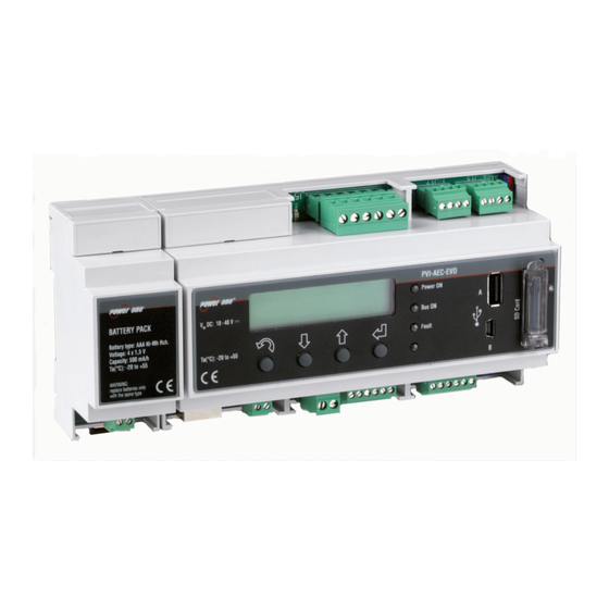
Monitoring System User interface and use of the display The system features a 2x16 character display,four buttons for navigating menus,and three LEDs to indicate device status. Using the display and the buttons on the front panel it is possible to perform the initial configuration of the system (check of parameter acquisition from inverter,analog input configuration,and configuration of LAN network parameters). -
Seite 7: Pin-Outs Of System Connectors
PVI-AEC-EVO / PVI-AEC-EVO LIGHT QUICK INSTALLATION GUIDE Pin-Out of System Connectors The diagram below shows the pin-out of the connectors which allow the system connection. RELAY 1) RELAY 1 - C RS485/1 RS485/2 2) RELAY 1 - N.O RELAY 2 - C 1) RTN 1) RTN RELAY 2 - N.O... -
Seite 8: Power Supply Connections And System Start Up
Monitoring System Power Supply Connections and System Start Up 1. Connect the power supply to the power supply network (100/240V 50/60Hz): the "Power" led on the power supply will light up steadily.Check that the output voltage of the power supply is 24Vdc.Disconnect the power supply from the power supply network. -
Seite 9: Date And Time Settings
PVI-AEC-EVO / PVI-AEC-EVO LIGHT QUICK INSTALLATION GUIDE Date and time settings 1. Enter the main menu as administrator (See par.'C’). 2. Access the menu 'SETTINGS' > 'DATALOGGER' and then select the 'SET DATE' sub-menu. This enables to set the correct date in the system. 3. - Seite 10 Monitoring System Note: For PVI-AEC-EVO LIGHT, the inverters must be set with addresses: 1, 2, 3, 4, 5. The configuration of address 1 corresponds to "AUTO" settings as inverter address. Note: When connecting multiple units (string inverter or/and 55kW conversion modules) it is necessary to wire the RS485 communication line according to the daisy-chain diagram (enter-exit).
- Seite 11 PVI-AEC-EVO / PVI-AEC-EVO LIGHT QUICK INSTALLATION GUIDE 9 - EN...
- Seite 12 Monitoring System 10 - EN...
-
Seite 13: Configuration Of The Analog Inputs
PVI-AEC-EVO / PVI-AEC-EVO LIGHT QUICK INSTALLATION GUIDE After carrying out these checks, start up first the monitoring system and then the inverters. The system automatically carries out a scan of the RS485 bus and automatically detects the available inverters.The presence of the inverters can be checked directly from the display. -
Seite 14: Upgrade Firmware
(Aln1/Aln2). The grounding of the signal to be measured (if different from the grounding of the power supply – within the Power-One sensor range only in the wind speed sensor PVI-AEC-WIND-COMPACT) must be connected to the Aln_RTN clamp. - Seite 15 20.0 DEGC CHANGE INPUT Note: In the following table it is reported a list of the sensor which are present in the catalogue “Power-one” . Fortheconnectionofthesesensors,pleasemakereferencetodiagrams shown in Appendix 1. SENSORS WITH ANALOG OUTPUTS COMPATIBLE WITH PVI-AEC-EVO (POWER-ONE CATALOGUE) MODELL...
-
Seite 16: System Configuration For Connection To The Lan Network (Ethernet Port)
Monitoring System System Configuration for connection to the LAN Network (Ethernet Port) The connection to the PC of PVI-AEC-EVO can be made through direct connection via Ethernet cable, or connecting both devices to a local network LAN (via router,hub or switch). In case of direct connection,it is enough to connect the two devices between them through a Ethernet cable and set the network parameters of PVI-AEC-EVO and of the PC to make sure they are compatible between them. - Seite 17 PVI-AEC-EVO / PVI-AEC-EVO LIGHT QUICK INSTALLATION GUIDE Select the option “Use the following IP address” and insert the network parameters (IP address, Subnet Mask, Gateway) compatible with the network parameters set in the PVI-AEC-EVO. DNS parameters fields can be let empty. Note: In case of direct connection between PVI-AEC-EVO and PC we suggest not to set “Gateway”...
-
Seite 18: Subnet Mask
Monitoring System CHANGETHE PVI-AEC-EVO NETWORK PARAMETERS :in order to change the PVI-AEC-EVO network parameters,please follow the procedure below: Power on the system and wait for the start up phase to complete (Ref.Par.'E’). Enter the main menu as administrator (Ref.Par.'C’). 3. Access the menu “SETTINGS”... -
Seite 19: Internal Webserver Access
PVI-AEC-EVO / PVI-AEC-EVO LIGHT QUICK INSTALLATION GUIDE Internal Webserver access In order to access to the Webserver pages of the system, after having done the connection of the system to the local network LAN or direct connection to the PC, open an internet browser (e.g. Internet Explorer) and type into the address bar the following address: http://<system IP address>... - Seite 20 To make the system fully functioning it is essential that the same system is constantly connected to the internet so that it is able to communicate with the Power-One server. This is essential to graphically shows the data on web pages as well as for sending alarm and/or report messages.It is essential that the LAN network in which the PVI-AEC-EVO is wired is such that it allows the connection to the IP address 63.236.63.180 to be reached through port 80, so that the...
- Seite 21 PVI-AEC-EVO / PVI-AEC-EVO LIGHT QUICK INSTALLATION GUIDE 19 - EN...
-
Seite 22: Mac Address Identification
Monitoring System MAC Address Identification During the process of association of PVI-AEC-EVO in Aurora Vision you will be prompted to enter the MAC address of the PVI-AEC-EVO present in the system. It is possible to obtain the MAC Address of your PVI-AEC-EVO observing the label on the right side of the product. The MAC Address is composed of 12 characters (separated by a colon) shown in red for example in the figure below. -
Seite 23: Firmware Updating
PVI-AEC-EVO / PVI-AEC-EVO LIGHT QUICK INSTALLATION GUIDE O. Firmware updating procedure via SD Card It is possible to upgrade the firmware of the PVI-AEC-EVO either locally using the SD Card, or remotely using the web portal AuroraVision. Note: The firmware update via SD card should be carried out only if it is not possible to update the firmware viatheAuroraVisionwebportal Note: For details on the procedure for the firmware updating through the web portal Aurora Vision, refer... - Seite 24 Monitoring System 16. Follow the path “SETTINGS>UPGRADEFIRMWARE>UPGRADEDISPLAY” press ENTER to confirm;wait the completing of upgrade (few minutes).The upgrading process will be completed when the message “Upgrade Success” will be displayed. 17. Follow the path “SETTINGS > UPGRADE CONFIG” press ENTER to confirm; wait the completing of upgrade (few minutes).The upgrading process will be completed when the message “UPGRADE CONFIG”...
- Seite 25 PVI-AEC-EVO / PVI-AEC-EVO LIGHT GUIDA DI INSTALLAZIONE RAPIDA INDICE Descrizione del prodotto Contenuto della confezione Interfaccia Utente ed utilizzo del display Piedinatura dei connettori del sistema Collegamento dell’alimentazione del sistema Impostazione di data ed ora Collegamento della linea RS485 e verifica dell’acquisizione degli inverter Configurazione degli ingressi analogici ConfigurazionedelsistemaperlaconnessioneinreteLAN(portaEthernet) Accesso al Webserver interno...
-
Seite 26: Descrizione Del Prodotto
I sistemi PVI-AEC-EVO e PVI-AEC-EVO LIGHT sono sistemi di monitoraggio e controllo degli impianti fotovoltaici realizzati con prodotti Power-One. Nel seguito si farà riferimento al "sistema" intendendo entrambe le versioni di prodotto,mentre verrà specificato il modello nel caso in cui le loro caratteristiche siano differenti. -
Seite 27: Guida Di Installazione Rapida
Controllare inoltre che non vi siano danneggiamenti alla confezione, al dispositivo e agli accessori in corredo. In caso di non conformità si consiglia di presentare reclamo presso la ditta di trasporti e di comunicare tempestivamente al servizio di assistenza tecnica oppure al customer service di Power-One ladifformitàriscontrata. -
Seite 28: Utilizzo Dei Pulsanti
Monitoring System Interfaccia Utente ed utilizzo del display Il sistema dispone di un display 2x16 caratteri, quattro pulsanti per la navigazione nei menu e tre LED che indicano lo stato del dispositivo. Attraverso l’uso del display e dei pulsanti posti sul pannello frontale è possibile effettuare la configurazione iniziale del sistema (verifica dell'acquisizione dei parametri da inverter, configurazione degli ingressi analogici, configurazione dei parametri di rete LAN). - Seite 29 PVI-AEC-EVO / PVI-AEC-EVO LIGHT GUIDA DI INSTALLAZIONE RAPIDA Piedinatura dei connettori del sistema Lo schema di seguito riporta la piedinatura dei connettori che permettono la connessione del sistema. RELAY 1) RELAY 1 - C RS485/1 RS485/2 2) RELAY 1 - N.O RELAY 2 - C 1) RTN 1) RTN...
- Seite 30 Monitoring System Collegamenti di alimentazione del sistema 1. Collegare l'alimentatore alla rete di alimentazione (100/240V - 50/60Hz):il led“Power”dell'alimentatore si accenderà stabilmente. Verificare che la tensione di uscita dell'alimentatore sia 24Vdc. Scollegare l'alimentatore dalla rete di alimentazione. 2. Collegare l'uscita dell'alimentatore alla morsettiera di alimentazione del PVI-AEC-EVO (rispettando la polarità) utilizzando il cablaggio fornito a corredo.
-
Seite 31: Impostazione Di Data Ed Ora
PVI-AEC-EVO / PVI-AEC-EVO LIGHT GUIDA DI INSTALLAZIONE RAPIDA Impostazione di data ed ora 1. Accedere al menu principale come amministratore (Rif.Par.“C”). 2. Accedere al menu “SETTINGS” > “DATALOGGER” quindi selezionare il sottomenu “SET DATE”. Sarà possibile impostare la data corretta nel sistema. 3. - Seite 32 Monitoring System Nota: Nel caso della versione PVI-AEC-EVO LIGHT gli indirizzi RS485 disponibili per gli inverter sono: 1, 2, 3, 4, 5 (negli inverter l’indirizzo 1 corrisponde all’impostazione“AUTO”). Nota: In caso di collegamento di più unità (inverter di stringa o/e moduli di conversione da 55kW) è necessario cablare la linea di comunicazione RS485 in accordo allo schema daisy-chain (entra-esci).
- Seite 33 PVI-AEC-EVO / PVI-AEC-EVO LIGHT GUIDA DI INSTALLAZIONE RAPIDA 9 - IT...
- Seite 34 Monitoring System 10 - IT...
- Seite 35 PVI-AEC-EVO / PVI-AEC-EVO LIGHT GUIDA DI INSTALLAZIONE RAPIDA Dopo aver effettuato queste verifiche, mettere in servizio prima il sistema di monitoraggio e successivamente gli inverter. Il sistema effettua automaticamente la scansione del bus RS485 e quindi rileva in automatico gli inverter presenti.
-
Seite 36: Upgrade Firmware
Monitoring System La misura viene effettuata tra PT_SENSE e PT_RTN; l'elemento di misura deve essere cablato tra questi due segnali. Il sensore PT100/PT1000 viene automaticamente riconoscuito dal sistema e quindi acquisito senza necessità di ulteriori impostazioni. In merito al collegamento dei sensori con range di uscita 0...10Vdc,questi devono essere alimentati e l'alimentazione può essere prelevata direttamente dall'alimentazione del sistema;... - Seite 37 20.0 DEGC CHANGE INPUT Nota: Nella tabella di seguito si riporta la lista dei sensori presenti nel sistema ed offerti a catalogo Power- One. PerlaconnessioneditalisensorifareriferimentoaglischemipresentiinAppendice1. SENSORI CON USCITA ANALOGICA COMPATIBILI CON PVI-AEC-EVO (A CATALOGO POWER-ONE) MODELLO TIPOLOGIA IDENTIFICATIVO RANGE DISPLAY OPERATIVO Sensore Irraggiamento (W/m -->...
- Seite 38 Monitoring System Configurazione del sistema per la connessione in rete LAN (porta Ethernet) La connessione del PVI-AEC-EVO al PC può essere effettuata attraverso connessione diretta tramite cavo ethernet, oppure connettendo entrambi i dispositivi ad una rete locale LAN (attraverso router,hub o switch). In caso di connessione diretta è...
- Seite 39 PVI-AEC-EVO / PVI-AEC-EVO LIGHT GUIDA DI INSTALLAZIONE RAPIDA Selezionare l’opzione “Utilizza il seguente indirizzo IP” ed inserire i parametri di rete (Indirizzo IP,Subnet Mask,Gateway) compatibili con i parametri di rete configurati nel PVI-AEC-EVO. I campi relativi al DNS possono essere lasciati vuoti. Nota: In caso di connessione diretta tra PVI-AEC-EVO e PC si consiglia di non configurare il parametro “Gateway”.
-
Seite 40: Subnet Mask
Monitoring System MODIFICA DEI PARAMETRI DI RETE DEL PVI-AEC-EVO Per modificare i parametri di rete del PVI-AEC-EVO seguire la procedura sottostante: 1. Alimentare il sistema ed attendere il completamento della fase di avvio (Rif.Par.”E”). 2. Accedere al menu principale come amministratore (Rif.Par.“C”) 3. - Seite 41 PVI-AEC-EVO / PVI-AEC-EVO LIGHT GUIDA DI INSTALLAZIONE RAPIDA Accesso al Webserver interno Per accedere alle pagine di Webserver del sistema dopo aver effettuato la connessione del sistema alla rete locale LAN oppure diretta al PC,aprire un browser internet (es.Internet Explorer) e digitare nella barra degli indirizzi: http://<indirizzo IP del sistema>...
- Seite 42 Nota: Per rendere completamente funzionante il sistema è indispensabile che il sistema stesso sia continuativamente connesso ad internet in modo da poter dialogare con il server di Power-One per le operazioni di visualizzazione grafica dei dati su pagine web oltre che per l'invio di messaggi di allarme e/o di report.
- Seite 43 PVI-AEC-EVO / PVI-AEC-EVO LIGHT GUIDA DI INSTALLAZIONE RAPIDA 19 - IT...
-
Seite 44: Mac Address
Monitoring System Identificazione del MAC Address Durante il processo di associazione dei PVI-AEC-EVO in AuroraVision verrà richiesto di inserire i MAC Address dei PVI-AEC- EVO presenti in impianto. E’possibile ricavare il MAC Address del proprio PVI-AEC-EVO osservando l’etichetta presente sul lato destro del prodotto.Il MAC Address è... -
Seite 45: Aggiornamento Firmware
PVI-AEC-EVO / PVI-AEC-EVO LIGHT GUIDA DI INSTALLAZIONE RAPIDA N. Aggiornamento Firmware E’possibile eseguire l’aggiornamento del Firmware del PVI-AEC-EVO sia localmente utilizzando la SD Card,sia da remoto utilizzando il portale web AuroraVision. Nota: L’aggiornamento del firmware attraverso SD Card deve essere effettuato solo nel caso in cui non sia possibile effettuare l’aggiornamento del firmware attraverso il portale web Aurora Vision Nota: Per dettagli sulla procedura di aggiornamento del firmware attraverso portale web Aurora Vision,... - Seite 46 Monitoring System 15. Accedere al menu “ SETTINGS” > “UPGRADE FIRMWARE” > “UPGRADE ADC” > Confirm per procedere; attendere il completamento dell'aggiornamento. Il processo di aggiornamento sarà completato quando a display sarà visualizzato il messaggio “UpgradeSuccess”. 16. Accedere al menu“ SETTINGS”...
- Seite 47 PVI-AEC-EVO / PVI-AEC-EVO LIGHT SCHNELLINSTALLATIONSANLEITUNG INHALTSVERZEICHNIS Beschreibung des Produkts Packungsinhalt Benutzerschnittstelle und Verwendung des Displays Pinbelegung der Systemstecker Versorgungsanschlüsse und Einschaltung des Systems Einstellung von Datum und Uhrzeit Anschlüsse der Leitung RS485 und Überprüfung der Erfassung der Wechselrichter Konfiguration der Analogeingänge Konfiguration des Systems für den Anschluss an das LAN-Netzwerk (Ethernet-Port) Zugriff zum Internen Webserver Identifizierung der MAC-Adresse...
-
Seite 48: Beschreibung Des Produkts
Versionen gemeint wenn nicht spezifisch auf eine bestimmte Variante hingewiesen wird. Mit dem Produkt können die Parameter von Wechselrichtern und Stringcombs (je nach Aufbau der Überwachung der zentralisierten Wechselrichter) über die Leitung RS485 mit dem proprietären Protokoll von Power-One erfasst werden. -
Seite 49: Packungsinhalt
Hinweis:Bitte überprüfen den Inhalt der Packung gemäss obiger Liste. Bitte überprüfen Sie ob die Schachtel der Inhalt keine Beschädigung aufweist. Im Falle von Beschädigung wenden Sie sich an die Transportfirma und durch zeitgerechter Mitteilung technischen Serviceunterstuetzung oder den Kundendienst Power-One in Anbetracht der Stoerungstypologie. 3 - DE... -
Seite 50: Benutzerschnittstelle Und Verwendung Des Displays
Monitoring System Benutzerschnittstelle und Verwendung des Displays Das System verfügt über ein Display mit 2x16 Zeichen, vier Tasten zum Navigieren in den Menüs und drei LEDs zur Statusanzeige des Geräts. Die Anfangskonfiguration des Systems (Überprüfung der Erfassung der Parameter von Wechselrichtern, Konfiguration der Analogeingänge, Konfiguration der Parameter des LAN-Netzwerks) kann über das Display und die Tasten an der Frontabdeckung vorgenommen werden. -
Seite 51: Pinbelegung Der Systemstecker
PVI-AEC-EVO / PVI-AEC-EVO LIGHT SCHNELLINSTALLATIONSANLEITUNG Pinbelegung der Systemstecker Im nachfolgend aufgeführten Schema werden die Pin-out der Stecker gezeigt, mit denen das System angeschlossen wird. RELAY 1) RELAY 1 - C RS485/1 RS485/2 2) RELAY 1 - N.O RELAY 2 - C 1) RTN 1) RTN RELAY 2 - N.O... -
Seite 52: Versorgungsanschlüsse Und Einschaltung Des Systems
Monitoring System Versorgungsanschlüsse und Einschaltung des Systems 1. Das Stromversorgungsgerät an das Versorgungsnetz (100/240V 50/60Hz) anschließen: die LED “Power” des Stromversorgungsgeräts leuchtet dauerhaft auf. Überprüfen, ob die Ausgangsspannung des Stromversorgungsgeräts 24Vdc beträgt. Das Stromversorgungsgerät vom Versorgungsnetz abnehmen. 2. Den Ausgang des Stromversorgungsgeräts an das Versorgungs-Klemmenbrett des PVI-AEC-EVO polaritätsrichtig unter Verwendung der im Lieferumfang enthaltenen Verkabelung anschließen. -
Seite 53: Einstellung Von Datum Und Uhrzeit
PVI-AEC-EVO / PVI-AEC-EVO LIGHT SCHNELLINSTALLATIONSANLEITUNG Einstellung von Datum und Uhrzeit 1. Das Hauptmenü als Administrator (siehe Abschn.“C”) öffnen. 2. Das Menü “SETTINGS” > “DATALOGGER” öffnen und das Untermenü “SET DATE” anwählen. Das korrekte Datum des Systems kann eingestellt werden. 3. In das Menü “DATALOGGER”... - Seite 54 Monitoring System Hinweis:Beim PVI-AEC-EVO LIGHT müssen die Adressen 1,2,3,4 und 5 vergeben werden. Die Adresse 1 entsprichtderEinstellung'AUTO'amWechselrichter. Hinweis:Für den Anschluss mehrerer Einheiten (String-Wechselrichter oder/und Wandlungsmodule mit 55kW) muss die RS485-Übertragungsleitung in Übereinstimmung mit dem Daisy-Chain-Schema ("hinein-heraus")verkabeltwerden. Der letzte Wechselrichter der Daisy Chain-Kette wird beendet, indem die Abschlusswiderstand der Ω...
- Seite 55 PVI-AEC-EVO / PVI-AEC-EVO LIGHT SCHNELLINSTALLATIONSANLEITUNG 9 - DE...
- Seite 56 Monitoring System 10 - DE...
-
Seite 57: Konfiguration Der Analogeingänge
PVI-AEC-EVO / PVI-AEC-EVO LIGHT SCHNELLINSTALLATIONSANLEITUNG Nach diesen Überprüfungen wird zuerst das Überwachungssystem und danach werden die Wechselrichter in Betrieb genommen. Das System führt automatisch die Abtastung des Bus RS485 aus und erfasst damit automatisch die vorhandenen Wechselrichter. Die Überprüfung des Vorhandenseins der Wechselrichter kann direkt über das Display vorgenommen werden. -
Seite 58: Upgrade Firmware
Größe eines der beiden verfügbaren Analogeingänge erforderlich (AIn1/AIn2). Die Masse des Messsignals (soweit diese von der Masse der Versorgung abweicht – dies ist bei den Sensoren Power-One nur beim Sensor für die Windgeschwindigkeit PVI-AEC-WIND-COMPACT der Fall) muss an die Klemme AIn_RTN angeschlossen werden. - Seite 59 SETTINGS ENTER ENTER >T1000-INTEGR 20.0 DEGC CHANGE INPUT Hinweis: In der folgenden Tabelle ist eine Liste von Sensoren ausgefuehrt welche vom Katalog POWER-ONE angebotenwrden.FuerdieVebindungenderSensorengehenSieaufdenAppendix1. SENSOREN MIT ANALOGAUSGANG,DIE MIT DEM PVI-AEC-EVO KOMPATIBEL SIND (KATALOG POWER-ONE) MODELL KENNUNG EINSATZBEREICH DISPLAY SensorSonneneinstrahlung(W/m -->V)
-
Seite 60: Konfiguration Des Systems Für Den Anschluss An Das Lan-Netzwerk (Ethernet-Port)
Monitoring System Konfiguration des Systems für den Anschluss an das LAN-Netzwerk (Ethernet-Port) DieVerbindung des PVI-AEC-EVO am PC kann direkt ueber eine Ethernetkabelverbindung,oder beide Einheiten am Netz verbinden – lokales LAN (ueber router,huboswitch). Bei einer direktenVerbindung reicht es aus die beiden Einheiten durch ein Ethernetkabel und die Netzparameter des PVI- AEC-EVO und den PC un sicher zu stellen dass diese miteinander kompatibel sind. - Seite 61 PVI-AEC-EVO / PVI-AEC-EVO LIGHT SCHNELLINSTALLATIONSANLEITUNG Selektieren Option „Benutzen Sie die folgende IP Adresse“ und einfügen Netzparameter (Adresse IP , Subnet Mask, Gateway) kompatibel mit den Netzparametern konfiguriert in PVI-AEC-EVO. Die Felder fuer DNS koennen leer bleiben. Hinweis: Im Fall einer direkten Verbindung zwischen PVI-AEC-EVO und PC schlagen wir vor den Parameter „Gateway“nichtzukonfigurieren.
-
Seite 62: Subnet Mask
Monitoring System MODIFIKATION DER NETZPARAMETER VON PVI-AEC-EVO: Um die Netzparameter des PVI-AEC-EVO zu modifizieren gehen Sie wie folgt vor: 1. Das System versorgen und abwarten,bis die Startphase abgeschlossen ist (siehe Abschn.“E”). 2. Das Hauptmenü als Administrator (siehe Abschn.“C”) öffnen. 3. Das Menü “SETTINGS”... -
Seite 63: Zugang Zum Internen Webserver
PVI-AEC-EVO / PVI-AEC-EVO LIGHT SCHNELLINSTALLATIONSANLEITUNG Zugang zum Internen Webserver Um auf die Seiten des Webservers zugreifen zu koennen nach einer Verbindung des Systems an einem lokalen LAN Netz oder direkt am PC, wird ein Internet-Browser (bspw.Internet Explorer) geöffnet und in die Adressenleiste wird folgendes http://<IP-Adresse des Systems>... - Seite 64 Hinweis: Damit das System uneingeschränkt betrieben werden kann, muss es dauerhaft mit dem Internet verbunden sein, damit es mit dem Server von Power-One kommunizieren kann. Dies betrifft die graphische Anzeige der Daten in den Webseiten sowie die Versendung von Alarm- und/oder Berichtsmeldungen.
- Seite 65 PVI-AEC-EVO / PVI-AEC-EVO LIGHT SCHNELLINSTALLATIONSANLEITUNG 19 - DE...
-
Seite 66: Identifizierung Der Mac-Adresse
Monitoring System Identifizierung der MAC-Adresse Während der Prozessvernuepfung von PVI-AEC-EVO in Aurora Vision wird man aufgefordert, die MAC-Adresse des PVI- AEC-EVO im System einzugeben. MAC-Adresse kann der Etikette auf der rechten Seite des PVI-AEC-EVO entnommen werden. Die MAC-Adresse besteht aus 12 Zeichen (getrennt durch einen Doppelpunkt) rot in der Abbildung unten welches als Beispiel angezeigt wird. -
Seite 67: Firmware Update
PVI-AEC-EVO / PVI-AEC-EVO LIGHT SCHNELLINSTALLATIONSANLEITUNG irmware Update Es ist moeglich das Update der Firmware des PVI-AEC-EVO sowie lokal ueber die SD Karte - sowie ueber Remote unter Benutzung desWeb Portals AuroraVision durchzufuehren. Hinweis: Die Firmware-Aktualisierung über SD Card muss nur dann durchgeführt werden,wenn die Firmware- AktualisierungüberWebPortalsAuroraVisionnichtmöglichist. - Seite 68 Monitoring System 16. Über “EINSTELLUNGEN” > “UPGRADE FIRMWARE” > “UPGRADE DISPLAY” kann der Upgrade des Display gestartet werden (Enter um zu bestätigen) Dieser Vorgang kann wiederum mehrere Minuten dauern. Ist der Vorgang abgeschlossen wird dies durch die Meldung “Upgradeerfolgreich“ am Display angezeigt. 17.
- Seite 69 PVI-AEC-EVO / PVI-AEC-EVO LIGHT GUIDE D'INSTALLATION RAPIDE TABLE DES MATIÈRES Description du produit Contenu de l'emballage Interface Utilisateur et utilisation de l'afficheur Brochage des connecteurs du système Branchements d'alimentation et de mise en marche du système Réglage de la date et de l'heure Branchements de la ligne RS485 et vérification de l'acquisition des onduleurs Configuration des entrées analogiques Configuration du système pour le branchement en réseau LAN (porte Ethernet)
-
Seite 70: Description Du Produit
Le PVI-AEC-EVO est un système de surveillance et de contrôle des installations photovoltaïques réalisées avec les produits Power-One Aurora. Suivant on fera réfeérence au système en entendant les deux versions du produit, par contre on spécifiera le modèle dans le cas lequel les leur caractéristiques soient différents. -
Seite 71: Contenu De L'emballage
PVI-AEC-EVO / PVI-AEC-EVO LIGHT GUIDE D'INSTALLATION RAPIDE Contenu de l'emballage AURORA PVI-AEC-EVO / PVI-AEC-EVO LIGHT Alimentation 100-240Vac 50-60Hz / 24Vdc Câble de connexion de l'alimentation Guide d'installation rapide Carte SD (assemblé) Blocs Terminaux homologues E/S (assemblé) Borniers RS485 homologues (assemblé) Borniers Relais homologues (assemblé) -
Seite 72: Interface Utilisateur Et Utilisation De L'afficheur
Monitoring System Interface Utilisateur et utilisation de l'afficheur Le système dispose d'un afficheur 2x16 caractères, de quatre boutons pour le défilement à l'intérieur des menus et de trois DELs indiquant l'état du dispositif. En utilisant l'afficheur et les boutons situés sur le panneau avant, il est possible d'effectuer le réglage initial du système (vérification de l'acquisition des paramètres d'onduleurs, réglage des entrées analogiques, configuration des paramètres de réseau LAN). -
Seite 73: Brochage Des Connecteurs Du Système
PVI-AEC-EVO / PVI-AEC-EVO LIGHT GUIDE D'INSTALLATION RAPIDE Brochage des connecteurs du système Le schéma ci-dessous indique le pin-out des connecteurs permettant la connexion du système. RELAY 1) RELAY 1 - C RS485/1 RS485/2 2) RELAY 1 - N.O RELAY 2 - C 1) RTN 1) RTN RELAY 2 - N.O... -
Seite 74: Branchements D'alimentation Et De Mise En Marche Du Système
Monitoring System Branchements d'alimentation et de mise en marche du système 1. Brancher le bloc d'alimentation sur le réseau d'alimentation électrique (100/240V 50/60Hz) : la DEL « Power » du bloc d'alimentation s'allumera de façon fixe.Vérifier que la tension de sortie du bloc d'alimentation soit de 24Vdc. -
Seite 75: Réglage De La Date Et De L'heure
PVI-AEC-EVO / PVI-AEC-EVO LIGHT GUIDE D'INSTALLATION RAPIDE Réglage de la date et de l'heure 1. Accéder au menu principale en tant qu'administrateur (cf. Paragraphe « C »). 2. Accéder au menu « SETTINGS » > « DATALOGGER » puis sélectionner le sous-menu «... - Seite 76 Monitoring System Remarque: Pour le PVI-AEC-EVO LIGHT,les onduleurs doivent être configurés avec les adresses: 1,2,3,4,5. L'adresse 1 correspondant au paramétrages «AUTO» de l'onduleur. Remarque: En cas de branchement de plusieurs unités (onduleurs de chaîne et/ou modules de conversion de 55kW) il faut câbler la ligne de communication RS485 conformément au schéma daisy-chain (entrée-sortie).
- Seite 77 PVI-AEC-EVO / PVI-AEC-EVO LIGHT GUIDE D'INSTALLATION RAPIDE 9 - FR...
- Seite 78 Monitoring System 10 - FR...
-
Seite 79: Configuration Des Entrées Analogiques
PVI-AEC-EVO / PVI-AEC-EVO LIGHT GUIDE D'INSTALLATION RAPIDE Après avoir effectué ces vérifications, mettre en marche d'abord le système de surveillance et ensuite les onduleurs. Le système effectue alors automatiquement l'analyse du bus RS485 et détecte donc automatiquement les onduleurs présents.Pour vérifier la présence des onduleurs,il est possible de procéder directement depuis l'afficheur. 1. - Seite 80 (AIn1/AIn2). La masse du signal de mesure (si jamais celle-ci était différente de la masse de l'alimentation – en ce qui concerne la gamme des capteurs Power-One uniquement pour le capteur de vitesse de vent PVI-AEC-WIND-COMPACT) doit être branchée sur la borne AIn_RTN. Après avoir effectué les branchements, il faudra régler le capteur sur le système de façon à...
- Seite 81 >CURRENT VALUE DIGITAL VALUE SETTINGS ENTER ENTER >T1000-INTEGR 20.0 DEGC CHANGE INPUT Remarque: Dansletableausuivantilyaunelistedecapteursquisontpresentsdanslesystèmeetilssetrouventaussi danslecataloguePower-One.Pourlaconnexiondecescapteurs,seréférerauxschémassituésàl'Annexe1. CAPTEURS AVEC SORTIE ANALOGIQUE COMPATIBLES AVEC PVI-AEC-EVO (CATALOGUE POWER-ONE) MODELE TYPOLOGIE IDENTIFIANT GAMMEDE AFFICHEUR FONCTIONNEMENT Capteur Rayonnement (W/m --> V) PVI-AEC-IRR 0-1200 W/m PVI-AEC-IRR-T Capteur Rayonnement avec capt.Temp.
-
Seite 82: Configuration Du Système Pour Le Branchement En Réseau Lan (Porte Ethernet)
Monitoring System Configuration du système pour le branchement en réseau LAN (porte Ethernet) La connexion du PVI-AEC-EVO à l'ordinateur peut être effectué à travers une connexion directe par le câble Ethernet,ou en joignant les deux dispositives à un réseau local LAN (par router,hub ou switch). En cas de connexion directe, il est suffisant de joindre les deux dispositives par un câble ethernet et configurer les paramètres du réseau du PVI-AEC-EVO et de l'ordinateur,de manière que ils soient compatibles entre eux. - Seite 83 PVI-AEC-EVO / PVI-AEC-EVO LIGHT GUIDE D'INSTALLATION RAPIDE Sélectionner l'option "Utilise l'adresse IP suivant" et insérer le paramètres du réseau (Adresse IP,Subnet Mask,Gateway) compatibles avec les paramètres du réresau configurés dans le PVI-AEC-EVO. Les champs relatives au DNS peuvent être laissés vides. Remarque: En cas de connexion directe entre PVI-AEC-EVO et ordinateur il est conseillé...
- Seite 84 Monitoring System MODIFIER LES PARAM TRES DU R RESEAU DU PVI-AEC-EVO È É Pour modifier les paramètres du réseau du PVI-AEC-EVO il faut suivre la procédure suivante: 1. Mettre sous tension le système et attendre que la phase de démarrage ait terminé (cf.Paragraphe «...
-
Seite 85: Accès Au Webserver Interne
PVI-AEC-EVO / PVI-AEC-EVO LIGHT GUIDE D'INSTALLATION RAPIDE Accès au Webserver Interne Pour acceder aux pages du Webserver du système après avoir effectué la connexion du système au réseau local LAN ou direct à l'ordinateur ouvrir un browser internet (par ex.Internet Explorer) et taper dans la barre d'adresse : http://<adresse IP du système>... - Seite 86 Remarque: Pour que le système fonctionne correctement, il est indispensable que celui-ci soit continuellement connecté à Internet de façon à pouvoir interagir avec le serveur de Power-One pour les opérations d'affichage graphique des données sur les pages internet ainsi que pour l'envoi de messages d'alarme et/ou de rapports.
- Seite 87 PVI-AEC-EVO / PVI-AEC-EVO LIGHT GUIDE D'INSTALLATION RAPIDE 19 - FR...
-
Seite 88: Identification De L'adresse Mac
Monitoring System Identification de l'adresse MAC Pendant le processus d'association des PVI-AEC-EVO à Aurora Vision vous serez invité à entrer l'adresse MAC du PVI-AEC- EVO présent dans le système. Il est possible d'obtenir l'adresse MAC de votre PVI-AEC-EVO en observant l'étiquette sur le côté droit du produit. L'adresse MAC est composé... -
Seite 89: Mise À Jour Du Firmware
PVI-AEC-EVO / PVI-AEC-EVO LIGHT GUIDE D'INSTALLATION RAPIDE Mise à jour du Firmware Il est possible de mettre à jour le firmware du PVI-AEC-EVO, soit localement à l'aide de la carte SD, ou à distance via le portail web AuroraVision. Remarque: Lamiseàjourdumicrologicielàl'aided'unecarteSDdoitêtreeffectuée uniquementdanslecasoù... - Seite 90 Monitoring System 16. Suivre le chemin suivant: « UPGRADE FIRMWARE » « UPGRADE DISPLAY » > presser ENTER pour confirmer;attendre la fin de la mise à jour (quelques minutes).La mise à jour sera finie lorsque le message «UpgradeSuccess » s'affichera. 17.
- Seite 91 PVI-AEC-EVO / PVI-AEC-EVO LIGHT QUICK INSTALLATION GUIDE Appendix 1. Wiring Diagrams for compatible sensors Wiring Diagrams for the Sensors PVI-AEC-T100-ADH 1 - APPENDIX...
- Seite 92 Monitoring System Wiring Diagrams for the Sensors PVI-AEC-T1000-BOX 2 - APPENDIX...
- Seite 93 PVI-AEC-EVO / PVI-AEC-EVO LIGHT QUICK INSTALLATION GUIDE Wiring Diagrams for the Sensor PVI-AEC-T1000-INTEGR 3 - APPENDIX...
- Seite 94 Monitoring System Wiring Diagrams for the Sensors PVI-AEC-IRR / PVI-AEC-RAD-13TC 4 - APPENDIX...
- Seite 95 PVI-AEC-EVO / PVI-AEC-EVO LIGHT QUICK INSTALLATION GUIDE Wiring Diagrams for the Sensors PVI-AEC-IRR-T / PVI-AEC-RAD-13-TC-T 5 - APPENDIX...
- Seite 96 Monitoring System Wiring Diagrams for the Sensors PVI-AEC-PYR-1300 6 - APPENDIX...
- Seite 97 PVI-AEC-EVO / PVI-AEC-EVO LIGHT QUICK INSTALLATION GUIDE Note: The internal heater (+Vcc_Heat and -Vcc_Heat) must be supplied by supplementary power supply. For more details about internal heater refer to PVI-AEC-EVO User Manual. Wiring Diagrams for the Sensor PVI-AEC-WIND-COMPACT 7 - APPENDIX...
- Seite 98 Monitoring System Note: The internal heater (+Vcc_Heat and -Vcc_Heat) must be supplied by supplementary power supply. For more details about internal heater refer to PVI-AEC-EVO User Manual. Wiring Diagrams for the Sensor PVI-AEC-WIND-DIR 8 - APPENDIX...
- Seite 99 PVI-AEC-EVO / PVI-AEC-EVO LIGHT QUICK INSTALLATION GUIDE 2. RS485 Cable Specification SINGLE TWISTED PAIR RS485 CABLE SPECIFICATION Type of Cable RS485 EIA Application Cable Structure 1 twisted pair + 1 single conductor, shielded 22 - 24 Ω Charateristic Impedance Working Frequency 1 kHz / 1 MHz Capacitance <50pF / m...
-
Seite 100: Change Password
Monitoring System 3. Display flow-charts MAIN PAGE INFORMATION SETTINGS PRODUCT DATALOGGER NETWORK SET DATE FIRMWARE AVR SET TIME FIRMWARE BOOTLOADER IO SETTINGS FIRMWARE ADC_IO ANALOG INPUT 1 FIRMWARE DISPLAY ANALOG INPUT 2 NETWORK DIN 1-4 CURRENT IP ADDRESS DIN 6/IN_CONT 1 CURRENT SUBNET DIN 5/IN_CONT 2 CURRENT GATEWAY... - Seite 101 PVI-AEC-EVO / PVI-AEC-EVO LIGHT QUICK INSTALLATION GUIDE 4. Compliance Requirements 11 - APPENDIX...
- Seite 102 Monitoring System 12 - APPENDIX...
- Seite 103 PVI-AEC-EVO / PVI-AEC-EVO LIGHT QUICK INSTALLATION GUIDE 13 - APPENDIX...
- Seite 104 Monitoring System 14 - APPENDIX...
- Seite 105 PVI-AEC-EVO / PVI-AEC-EVO LIGHT QUICK INSTALLATION GUIDE 15 - APPENDIX...
- Seite 106 Increase the separation between the equipment and receiver. Ÿ Connect the equipment into an outlet on a circuit different from that to which the receiver is connected. Ÿ Consult the dealer or an experienced radio/TV technician for help. Power-One PVI-AEC-EVO Power-One PVI-AEC-EVO LIGHT 16 - APPENDIX...