
Verwandte Anleitungen für VEGA VEGAVIB S 61


Inhaltszusammenfassung für VEGA VEGAVIB S 61
-
Seite 1: Betriebsanleitung
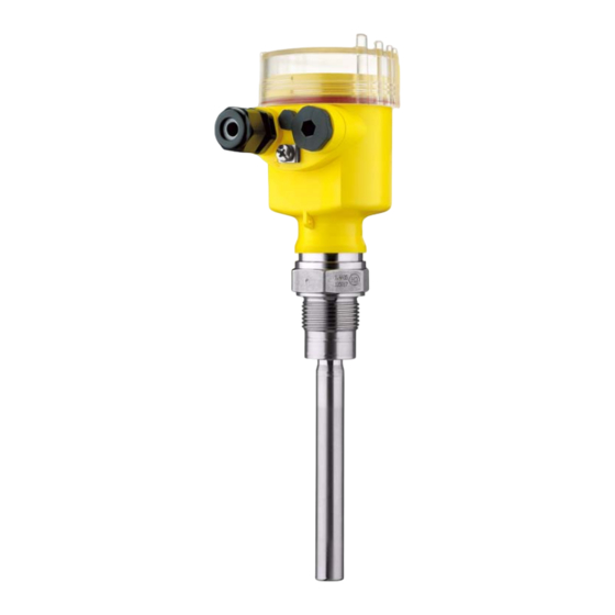
Betriebsanleitung Operating instructions manual Manuel de mise en service Instrucción de servicio VEGAVIB S 61... -
Seite 2: Inhaltsverzeichnis
Sicherheitshinweise für Ex- Bereiche Produktbeschreibung Aufbau Arbeitsweise Lagerung und Transport Montieren Allgemeine Hinweise Montagehinweise An die Spannungsversorgung anschließen Anschluss vorbereiten Anschlussschritte Anschlussplan In Betrieb nehmen Allgemein Bedienelemente Funktionstabelle Instandhalten Wartung 24 Stunden Service-Hotline Das Gerät reparieren Ausbauen VEGAVIB S 61... -
Seite 3: Zu Ihrer Sicherheit
Stand der jeweils geltenden Regel- werke festzustellen und neue Vorschriften zu 1.2 Bestimmungsgemäße Verwendung beachten. Der VEGAVIB S 61 ist ein Sensor zur Grenz- standerfassung. 1.5 CE-Konformität Detaillierte Angaben zum Einsatzbereich finden Sie Der VEGAVIB S 61 ist CE-konform zum EMVG (89/ im Kapitel "Produktbeschreibung". -
Seite 4: Arbeitsweise
Abb. 1: Maßnahmen gegen das Eindringen von Feuchtigkeit zustand an, d. h. das Relais wird stromlos (sicherer Zustand). Transport Halten Sie den VEGAVIB S 61 nicht am Schwing- Funktionsprinzip element. Insbesondere bei Flansch- oder Rohr- Der Schwingstab wird piezoelektrisch angetrieben versionen kann der Sensor durch das Gerätege-... -
Seite 5: Montagehinweise
An die Spannungsversorgung anschließen 3.2 Montagehinweise nen Installationsvorschriften. Verbinden Sie den VEGAVIB S 61 grundsätzlich mit der Behältererde Stutzen (PA) bzw. bei Kunststoffbehältern mit dem Das Schwingelement sollte möglichst frei in den nächstgelegenen Erdpotenzial. Seitlich am Ge- Behälter ragen. rätegehäuse befindet sich dazu eine Erdungs- klemme zwischen den Kabelverschraubungen. -
Seite 6: Anschlussplan
Relais 1 Relais 2 Kontrollleuchte Dichteanpassung (DIL-Schalter) Betriebsartenumschaltung min/max (DIL-Schalter) Wir empfehlen den VEGAVIB S 61 so anzuschlie- ßen, dass der Schaltstromkreis bei Grenzstand- meldung, Leitungsbruch oder Störung geöffnet ist (sicherer Zustand). Die Relais sind immer im Ruhezustand dargestellt. VEGAVIB S 61... -
Seite 7: In Betrieb Nehmen
0,1 und 0,3 g/cm³ haben. Trockenlauf- oder schutz Transistor Der Schalter des VEGAVIB S 61 steht ab Werk auf sperrt dem großen Gewichtssymbol (> 0,3 g/cm³). Bei Ausfall der Relais strom- besonders leichten Schüttgütern stellen Sie den beliebig... -
Seite 8: Instandhalten
Instandhalten 6 Instandhalten 7 Ausbauen 6.1 Wartung 7.1 Ausbauschritte Der VEGAVIB S 61 bedarf bei bestimmungsge- Warnung: mäßer Verwendung keiner besonderen Wartung. Achten Sie vor dem Ausbauen auf gefähr- liche Prozessbedingungen wie z. B. Druck 6.2 24 Stunden Service-Hotline im Behälter, hohe Temperaturen, aggres- sive oder toxische Füllgüter etc. -
Seite 9: Anhang
55 V DC Schaltstrom max. 400 mA Sperrstrom < 100 µA Betriebsarten (umschaltbar) min./max. Schaltverzögerung ein: ca. 0,5 sek. / aus: ca. 1 sek. Umgebungsbedingungen Umgebungstemperatur -40 … +80 °C Lager- und Transporttempe- -40 … +80 °C ratur VEGAVIB S 61... - Seite 10 Leistungsaufnahme 1 … 8 VA (AC), ca. 1,3 W (DC) Transistorausgang Versorgungsspannung 10 … 55 V DC Leistungsaufnahme max. 0,5 W Elektrische Schutzmaßnahmen Schutzart IP 66/IP 67 Überspannungskategorie Schutzklasse Zulassungen ATEX II 1/3 D IP66 T (optional) VEGAVIB S 61...
-
Seite 11: Maße
Anhang 8.3 Gewerbliche Schutzrechte 8.2 Maße VEGA product lines are global protected by industrial property rights. Further information see http://www.vega. com. ~ 69 mm Only in U.S.A.: Further information see patent label at the ø 81 mm sensor housing. VEGA Produktfamilien sind weltweit geschützt durch gewerbliche Schutzrechte. -
Seite 21: Industrial Property Rights
Supplement 8.3 Industrial property rights 8.2 Dimensions VEGA product lines are global protected by industrial property rights. Further information see http://www.vega. com. ~ 69 mm Only in U.S.A.: Further information see patent label at the ø 81 mm sensor housing. -
Seite 32: Encombrement
8.2 Encombrement ques techniques" 8.3 Droits de propriété industrielle ~ 69 mm VEGA product lines are global protected by industrial ø 81 mm property rights. Further information see http://www.vega. com. Only in U.S.A.: Further information see patent label at the sensor housing. -
Seite 43: Derechos De Protección Industrial
Anexo 8.3 Derechos de protección industrial 8.2 Medidas VEGA product lines are global protected by industrial property rights. Further information see http://www.vega. com. ~ 69 mm Only in U.S.A.: Further information see patent label at the ø 81 mm sensor housing. - Seite 44 Anexo VEGAVIB S 61...
- Seite 45 Anexo VEGAVIB S 61...
- Seite 46 Anexo VEGAVIB S 61...
- Seite 47 Anexo VEGAVIB S 61...
- Seite 48 Las informaciones acera del alcance de suministros, aplicación, uso y condiciones de funcionamiento de los sensores y los sistemas de análisis corresponden con los conocimientos existentes al momento de la impresión. © VEGA Grieshaber KG, Schiltach/Germany 2008 32796-01-080108 Änderungen vorbehalten / Subject to change without prior notice /...