Fujitsu D1625 Handbuch
Inhaltsverzeichnis
Quicklinks
Kapitel
Inhaltsverzeichnis

Verwandte Anleitungen für Fujitsu D1625


Inhaltszusammenfassung für Fujitsu D1625
- Seite 1 answers Technisches Handbuch / Technical Manual Mainboard D1627/25 Deutsch / English / Français...
- Seite 2 ...des questions techniques ou des problèmes ? Veuillez contacter : • Votre partenaire Commercial • Votre point de Vente Les dernières informations ainsi que les updates (p.ex. BIOS-Update) par rapport à nos cartes mères sont à votre disposition sur Internet : http://www.fujitsu-siemens.com/mainboards...
- Seite 4 Questo manuale è stato stampato su carta da riciclaggio. Denna handbok är tryckt på recyclingpapper. Dit handboek werd op recycling-papier gedrukt. Herausgegeben von/Published by Fujitsu Siemens Computers GmbH A26361-D1627-Z120-1-6319 Bestell-Nr./Order No.: Printed in the Federal Republic of Germany AG 0303...
- Seite 5 Deutsch English Mainboard D1627/25 Français Technisches Handbuch Technical Manual Ausgabe März 2003 Mars 2003 edition...
- Seite 6 Alle weiteren genannten Warenzeichen sind Warenzeichen oder eingetragene Warenzeichen der jeweiligen Inhaber und werden als geschützt anerkannt. Copyright Fujitsu Siemens Computers GmbH 2002 Alle Rechte vorbehalten, insbesondere (auch auszugsweise) die der Übersetzung, des Nachdrucks, der Wiedergabe durch Kopieren oder ähnliche Verfahren.
-
Seite 8: Übersicht/Overview Mainboard D1627
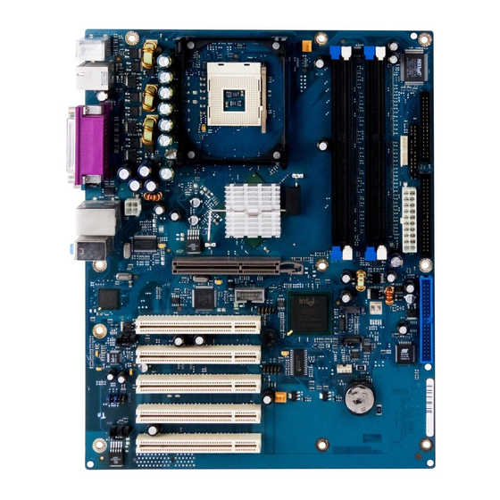
Übersicht/Overview Mainboard D1627/25 Diskettenlaufwerk / Floppy disk drive Interne Anschlüsse und Steckplätze / Internal Stromversorgungsüberwachung / connectors and slots Power supply control Bedienfeld / Front panel Stromversorgung / Power supply IDE-Laufwerke 3/4 / IDE-drives 3/4 IDE-Laufwerke 1/2 / IDE-drives 1/2 USB E/F Serial ATA2 Serial ATA1... -
Seite 9: Inhaltsverzeichnis
Inhalt Übersicht/Overview Mainboard D1627/25 Mainboard D1627/25 ........................1 Darstellungsmittel ........................1 Wichtige Hinweise ..........................2 Hinweise zu Baugruppen ......................2 Übersicht Leistungsmerkmale......................3 Besondere Merkmale.........................4 Kurzanleitung Mainboard einbauen....................6 Vor dem Einbau .........................6 Anschlüsse und Steckverbinder ....................8 Externe Anschlüsse...........................8 LAN-Anschluss ..........................8 2-, 4- oder 6-Kanal-Audiobetrieb ....................9 Interne Anschlüsse und Steckverbinder...................10 Festplatten-Anschluss ......................10 Pinbelegung interne Anschlüsse......................11... -
Seite 11: Mainboard D1627/25
Mainboard D1627/25 Ihr Mainboard ist in verschiedenen Ausbaustufen erhältlich. Abhängig von der Konfiguration Ihres Mainboards kann es vorkommen, dass Sie einige Hardware-Komponenten nicht vorfinden, obwohl diese in diesem Handbuch beschrieben sind. Weitere Informationen Informationen zum BIOS-Setup und zusätzliche Beschreibungen zu den Treibern finden Sie: •... -
Seite 12: Wichtige Hinweise
Wichtige Hinweise Wichtige Hinweise Bei eingebautem Mainboard müssen Sie das System öffnen, um Zugriff auf das Mainboard zu bekommen. Wie Sie das System zerlegen und wieder zusammenbauen, ist in der Betriebsanleitung des Systems beschrieben. Verbindungskabel zu Peripheriegeräten müssen über eine ausreichende Abschirmung verfügen. Beachten Sie die Sicherheitshinweise in der Betriebsanleitung des Systems. -
Seite 13: Übersicht Leistungsmerkmale
SmartCard Leseranschluss (USB / seriell) - / - - / - Temperaturüberwachung Systemüberwachung Unterstützung für Fujitsu Siemens Computers Tastatur mit Einschalttaste Interne Anschlüsse DIMM-Steckplätze (DDR 400/333/266 SDRAM) AGP-Steckplatz (8x, 32 Bit, 66 MHz, 1,5 V) PCI-Steckplatz (32 Bit, 33 MHz, 5 V und 3,3 V) CNR-Steckplatz (Type A, AC‘97 only) -
Seite 14: Besondere Merkmale
Mainboards besitzt oder unterstützt das Mainboard die nachfolgend beschriebenen Merkmale. Thermal Management und System Monitoring Ein von Fujitsu Siemens Computers entwickelter Mikrocontroller schützt Ihren PC zuverlässig gegen Schäden, die durch Überhitzung verursacht werden. Überhitzung kann den Verlust von Daten oder sogar Beschädigung des Prozessors zur Folge haben. - Seite 15 Recovery BIOS Wenn während eines BIOS-Updates ein Fehler auftritt (z. B. durch Stromausfall), ist das System-BIOS zerstört. Alle Fujitsu Siemens Computers Mainboards verfügen über ein Recovery-BIOS. Damit kann ein zerstörtes BIOS einfach wiederhergestellt werden. Eine genaue Anleitung finden Sie im Kapitel "BIOS-Recovery - System-BIOS wiederherstellen".
-
Seite 16: Kurzanleitung Mainboard Einbauen
Kurzanleitung Mainboard einbauen Wenn Sie das Mainboard einzeln gekauft haben, können Sie das Mainboard nach der folgenden Kurzanleitung in Ihr System einbauen. Die hier beschriebenen Tätigkeiten setzen Grundwissen über PC voraus und können nicht von einem Laien ausgeübt werden. Falls Sie sich nicht sicher sind, ob Sie ausreichend Fachwissen besitzen, so überlassen Sie diese Arbeiten einem Fachmann. -
Seite 17: Treiberinstallation
Kurzanleitung Mainboard einbauen Ê Sollte im Gehäuse kein passendes Anschlussfeld vorhanden sein, müssen Sie das mitgelieferte Anschlussfeld (1) einbauen. Achten Sie auf die Ausrichtung der Blende, damit die Anschlüsse dem Mainboard hinterher passen. Ê Setzen Sie das Mainboard an der Kante an, an der sich das Anschlussfeld befindet (2), und setzen Sie die Baugruppe dann ins Gehäuse ein (3). -
Seite 18: Anschlüsse Und Steckverbinder
Anschlüsse und Steckverbinder Die Position der Anschlüsse und Steckverbinder finden Sie auf der Seite "Umschlag/Cover". Die markierten Komponenten und Steckverbinder müssen nicht auf dem Mainboard vorhanden sein. Externe Anschlüsse Die Position der externen Anschlüsse finden Sie auf der Seite "Umschlag/Cover". Audioeingang (Line in), hellblau PS/2 Tastaturanschluss, violett oder Rear... -
Seite 19: 4- Oder 6-Kanal-Audiobetrieb
Externe Anschlüsse 2-, 4- oder 6-Kanal-Audiobetrieb Das Mainboard unterstützt einen 6-Kanal-Audioausgang (2 Front-, 2 Rear-, 1 Center- und 1 Subwoofer-Kanal). Damit ist es möglich, 4 oder 6 Lautsprecher anzuschließen und somit einen besseren Surround-Sound-Effekt zu erzielen. Treiber Für den 2-, 4- oder 6-Kanal-Audiobetrieb muss ein entsprechender Treiber installiert sein. Falls der Treiber noch nicht installiert ist, gehen Sie vor wie im Kapitel "Erweiterungen / Hochrüsten", Abschnitt "Treiber"... -
Seite 20: Einstellung Für 2-, 4- Oder 6-Kanal-Audiobetrieb Auswählen
Interne Anschlüsse und Steckverbinder Einstellung für 2-, 4- oder 6-Kanal-Audiobetrieb auswählen Abhängig vom Treiber für den Audiobetrieb und vom verwendeten Betriebssystem können Sie die Audioeigenschaften konfigurieren, z. B. unter Windows 2000 unter Start - Einstellungen - Systemsteuerung - Sounds und Multimedia. Interne Anschlüsse und Steckverbinder Die Position der internen Anschlüsse und Steckverbinder finden Sie auf der Seite "Umschlag/Cover". -
Seite 21: Pinbelegung Interne Anschlüsse
Pinbelegung interne Anschlüsse Pinbelegung interne Anschlüsse Im folgenden finden Sie die Pinbelegung einiger interner Anschlüsse in Deutsch und/oder Englisch. Einige der beschriebenen Anschlüsse können optional sein! Message LED 1) Power On/Off Sleep LED Bedienfeld / Front panel Power On Sleep LED 1) 3) HD-LED Achten Sie bei den LEDs auf die Polung. - Seite 22 Pinbelegung interne Anschlüsse IDE/ATA-Schnittstelle / IDE/ATA interface Signal Signal Reset drive (low asserted) Data 7 (high asserted) Data 8 (high asserted) Data 6 (high asserted) Data 9 (high asserted) Data 5 (high asserted) Data 10 (high asserted) Data 4 (high asserted) Data 11 (high asserted) Data 3 (high asserted) Data 12 (high asserted)
- Seite 23 Pinbelegung interne Anschlüsse CD audio Input Signal Left CD audio input CD GND CD GND Right CD audio input Power supply control Signal AC Outlet (high asserted) PS FAN Control (low asserted) PS FAN full on (low asserted) PS FAN Sense SMB CLK SMB DATA VCC EEPROM (+3,3V)
- Seite 24 Pinbelegung interne Anschlüsse USB E/F - dual channel (internal or external via special wire) Signal Signal Chipcardreader on VCC C VCC D Data negative C Data negative D Data positive C Data positive D Not connected G/H - dual channel (internal or external via special cable) Signal Signal...
-
Seite 25: Serial Port
Pinbelegung interne Anschlüsse Serial port 2 Signal Signal DCD 2 SIN 2 SOUT 2 DTR2 DSR 2 RTS 2 CTS 2 RI 2 Lüfter 1 / fan 1 (processor fan - only for 3 pin fans) Signal Controlled FAN voltage (0V, +6V, ... +12V, max. 1A) or fix Fan voltage (+12 V, max. -
Seite 26: Stromversorgung Atx / Power Supply Atx
Pinbelegung interne Anschlüsse Stromversorgung ATX / Power supply ATX Signal Signal +3.3V(P3V3P) +3.3V(P3V3P) +3.3V(P3V3P) -12V (P12VN) +5V (VCC) PS on (low asserted) +5V (VCC) Powergood (high asserted) -5V (5PVN) +5V Auxiliary (VCC Aux) +5V (VCC) +12V (P12VP) +5V (VCC) Zusätzliche Stromversorgung ATX12 V / Additional Power supply ATX12 V Signal Signal... -
Seite 27: Einstellungen Mit Schaltern Und Steckbrücken
Pinbelegung interne Anschlüsse Einstellungen mit Schaltern und Steckbrücken Ihr Mainboard ist alternativ mit Schaltern oder Steckbrücken bestückt. Die Position der Schalter oder Steckbrücken finden Sie auf der Seite "Umschlag/Cover". Schalter 1 = System- und BIOS-Setup-Passwort umgehen Schalter 2 = System-BIOS wiederherstellen 1 2 3 4 Schalter 3 = muss immer auf off gestellt sein Schalter 4 = muss immer auf off gestellt sein... -
Seite 28: Erweiterungen / Hochrüsten
• Celeron mit 400 MHz Prozessor System Bus (PSB) in der Bauform mPGA478 Eine aktuelle Liste der von diesem Mainboard unterstützten Prozessoren finden Sie im Internet unter: www.fujitsu-siemens.de/mainboards. Prozessor ausbauen/einbauen Ê Entfernen Sie einen eventuell vorhandenen Lüfter und den Kühlkörper. - Seite 29 Prozessor tauschen Kühlkörpermontage Verwenden Sie unbedingt Wärmeleitmaterial zwischen Prozessor und Kühlkörper. Wenn auf dem Kühlkörper bereits ein Wärmeleitpad (gummiartige Folie) aufgebracht ist, verwenden Sie dieses. Ansonsten müssen Sie eine sehr dünne Schicht Wärmeleitpaste auftragen. Wärmeleitpads können Sie nur einmal benutzen. Wenn Sie den Kühlkörper abnehmen, müssen Sie ihn reinigen und neue Wärmeleitpaste auftragen, bevor Sie ihn erneut montieren.
-
Seite 30: Hauptspeicher Hochrüsten
128 Mbytes bis 4 Gbyte DDR 400 SDRAM Modulgrößen: 128, 256, 512 oder 1024 Mbyte pro Modul Eine aktuelle Liste der für dieses Mainboard empfohlenen Speichermodule finden Sie im Internet unter: www.fujitsu-siemens.de/mainboards. Es muss mindestens ein Speichermodul eingebaut sein. Speichermodule mit unterschiedlicher Speicherkapazität können kombiniert werden. -
Seite 31: Agp-Grafikkarten Hochrüsten
AGP-Grafikkarten hochrüsten Speichermodul einbauen Ê Klappen Sie die Halterungen des entsprechenden Einbauplatzes an beiden Seiten nach außen. Ê Stecken Sie das Speichermodul in den Einbauplatz (1). Ê Klappen Sie dabei die seitlichen Halterungen hoch, bis sie am Speichermodul einrasten (2). Speichermodul ausbauen Ê... -
Seite 32: Pci-Karten Hochrüsten
PCI-Karten hochrüsten PCI-Karten hochrüsten Technische Daten: 32 Bit / 33 MHz PCI-Steckplätze 5 V und 3,3 V Versorgungsspannung 3,3 V Hilfsspannung PCI-Bus-Interrupts - Auswahl des richtigen PCI-Steckplatzes Um optimale Stabilität, Performance und Kompatibilität zu erreichen, vermeiden Sie die mehrfache Nutzung von ISA IRQs oder PCI IRQ Lines (IRQ Sharing). Sollte IRQ Sharing nicht zu umgehen sein, so müssen alle beteiligten Geräte und deren Treiber IRQ Sharing unterstützen. - Seite 33 PCI-Karten hochrüsten Controller or slot INT Mechanischer Steckplatz Onboard controller USB 1.1 AC97 PCI-Steckplatz Interrupt Line 1 (A) 2 (B) 3 (C) 4 (D) 5 (E) 6 (F) 7 (G) 8 (H) Verwenden Sie zuerst PCI-Steckplätze, die über eine einzige PCI IRQ Line verfügen (kein IRQ Sharing).
-
Seite 34: Lithium-Batterie Austauschen
PCI-Karten hochrüsten Lithium-Batterie austauschen Damit die Systeminformation dauerhaft gespeichert werden kann, ist eine Lithium-Batterie eingebaut, die den CMOS-Speicher mit Strom versorgt. Wenn die Spannung der Batterie zu niedrig ist oder die Batterie leer ist, wird eine entsprechende Fehlermeldung ausgegeben. Die Lithium- Batterie muss dann gewechselt werden. -
Seite 35: Bios-Update
BIOS-Update BIOS-Update Wann sollte ein BIOS-Update durchgeführt werden? Fujitsu Siemens Computers stellt neue BIOS-Versionen zur Verfügung, um die Kompatibilität zu neuen Betriebssystemen, zu neuer Software oder zu neuer Hardware zu gewährleisten. Außerdem können neue BIOS-Funktionen integriert werden. Ein BIOS-Update sollte auch immer dann durchgeführt werden, wenn ein Problem besteht, das sich durch neue Treiber oder neue Software nicht beheben lässt. -
Seite 36: Microcode-Update
Sicherheit für den Prozessor auf Fujitsu Siemens Computers Mainboards Wird der Prozessor mit einem alten oder falschen Microcode genutzt, kann ein fehlerfreier Betrieb nicht gewährleistet werden. Fujitsu Siemens Computers hat deshalb auf seinen Mainboards eine Funktion implementiert, die den Startvorgang unterbricht, falls kein passender Microcode für den installierten Prozessor vorhanden ist. -
Seite 37: Treiber
Treiber Microcode-Update unter DOS mit bootfähiger Microcode-Update-Diskette - Kurzbeschreibung Ê Laden Sie die Update-Datei von unserer Internet-Seite auf Ihren PC. Ê Legen Sie eine leere Diskette (1,44 MB) ein. Ê Führen Sie die Update-Datei unter DOS aus (z. B. 1495101.EXE). Ê... -
Seite 38: Anhang
Beseitigung des Fehlerzustandes setzen sich die Sicherungen wieder in den Ursprungszustand zurück. Strombedarf des Mainboards Sie benötigen für dieses Mainboard ein Pentium4-Netzteil nach der ATX12V-Spezifikation. Wenn Sie keinen PC von Fujitsu Siemens Computer haben, stellen Sie sicher, dass das Netzteil die benötigten Stromstärken zur Verfügung stellt. Quelle Spannung... -
Seite 39: Apm Und Acpi Systemstatus, Stromsparmodi
APM und ACPI Systemstatus, Stromsparmodi APM und ACPI Systemstatus, Stromsparmodi Systemstatus ACPI Power Strom- Aufwach- Status* Status verbrauch zeit Normaler Normal Betrieb Einfacher Standby blinkt Fast wie fast sofort Energie- Normal sparmodus Maximaler RAM-, ca. 5s Energie- Wake-up- sparmodus** Komponenten "Save-To-RAM"... -
Seite 40: Mainboard-Revision Und Bios-Version
Die Kompatibilität z. B. mit neuen Prozessoren kann abhängig von der verwendeten BIOS-Version oder dem Revision-Stand des Mainboards sein. Sie finden die CPU- und BIOS-Kompatibilitätslisten im Internet unter www.fujitsu-siemens.de/mainboards. Mainboard-Revision Der Revision-Stand des Mainboards identifiziert genau, welches Mainboard Sie besitzen. Sie finden... -
Seite 41: Fehlermeldungen
Available CPUs do not support the same bus frequency - System halted! Memory type mixing detected Non Fujitsu Siemens Memory Module detected - Warranty void There are more than 32 32 RDRAM devices in the system Überprüfen Sie, ob sich die Systemkonfiguration geändert hat. Korrigieren Sie diese gegebenenfalls. - Seite 42 Fehlermeldungen DMA test failed EISA CMOS not writable Extended RAM Failed at offset: nnnn Extended RAM Failed at address line: nnnn Failing Bits: nnnn Fail-Safe Timer NMI failed Multiple-bit ECC error occurred Memory decreased in size Memory size found by POST differed from EISA CMOS Single-bit ECC error occurred Software NMI failed System memory exceeds the CPU’s caching limit...
- Seite 43 Fehlermeldungen Missing or invalid NVRAM token Schalten Sie das Gerät aus und wieder ein. Wenn die Meldung weiterhin erscheint, wenden Sie sich bitte an Ihre Verkaufsstelle oder unseren Service. Monitor type does not match CMOS - RUN SETUP Stellen Sie im BIOS-Setup, im Menü Main, den Eintrag für den Bildschirmtyp richtig ein. On Board PCI VGA not configured for Bus Master Stellen Sie im BIOS-Setup, im Menü...
- Seite 44 Fehlermeldungen System battery is dead - Replace and run SETUP Tauschen Sie die Lithium-Batterie auf dem Mainboard aus und führen Sie die Einstellungen im BIOS-Setup erneut durch. System Cache Error - Cache disabled Schalten Sie das Gerät aus und wieder ein. Wenn die Meldung weiterhin erscheint, wenden Sie sich an Ihre Verkaufsstelle oder an unseren Service.
-
Seite 45: Glossar
Glossar Die unten aufgeführten Fachbegriffe bzw. Abkürzungen stellen keine vollständige Aufzählung aller gebräuchlichen Fachbegriffe bzw. Abkürzungen dar. Nicht alle hier aufgeführten Fachbegriffe bzw. Abkürzungen gelten für das beschriebene Mainboard. ACPI Advanced Configuration and Industrial Standard Architecture Power Management Interface AC'97 Audio Codec '97 Local Area Network Accelerated Graphics Port... - Seite 46 answers Technisches Handbuch / Technical Manual Mainboard D1627/25 Deutsch / English / Français...
- Seite 47 ...des questions techniques ou des problèmes ? Veuillez contacter : • Votre partenaire Commercial • Votre point de Vente Les dernières informations ainsi que les updates (p.ex. BIOS-Update) par rapport à nos cartes mères sont à votre disposition sur Internet : http://www.fujitsu-siemens.com/mainboards...
- Seite 49 Questo manuale è stato stampato su carta da riciclaggio. Denna handbok är tryckt på recyclingpapper. Dit handboek werd op recycling-papier gedrukt. Herausgegeben von/Published by Fujitsu Siemens Computers GmbH A26361-D1627-Z120-1-6319 Bestell-Nr./Order No.: Printed in the Federal Republic of Germany AG 0303...
- Seite 50 Deutsch English Mainboard D1627/25 Français Technisches Handbuch Technical Manual Ausgabe März 2003 Mars 2003 edition...
- Seite 51 Alle weiteren genannten Warenzeichen sind Warenzeichen oder eingetragene Warenzeichen der jeweiligen Inhaber und werden als geschützt anerkannt. Copyright Fujitsu Siemens Computers GmbH 2002 Alle Rechte vorbehalten, insbesondere (auch auszugsweise) die der Übersetzung, des Nachdrucks, der Wiedergabe durch Kopieren oder ähnliche Verfahren.
- Seite 53 Übersicht/Overview Mainboard D1627/25 Diskettenlaufwerk / Floppy disk drive Interne Anschlüsse und Steckplätze / Internal Stromversorgungsüberwachung / connectors and slots Power supply control Bedienfeld / Front panel Stromversorgung / Power supply IDE-Laufwerke 3/4 / IDE-drives 3/4 IDE-Laufwerke 1/2 / IDE-drives 1/2 USB E/F Serial ATA2 Serial ATA1...
- Seite 54 Contents Übersicht/Overview Mainboard D1627/25 ..................8 Mainboard D1627/25 ........................1 Notational conventions ......................1 Important notes..........................2 Information about boards ......................2 List of features...........................3 Special features.........................4 Brief instructions on installing mainboard...................6 Prior to installation ........................6 Interfaces and connectors ......................8 External ports ............................8 LAN connector...........................8 2, 4 or 6-channel audio mode ....................9 Internal ports and connectors ......................10 Hard disk connection .......................10...
-
Seite 56: Mainboard D1627/25
Mainboard D1627/25 Your mainboard is available in different configuration levels. Depending on the configuration chosen, some of the hardware components described may not be available on your mainboard. Additional information Information on the BIOS Setup and additional descriptions of the drivers are contained: •... -
Seite 57: Important Notes
Important notes Important notes With the mainboard installed you must open the system to access the mainboard. How to dismantle and reassemble the system is described in the operating manual accompanying the system. Connecting cables for peripherals must be adequately shielded to avoid interference. Observe the safety notes in the operating manual of your system. - Seite 58 SmartCard Reader Support (USB / serial) - / - - / - Temperature monitoring System Monitoring Fujitsu Siemens Computers Keyboard Power Button Support Internal ports DIMM slots (DDR 400/333/266 SDRAM) AGP Slot (8x, 32 bit, 66 MHz, 1.5 V) PCI slot (32 bit, 33 MHz, 5 V and 3.3 V) CNR Slot (Type A, AC‘97 only)
-
Seite 59: List Of Features
Thermal Management and System Monitoring A microcontroller developed by Fujitsu Siemens Computers reliably protects your PC against damage caused by overheating. Overheating can lead to the data loss or processor damage. - Seite 60 If an error occurs during a BIOS update (e.g. due to a power failure), the system BIOS will be destroyed. All Fujitsu Siemens Computers mainboards are equipped with a recovery BIOS. With it a destroyed BIOS can easily be restored. Exact instructions are provided in the chapter "BIOS Recovery - Recovering System BIOS".
-
Seite 61: Brief Instructions On Installing Mainboard
Brief instructions on installing mainboard If you have purchased a separate mainboard, you can install the mainboard in your system in accordance with the following brief instructions. The activities described here assume a basic knowledge of PCs and cannot be carried out by a layperson. -
Seite 62: Driver Installation
Brief instructions on installing mainboard Ê Should no suitable connection field be provided in the case, then you must install the connection field (1) provided. Ensure the plate is aligned properly so that the connections are suitable for the mainboard later. Ê... -
Seite 63: Interfaces And Connectors
Interfaces and connectors The positions of the interfaces and connectors are shown on page "Cover". The components and connectors marked are not necessarily present on the mainboard. External ports The positions of the external ports are shown on page "Cover". Audio input (Line in), light blue PS/2 keyboard port, purple or Rear... -
Seite 64: 2, 4 Or 6-Channel Audio Mode
External ports 2, 4 or 6-channel audio mode The mainboard supports a 6-channel audio output (2 Front, 2 Rear, 1 Centre and 1 Subwoofer channel). This makes it possible to connect 4 or 6 loudspeakers, and therefore to achieve a better surround-sound effect. -
Seite 65: Internal Ports And Connectors
Internal ports and connectors Selecting settings for 2, 4 or 6-channel audio mode Depending on the driver for the audio mode and from the operating system used, you can configure the audio properties, e.g. with Windows 2000 under Start - Settings - Control Panel - Sounds and Multimedia. -
Seite 66: Pin Assignment Of Internal Ports
Pin assignment of internal ports Pin assignment of internal ports The pin assignment of some internal connections is shown in English in the following. Some of the following connectors may be optional! Power On/Off Message LED 1) Sleep LED Front panel Power On Sleep LED 1) 3) - Seite 67 Pin assignment of internal ports IDE/ATA interface Signal Signal Reset drive (low asserted) Data 7 (high asserted) Data 8 (high asserted) Data 6 (high asserted) Data 9 (high asserted) Data 5 (high asserted) Data 10 (high asserted) Data 4 (high asserted) Data 11 (high asserted) Data 3 (high asserted) Data 12 (high asserted)
- Seite 68 Pin assignment of internal ports CD audio input Signal Left CD audio input CD GND CD GND Right CD audio input Power supply control Signal AC Outlet (high asserted) PS FAN Control (low asserted) PS FAN full on (low asserted) PS FAN Sense SMB CLK SMB DATA...
- Seite 69 Pin assignment of internal ports USB E/F - dual channel (internal or external via special wire) Signal Signal Chipcardreader on VCC C VCC D Data negative C Data negative D Data positive C Data positive D not connected G/H - dual channel (internal or external via special cable) Signal Signal...
-
Seite 70: Serial Port
Pin assignment of internal ports Serial Port 2 Signal Signal DCD 2 SIN 2 SOUT 2 DTR2 DSR 2 RTS 2 CTS 2 RI 2 Fan 1 (processor fan - only for 3 pin fans) Signal Controlled FAN voltage (0V, +6V, ... +12V, max. 1A) or fix Fan voltage (+12 V, max. - Seite 71 Pin assignment of internal ports Power supply ATX Signal Signal +3.3V(P3V3P) +3.3V(P3V3P) +3.3V(P3V3P) -12V (P12VN) +5V (VCC) PS on (low asserted) +5V (VCC) Powergood (high asserted) -5V (5PVN) +5V Auxiliary (VCC Aux) +5V (VCC) +12V (P12VP) +5V (VCC) Additional power supply ATX12 V Signal Signal +12 V...
-
Seite 72: Settings With Switches And Jumpers
Pin assignment of internal ports Settings with switches and jumpers Your mainboard is equipped with switches or jumpers. The positions of the switches or jumpers are shown on page "Cover". Switch 1 = Skipping system and BIOS Setup password Switch 2 = System BIOS recovery 1 2 3 4 Switch 3 = must be set to off Switch 4 = must be set to off... -
Seite 73: Add-On Modules / Upgrading
• Celeron with 400 MHz Processor System Bus (PSB) in the mPGA478 design A current list of the processors supported by this mainboard is available on the Internet at: www.fujitsu-siemens.com/mainboards. Removing and installing processors Ê Remove the fan that there may be and the heat sink. -
Seite 74: Mounting Heat Sink
Replacing processor Mounting heat sink Be sure to use heat conducting material between the processor and the heat sink. If a heat conducting pad (rubber-like foil) is already applied to the heat sink, then use it. Otherwise you must apply a very thin layer of heat conducting paste. Heat conducting pads can only be used once. -
Seite 75: Upgrading Main Memory
128, 256, 512 or 1024 Mbyte for one socket A current list of the memory modules recommended for this mainboard is available on the Internet at: www.fujitsu-siemens.com/mainboards. At least one memory module must be installed. Memory modules with different memory capacities can be combined. -
Seite 76: Upgrading Agp Screen Controllers
Upgrading AGP screen controllers Installing a memory module Ê Push the holders on each side of the memory slot outwards. Ê Insert the memory module into the location (1). Ê At the same time flip the lateral holders upwards until the memory module snaps in place (2). Removing a memory module Ê... -
Seite 77: Adding Pci Cards
Adding PCI cards Adding PCI cards Technical data: 32 bit / 33 MHz PCI slots 5 V and 3.3 V supply voltage 3.3 V auxiliary voltage PCI bus interrupts - Selecting correct PCI slot To achieve optimum stability, performance and compatibility, avoid the multiple use of ISA IRQs or PCI IRQ Lines (IRQ sharing). - Seite 78 Adding PCI cards Controller or slot INT Mechanical slot Onboard controller USB 1,1 AC97 PCI slot Interrupt Line 1 (A) 2 (B) 3 (C) 4 (D) 5 (E) 6 (F) 7 (G) 8 (H) Use the first PCI slots that have a single PCI IRQ Line (no IRQ sharing). If you must use another PCI slot with IRQ sharing, check whether the expansion card properly supports IRQ sharing with the other devices on this PCI IRQ Line.
-
Seite 79: Replacing The Lithium Battery
Adding PCI cards Replacing the lithium battery In order to permanently save the system information, a lithium battery is installed to provide the CMOS-memory with a current. A corresponding error message notifies the user when the charge is too low or the battery is empty. The lithium battery must then be replaced. Incorrect replacement of the lithium battery may lead to a risk of explosion! The lithium battery may be replaced only with an identical battery or with a type recommended by the manufacturer. -
Seite 80: Bios Update
BIOS update BIOS update When should a BIOS update be carried out? Fujitsu Siemens Computers makes new BIOS versions available to ensure compatibility to new operating systems, new software or new hardware. In addition, new BIOS functions can also be integrated. -
Seite 81: Microcode Update
Safety for processor on Fujitsu Siemens Computers mainboards If the processor uses an old or incorrect microcode, error-free operation cannot be ensured. Fujitsu Siemens Computers has therefore implemented a function on its mainboards that interrupts the booting process if no suitable microcode is available for the installed processor. -
Seite 82: Drivers
Drivers Microcode update under DOS with bootable microcode update floppy disk - brief description Ê Download the update file from out website to your PC. Ê Insert an empty floppy disk (1.44 MB). Ê Run the update file under DOS (e.g. 1495101.EXE). Ê... -
Seite 83: Annex
Mainboard current requirement You require a Pentium4 power supply nit as per the ATX12V specification for this mainboard. If you do not have a PC from Fujitsu Siemens Computer, make sure that the power supply unit provides the required amperages. -
Seite 84: Apm And Acpi System Status, Energy-Saving Modes
APM and ACPI system status, energy-saving modes APM and ACPI system status, energy-saving modes System status ACPI Power Power Wake-up Status* Status consumption time Normal Normal operation Simple energy- Standby flashin Almost like Almost saving mode normal immediate Maximum RAM, ca. -
Seite 85: Mainboard Revision And Bios Version
The compatibility, e.g. with new processors, can be independent of the BIOS version or the revision status of the mainboard used. The CPU and BIOS compatibility lists are available on the Internet at www.fujitsu-siemens.de/mainboards. Mainboard Revision The revision status of the mainboard exactly identifies which mainboard you have. It is indicated on... -
Seite 86: Error Messages
Available CPUs do not support the same bus frequency - System halted! Memory type mixing detected Non Fujitsu Siemens Memory Module detected - Warranty void There are more than 32 32 RDRAM devices in the system Check whether the system configuration has changed. If necessary, correct the settings. - Seite 87 Error messages DMA test failed EISA CMOS not writable Extended RAM Failed at offset: nnnn Extended RAM Failed at address line: nnnn Failing Bits: nnnn Fail-Safe Timer NMI failed Multiple-bit ECC error occurred Memory decreased in size Memory size found by POST differed from EISA CMOS Single-bit ECC error occurred Software NMI failed System memory exceeds the CPU’s caching limit...
- Seite 88 Error messages Missing or invalid NVRAM token Switch the device off and on again. If the message is still displayed, please contact your sales outlet or customer service centre. Monitor type does not match CMOS - RUN SETUP Correct the entry for the monitor type in the Main menu of the BIOS Setup. On Board PCI VGA not configured for Bus Master In the BIOS Setup, in the Advanced menu, submenu PCI Configuration, set the Shared PCI Master Assignment entry to VGA.
- Seite 89 Error messages System battery is dead - Replace and run SETUP Replace the lithium battery on the mainboard and redo the settings in the BIOS Setup. System Cache Error - Cache disabled Switch the device off and on again. If the message is still displayed, please contact your sales outlet or customer service centre.
-
Seite 90: Glossary
Glossary The technical terms and abbreviations given below represent only a selection of the full list of common technical terms and abbreviations. Not all technical terms and abbreviations listed here are valid for the described mainboard. ACPI Advanced Configuration and Industrial Standard Architecture Power Management Interface AC'97... - Seite 91 Sommaire Mainboard D1627/25........................... 1 Symboles............................1 Remarques importantes ........................2 Remarques relatives aux cartes ....................2 Aperçu des caractéristiques ......................... 3 Caractéristiques ........................... 4 Notice succincte Monter la carte mère ....................6 Avant le montage ......................... 6 Ports et connecteurs.......................... 8 Ports externes ............................
-
Seite 93: Mainboard D1627/25
Mainboard D1627/25 Votre carte mère est disponible en plusieurs niveaux d'équipement. Selon la configuration de votre carte mère, il est possible que certains composants matériels ne soient pas présents, bien que décrits dans le présent manuel. Autres informations Vous trouverez des informations sur le Setup du BIOS ainsi que des descriptions supplémentaires des pilotes dans : •... -
Seite 94: Remarques Importantes
Remarques importantes Remarques importantes Si la carte mère est intégrée, vous devez ouvrir le système pour y accéder. La façon de démonter et de remonter le système est décrite dans le manuel d’utilisation du système. Les câbles de données vers les périphériques doivent disposer d’un blindage suffisant. Veuillez respecter les consignes de sécurité... - Seite 95 - / - - / - Surveillance de la température Surveillance du système Support pour le clavier Fujitsu Siemens Computers avec touche de mise sous tension Ports internes Ports DIMM (DDR 400/333/266 SDRAM) Port AGP (8x, 32 bits, 66 MHz, 1,5 V) Port PCI (32 bits, 33 MHz, 5 V et 3,3 V) Port CNR (type A, AC‘97 uniquement)
- Seite 96 Gestion thermique et surveillance du système Grâce au microcontrôleur conçu par Fujitsu Siemens Computers, votre PC est efficacement protégé contre toute détérioration due à une surchauffe. La surchauffe peut provoquer la perte de données, voire même endommager le processeur. Un réglage et une surveillance judicieux des ventilateurs permet d’éviter les nuisances...
-
Seite 97: Aperçu Des Caractéristiques
En cas d’erreur lors d’une mise à jour du BIOS (suite à une panne de courant, p. ex.), le BIOS système est détruit. Toutes les cartes mères de Fujitsu Siemens Computers disposent d’un ‘Recovery BIOS’. Le BIOS détruit peut ainsi être facilement restauré. -
Seite 98: Notice Succincte Monter La Carte Mère
Notice succincte Monter la carte mère Si vous avez acheté la carte mère séparément, vous pouvez la monter sur votre système en suivant les quelques instructions ci-dessous. Les tâches décrites ci-après présupposent une connaissance élémentaire des PC et ne peuvent être exécutées par des profanes. -
Seite 99: Installation Des Pilotes
Notice succincte Monter la carte mère Montage Ê Dans la mesure du possible, équipez déjà la carte mère, avant son montage dans le boîtier, d’un processeur, d’un refroidisseur et de modules d’extension mémoire. Vous trouverez d'autres informations à ce sujet dans le chapitre "Remplacer le processeur". Ê... -
Seite 100: Ports Et Connecteurs
Ports et connecteurs Vous trouverez l’emplacement des ports et des connecteurs sur la page "Couverture/Cover". Les composants et connecteurs marqués ne doivent pas être disponibles sur la carte mère. Ports externes Vous trouverez l’emplacement des ports externes sur la page "Couverture/Cover". Entrée audio (Line in), bleu ciel Port clavier PS/2, violet ou Rear... -
Seite 101: Fonction Audio À 2, 4 Ou 6 Canaux
Ports externes Fonction audio à 2, 4 ou 6 canaux La carte mère supporte une sortie audio à 6 canaux (2 canaux frontaux, 2 canaux arrières, 1 canal central et 1 canal subwoofer). Vous pouvez ainsi connecter 4 ou 6 haut-parleurs et obtenir un meilleur effet de son enveloppant (effet "surround"). -
Seite 102: Ports Internes Et Connecteurs
Ports internes et connecteurs Sélectionner les réglages pour la fonction audio à 2, 4 ou 6 canaux Selon le pilote utilisé pour la fonction audio et en fonction du système d’exploitation, vous pouvez configurer les propriétés audio, p. ex. sous Windows 2000 dans Démarrer - Paramètres - Panneau de configuration –... -
Seite 103: Affectation Des Broches Des Ports Internes
Affectation des broches des ports internes Affectation des broches des ports internes Vous trouverez ci-dessous l’affectation des broches de quelques ports internes, en français et/ou anglais. Certains ports décrits peuvent être optionnels ! Message LED 1) Power On/Off Panneau de commande / Front panel Sleep LED Power On Sleep... - Seite 104 Affectation des broches des ports internes Interface IDE/ATA / interface IDE/ATA Code PIN Signal Code PIN Signal Reset drive (low asserted) Data 7 (high asserted) Data 8 (high asserted) Data 6 (high asserted) Data 9 (high asserted) Data 5 (high asserted) Data 10 (high asserted) Data 4 (high asserted) Data 11 (high asserted)
- Seite 105 Affectation des broches des ports internes CD entrée audio Code Signal Left CD audio input CD GND CD GND Right CD audio input Contrôle de l'alimentation Code Signal AC Outlet (high asserted) PS FAN Control (low asserted) PS FAN full on (low asserted) PS FAN Sense SMB CLK SMB DATA...
- Seite 106 Affectation des broches des ports internes USB E/F - dual channel (internal or external via special wire) Code PIN Signal Code PIN Signal Chipcardreader on VCC C VCC D Data negative C Data negative D Data positive C Data positive D Not connected USB G/H - dual channel (internal or external via special cable)
- Seite 107 Affectation des broches des ports internes Serial Port 2 Code Signal Code Signal DCD 2 SIN 2 SOUT 2 DTR2 DSR 2 RTS 2 CTS 2 RI 2 Ventilateur 1 / fan 1 (processor fan - only for 3 pin fans) Code Signal Controlled FAN voltage (0V, +6V, ...
- Seite 108 Affectation des broches des ports internes Alimentation électrique ATX / Power supply ATX Code PIN Signal Code PIN Signal +3.3V(P3V3P) +3.3V(P3V3P) +3.3V(P3V3P) +12V (P12VP) +5V (VCC) PS on (low asserted) +5V (VCC) Powergood (high asserted) -5V (5PVN) +5V Auxiliary (VCC Aux) +5V (VCC) +12V (P12VP) +5V (VCC)
-
Seite 109: Réglages Avec Interrupteurs Et Cavaliers
Affectation des broches des ports internes Réglages avec interrupteurs et cavaliers Votre carte mère est équipée des interrupteurs ou des cavaliers. L’emplacement des interrupteurs ou des cavaliers est indiqué sur la page "Couverture/Cover". Interrupteur 1 = Utiliser le mot de passe du système et du Setup du BIOS Interrupteur 2 = restaurer le BIOS système 1 2 3 4... -
Seite 110: Extensions / Mises À Niveau
• Celeron avec processeur bus système (PSB) à 400 MHz dans un socket mPGA478 Vous trouverez une liste actualisée des processeurs supportés par cette carte mère sur Internet à l'adresse suivante : www.fujitsu-siemens.com/mainboards. Monter/démonter le processeur Ê Retirez le ventilateur éventuel ainsi que le refroidisseur. -
Seite 111: Montage Du Refroidisseur
Remplacer le processeur Montage du refroidisseur Utilisez impérativement un matériau conducteur de chaleur entre le processeur et le refroidisseur. Si un film (en caoutchouc) conducteur de chaleur a déjà été apposé sur le refroidisseur, utilisez-le. Si ce n’est pas le cas, appliquez une très fine couche d’enduit conducteur de chaleur. Vous ne pouvez utiliser les films conducteurs de chaleur qu’une seule fois. -
Seite 112: Etendre La Mémoire Vive
128, 256, 512 ou 1024 Moctets par module Vous trouverez une liste actualisée des modules d’extension mémoire recommandés pour cette carte mère sur Internet à l’adresse suivante : www.fujitsu-siemens.com/mainboards. Au moins un module d’extension mémoire doit être monté. Il est possible de combiner des modules d’extension mémoire de capacités différentes. - Seite 113 Etendre la mémoire vive Monter le module d’extension mémoire Ê Ecartez les clips de fixation de part et d’autre du logement correspondant. Ê Poussez le module d'extension mémoire dans son logement (1). Ê Relevez les clips de fixation latéraux jusqu’à ce qu’ils s’encastrent sur le module d’extension mémoire (2).
-
Seite 114: Monter Des Cartes Graphiques Agp
Monter des cartes graphiques AGP Monter des cartes graphiques AGP Caractéristiques techniques : Le port AGP supporte les modes 4x/8x avec 32 bits et 66 MHz. Seules les cartes graphiques AGP 1, 5 V sont supportées. Certaines cartes graphiques AGP 3,3 V plus anciennes ont été codées comme des cartes graphiques AGP 1,5 V. - Seite 115 Monter des cartes PCI Cartes d’extension multifonctions ou cartes d’extension avec pont PCI-PCI intégré : Ces cartes d’extension requièrent jusqu’à quatre interruptions PCI : INT A, INT B, INT C, INT D. Le nombre et la nature des interruptions utilisées figurent dans la documentation livrée avec la carte. L’affectation des interruptions PCI aux lignes PCI IRQ est reprise dans le tableau suivant : Contrôleur ou slot INT Emplacement mécanique...
-
Seite 116: Remplacer La Pile Au Lithium
Monter des cartes PCI Remplacer la pile au lithium Afin de permettre une sauvegarde durable des informations système, une pile au lithium est intégrée qui alimente la mémoire CMOS en courant. Lorsque la tension de la pile est trop faible ou que la pile est vide, un message d’erreur approprié... -
Seite 117: Bios - Actualisation
Où se procurer des mises à jour du BIOS ? Les mises à jour du BIOS sont disponibles sur Internet à l’adresse suivante : www.fujitsu- siemens.com/mainboards. Comment fonctionne une mise à jour du BIOS ? Deux possibilités s'offrent à... -
Seite 118: Bios-Recovery - Restaurer Le Bios Système
BIOS-Recovery - Restaurer le BIOS système BIOS-Recovery - Restaurer le BIOS système Tous les réglages du BIOS sont ramenés à des valeurs par défaut. Ê Démontez l’appareil comme décrit dans le manuel d’utilisation. Ê Réglez l’interrupteur pour "la restauration du BIOS système" en position MARCHE. Ê... -
Seite 119: Pilotes
Si le processeur utilisé comporte un microcode ancien ou erroné, le fonctionnement irréprochable de la carte mère n’est pas garanti. Fujitsu Siemens Computers a donc doté ses cartes mères d’une fonctionnalité qui interrompt la procédure de démarrage si aucun microcode n’est adapté au processeur installé. -
Seite 120: Annexe
Consommation électrique de la carte mère Pour cette carte mère, vous avez besoin d’un bloc d’alimentation Pentium4 conforme aux normes ATX12V. Si vous ne disposez pas d’un PC de Fujitsu Siemens Computers, assurez-vous que le bloc d’alimentation offre bien les ampérages requis. -
Seite 121: Etat Du Système Apm Et Acpi, Modes D'économie D'énergie
Etat du système APM et ACPI, modes d’économie d’énergie Etat du système APM et ACPI, modes d’économie d’énergie Etat du Etat ACPI Etat Consommati Temps de système Power on électrique réveil Fonctionnement Actif Normal normal Mode Standby clignot Presque Presque d’économie normal immédiate... -
Seite 122: Révision De La Carte Mère Et Version Du Bios
Le niveau de compatibilité avec de nouveaux processeurs, par exemple, peut dépendre de la version du BIOS utilisé ou du niveau de révision de la carte mère. Les listes de compatibilité processeur - BIOS sont disponibles sur Internet à l'adresse suivante : www.fujitsu- siemens.com/mainboards. -
Seite 123: Messages D'erreur
Available CPUs do not support the same bus frequency - System halted! Memory type mixing detected Non Fujitsu Siemens Memory Module detected - Warranty void There are more than 32 32 RDRAM devices in the system Vérifiez si la configuration du système a changé. Le cas échéant, corrigez-les. - Seite 124 Messages d’erreur DMA test failed EISA CMOS not writable Extended RAM Failed at offset: nnnn Extended RAM Failed at address line: nnnn Failing Bits: nnnn Fail-Safe Timer NMI failed Multiple-bit ECC error occurred Memory decreased in size Memory size found by POST differed from EISA CMOS Single-bit ECC error occurred Software NMI failed System memory exceeds the CPU’s caching limit...
- Seite 125 Messages d’erreur Missing or invalid NVRAM token Mettez l’appareil hors tension puis à nouveau sous tension. Si ce message réapparaît encore, adressez-vous à votre revendeur ou à notre S.A.V. Monitor type does not match CMOS - RUN SETUP Dans le menu Main du Setup du BIOS, corrigez l’entrée pour le type d’écran. On Board PCI VGA not configured for Bus Master Dans sous-menu PCI Configuration du menu Advanced du Setup du BIOS, réglez l’entrée Shared PCI Master Assignment sur VGA.
- Seite 126 Messages d’erreur System battery is dead - Replace and run SETUP Remplacez la pile au lithium sur la carte mére et recommencez les réglages dans le Setup du BIOS. System Cache Error - Cache disabled Mettez l’appareil hors tension puis à nouveau sous tension. Si ce message réapparaît encore, adressez-vous à...
-
Seite 127: Glossaire
Glossaire La liste des termes techniques et des abréviations ci-dessous n’est pas exhaustive. Les notions ou abréviations spécifiques énumérées ci-après ne s’appliquent pas toutes à la carte mère décrite. ACPI Advanced Configuration and Intelligent Drive Electronics Power Interface AC'97 Audio Codec '97 IPSEC Internet Protocol Security Accelerated Graphics Port...