Siko IV28M/1 Originalmontageanleitung

Verwandte Anleitungen für Siko IV28M/1


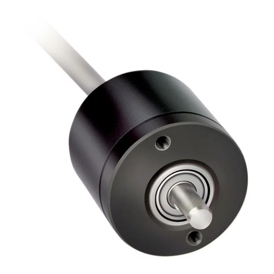
Inhaltszusammenfassung für Siko IV28M/1
- Seite 1 IV28M/1 Inkrementalgeber Deutsch Originalmontageanleitung Seite 2 Incremental encoder English Translation of the Original Installation Instructions page 15 186/15...
-
Seite 2: Inhaltsverzeichnis
5 Inbetriebnahme 6 Ausgangsschaltungen 6.1 Ausgangssignale / Impulsbild 7 Transport, Lagerung, Wartung und Entsorgung 8 Zubehör Anschluss-Stecker 8.1 Gegenstecker gerade/gewinkelt inklusive Kabel 8.2 Gegenstecker M16 gerade 9 Technische Daten IV28M/1 · Datum 22.05.2015 · Art. Nr. 84362 · Änd. Stand 186/15... -
Seite 3: Dokumentation
Todesfolge, Sachschäden oder ungeplanten Gerätereaktionen führen können, sofern Sie die gegebenen Anweisungen missachten. Gefährdungen, die zu schweren Körperverletzungen, Sachschäden oder WARNUNG ungeplanten Gerätereaktionen führen können, sofern Sie die gegebenen Anweisungen missachten. IV28M/1 · Datum 22.05.2015 · Art. Nr. 84362 · Änd. Stand 186/15... -
Seite 4: Zielgruppe
Geräte/Systeme gemäß den Standards der Sicherheitstech- nik in Betrieb zu nehmen, zu erden und zu kennzeichnen. 2.4 Grundlegende Sicherheitshinweise Explosionsgefahr GEFAHR ` Inkrementalgeber nicht in explosionsgefährdeten Zonen einsetzen. IV28M/1 · Datum 22.05.2015 · Art. Nr. 84362 · Änd. Stand 186/15... -
Seite 5: Identifikation
Unsachgemäße Montage (z. B. Spannungen an der Welle) führt zu zusätz- licher Erwärmung und langfristig zur Zerstörung des Inkrementalgeber. ` Sorgen Sie für einen geringen Wellen- und Winkelversatz zwischen Welle und Aufnahmebohrung durch geeignete Fertigungsmaßnahmen. IV28M/1 · Datum 22.05.2015 · Art. Nr. 84362 · Änd. Stand 186/15... - Seite 6 (Bohren, Fräsen, usw.). Hierdurch kann es zu schweren Beschädigun- gen der inneren Teile des Gebers kommen. • Unzulässige axiale oder radiale Belastung der Welle. • Unsachgemäße Befestigung des Gebers. Abb. 1: Montagehinweise IV28M/1 · Datum 22.05.2015 · Art. Nr. 84362 · Änd. Stand 186/15...
-
Seite 7: Elektrische Installation
Daten in Kapitel zu entnehmen. Anschlussarten • E1: offene Kabelenden • E6X: 7 bzw. 12 pol. Stiftkontakt (M16) Zubehör Gegenstecker und Kabelverlängerungen siehe Kapitel 8. IV28M/1 · Datum 22.05.2015 · Art. Nr. 84362 · Änd. Stand 186/15... - Seite 8 - - - B, G, J, L • E7: 5 pol. Stiftkontakt (M9) Belegung Ausgangsschaltung PP Signal Pin E7 Ansichtseite = Steckseite Stiftkontakt IV28M/1 · Datum 22.05.2015 · Art. Nr. 84362 · Änd. Stand 186/15...
-
Seite 9: Inbetriebnahme
(z. B. Steuerung) eingeschaltet werden, um Latchup-Effekte an den Ausgängen des Gebers zu vermeiden. ` Nehmen Sie den Geber elektrisch in Betrieb. 6 Ausgangsschaltungen Abb. 2: Ausgangsschaltung PP IV28M/1 · Datum 22.05.2015 · Art. Nr. 84362 · Änd. Stand 186/15... -
Seite 10: Ausgangssignale / Impulsbild
Impulszahlen 36, 50, 100, 150: 20 kHz Impulszahlen 200 ... 800: 100 kHz Impulszahlen 850 ... 1000: 250 kHz Bedingt durch das interne Interpolationsverfahren können im Stillstand ACHTUNG Impulse mit der max. Impulsfrequenz auftreten! IV28M/1 · Datum 22.05.2015 · Art. Nr. 84362 · Änd. Stand 186/15... -
Seite 11: Transport, Lagerung, Wartung Und Entsorgung
Stoffe und sind zugleich Wertstoffträger. Der Inkrementalgeber muss deshalb nach seiner endgültigen Stilllegung einem Recycling zuge- führt werden. Die Umweltrichtlinien des jeweiligen Landes müssen hierzu beachtet werden. IV28M/1 · Datum 22.05.2015 · Art. Nr. 84362 · Änd. Stand 186/15... -
Seite 12: Zubehör Anschluss-Stecker
über Litzen stülpen, zusammendrü- cken und auf stecken. Schlitz und Nut müssen deckungs- gleich sein. drücken, überstehender Schirm abschneiden. aufschieben und mittels Montagewerkzeug verschrau- ben. stecken, beides in schieben. verschrauben. schieben. IV28M/1 · Datum 22.05.2015 · Art. Nr. 84362 · Änd. Stand 186/15... -
Seite 13: Technische Daten
Ausgangssignalpegel RS422 A spez. LD24, LD5 Ausgangssignalpegel ≥29.2 V DC PP, OP (UB = 30 V, I = -30 mA) high Ausgangssignalpegel low ≤0.5 V DC PP, OP (UB = 30 V, I = 30 mA) IV28M/1 · Datum 22.05.2015 · Art. Nr. 84362 · Änd. Stand 186/15... - Seite 14 Steckverbinder 5/6/7/12-polig Umgebungsbedingungen Ergänzung Umgebungstemperatur -20 … 70 °C Lagertemperatur -20 … 80 °C Schutzart IP54 EN 60529 Schockfestigkeit 2000 m/s , 6 ms EN 60068-2-27 Vibrationsfestigkeit 100 m/s , 50 Hz EN 60068-2-6 IV28M/1 · Datum 22.05.2015 · Art. Nr. 84362 · Änd. Stand 186/15...
- Seite 28 SIKO GmbH Weihermattenweg 2 79256 Buchenbach Telefon/Phone + 49 7661 394-0 Telefax/Fax + 49 7661 394-388 E-Mail info@siko.de Internet www.siko-global.com Service support@siko.de...