Werbung
Quicklinks
3.2 REMPLACEMENT DE LA PILE
1
Le remplacement de la pile 9V est impératif lorsque l'icone
est affichée. Changer la pile en respectant la polarité.
3.3 REMPLACEMENT DES FUSIBLES
Le multimètre est protégé par un fusible de 500mA - 250V -
5∗20 mm et un fusible 10A.
4. CARACTERISTIQUES
2
OF F
V
V
6 0 0
6 0 0
2 0 0
2 0 0
2 0
2 0 0 0 K
4.1 CARACTERISTIQUES GENERALES
2 0 0 0 m
2 0 0 K
Mesure des valeurs
2 0 0 m
2 0 K
3
1 0 A
2 0 0 0
2 0 0
Afficheur
2 0 0 m
W
2 0 m
Sélection de gammes
2 0 0 0 µ
9 V
A
2 0 0 µ
1 ,5 V
Indication de polarité
O F F
4
Ba tt .
Fonction additionnelle
1 0 A
CO M
V W m A
Indication d'usure
pile
1 0 A MA X
F U SED
1 5 s
CA T II
F US ED
3 0 0 V
Environnement de
travail
5
Conditions de
stockage
Alimentation
électrique
FRANÇAIS
Dimensions
Masse
1. PRESENTATION
Fourniture livrée
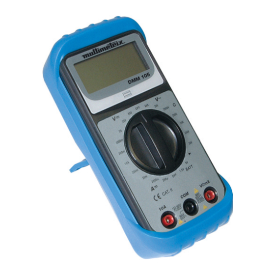
1.1 FACE AVANT
Rep.
Fonction
1.
Afficheur à cristaux liquides 2000 points
2.
Sélecteur rotatif de fonction
4.2 CARACTERISTIQUES TECHNIQUES
OFF : multimètre hors-tension
Conditions de références : 18°C - 28°C ; RH < 80 %,
3.
Borne courant 10 ADC
absence de condensation.
4.
Borne négative noire (-) COM
Norme : NF EN 61010-1, 300 V, CAT II pol. 2.
5.
Borne positive rouge (+), 300V max.AC/DC et
µA
µA
courant µA/mA DC
mA
mA
A
1.2 FACE ARRIERE
Précision (DCA)
Vis de fermeture
Précision (ACA)
Pile 9V 6F22
Zin
Fusibles 5 x 20 mm 0,2 A / 250V ou 6 x 25 mm 10A / 250V
V
V
Résolution (V)
Précision (DCV)
2. UTILISATION
Précision
(ACV)
R. in (MΩ)
2.1 MISE EN SERVICE DU MULTIMETRE
Positionner le sélecteur sur une position autre que OFF.
Ω
Ω
Résolution(Ω)
2.2 ARRET DU MULTIMETRE
Précision
Positionner le sélecteur sur OFF.
(+/-R%+/-dgt)
2.3 MESURE DE TENSION
Protection
250 V DC/AC
1.
Positionner le sélecteur sur une fonction de tension.
U <> 2.4V
2.
Insérer le connecteur noir dans la borne COM, le
Courant<>1± 0.6mA
rouge dans la borne V et prendre la mesure.
Protection
250V DC/AC
3.
Lire la valeur de la tension. En mode DC, COM
Test
1.5V / Courant
correspond au (-).
Battery
charge <> 100 mA /
2.4 MESURE DE COURANT
15Ω + 0.2 A fusible
1.
Positionner le commutateur sur une fonction de
courant.
2.
Insérer le connecteur noir dans la borne COM et le
rouge dans la borne :
- µ/mA pour un courant inférieur à 200 mA,
- 10A pour un courant supérieur à 200 mA.
1. INTRODUCTION
3.
Appliquer les pointes de touche et lire la valeur du
courant. En mode DC, COM correspond au (-).
2.5 MESURE DE RESISTANCE
1.1 FRONT VIEW
1.
Positionner le sélecteur sur :
No.
Function
2.
Insérer le connecteur noir dans la borne noire COM et
1.
2000 count liquid crystal display
le rouge dans la borne rouge Ω.
2.
Rotary function selector switch
3.
Appliquer les pointes de touche sur le circuit ou le
OFF: multimeter OFF
conducteur.
3.
10A DC current terminal
2.6 TEST DE DIODE
4.
Black COM negative terminal (-)
1.
Positionner le sélecteur sur :
5.
300V max red positive terminal (+) and µA/mA DC
2.
Insérer le connecteur noir dans la borne noire COM et
current terminal
le rouge dans la borne rouge Ω.
3.
Procéder à l'essai en direct.
4.
Procéder à l'essai en inverse.
1.2 REAR VIEW
Nota : Les jonctions E, B et C de transistors peuvent être
testées de la sorte.
Locking screw
Battery (1 x 9V 6F22)
Fuses
2.7 TEST DE PILES
1.
Connecter la pointe de touche noire sur la borne
« COM ».
2.
Connecter la pointe de touche rouge sur la borne
« VΩmA ».
2.1 TO USE THE MULTIMETER
3.
Positionner le commutateur sur la position
Set the selector to any position other than OFF.
« 1.5V Batt. » pour une pile de type AA ou sur la
position « 9V Batt. » pour une pile de type IEC 6F22.
2.2 TO STOP THE MULTIMETER
La tension lue correspond à la tension « en charge »
Set the selector to OFF.
de la pile. Une pile usée affichera une valeur
2.3 TO MEASURE VOLTAGE
inférieure à la tension nominale affichée.
1.
Set the selector to a voltage function (indicated in red).
4.
La mesure réalisée, mettre le commutateur sur la
2.
Insert the black connector in the black COM terminal
position « OFF ».
and the red connector in the V terminal .
3. REMPLACEMENT PILE ET FUSIBLES
3.
Take the voltage reading. In DC mode, COM
corresponds to (-).
2.4 TO MEASURE CURRENT
3.1 DEMONTAGE ET REMONTAGE DU COUVERCLE
1.
Set the selector to a current function.
1.
Déconnecter les pointes de touche.
2.
Insert the black connector in the black COM terminal
2.
Positionner le commutateur sur OFF.
and the red connector in one of the following terminals:
3.
Retirer les 3 vis de fixation du couvercle.
- µ/mA for currents less than 200mA,
4.
Remonter en sens inverse.
- 10A for currents greater than 200mA.
3.
Apply the contact points and take the reading for the
current. In DC mode, COM corresponds to (-).
2.5 TO MEASURE RESISTANCE
1.
Set the selector to :
2.
Insert the black connector in the black COM terminal
and the red connector in the red Ω terminal
3.
Apply the contact points to the circuit or the conductor.
2.6 DIODE TEST
1.
Set the selector to :
2.
Insert the black connector in the black COM terminal
and the red connector in the red Ω terminal.
3.
Make a direct test.
4.
Test in reverse.
Tension et courant continus
NB: Transistor joints E, B and C can be tested in this way.
tension alternative, résistance,
test de diode et de pile
2.7 BATTERY TEST
2000 points (3 digits ½)
1.
Connect the black test lead to the « COM » socket.
2.
Connect the red test lead to the « VΩmA » socket.
manuelle
3.
Set the selector switch to « 1.5V Batt. » position for AA
Signe « - »
size or « 9V Batt. » position for IEC 6F 22 battery.
Arrêt automatique
4.
Once the measurement is performed, set the switch to
Symbole pile faible
the « OFF » position.
0 à 40°C (32 °F) 104 °F)
RH
< 80 %, absence de
3. TO REPLACE BATTERIE AND FUSES
condensation
-10°C à 50°C ; RH < 70 %,
absence de condensation et
3.1 TO REMOVE AND REFIT THE COVER
batterie retirée
1.
Disconnect the contact points.
1 pile 9V 6F22
2.
Set the selector to OFF.
3.
Remove the 3 fixing screws from the cover.
145 x 73 x 40 mm (L x l x H)
4.
Reverse the procedure to refit the cover
500 g
Gaine protectrice avec béquille
3.2 TO REPLACE THE BATTERY
1 pile 9V 6F22
When
is displayed, the 6F22 type 9V battery must be
1 jeu de cordons à pointe de
replaced. Change the battery, observing polarity.
touche
3.3 TO REPLACE THE FUSES
1 notice de fonctionnement
The multimeter is protected by a 500mA - 250V – 5∗20mm
fuse and a 10A fuse.
4. SPECIFICATIONS
200 / 2000
4.1 GENERAL SPECIFICATIONS
20, 200
Value measurements
DC & AC voltages and DC
A
2, 10
currents, resistance, diode test
±1.2 %, 2 dgt
and battery test
±1.5 %, 4 dgt
Display
2000 points (3 ½ digits)
11 MΩ, < 50 pF
Range selection
manual
V
200 mV/2/20/200/1000
Polarity indication
"-" sign
0.1 mV/1 mV/0.01/0.1/1
Additional function
Automatic shutdown
±0.8 %, 1 dgt
Battery wear indicator
Low battery symbol
±1.2 % R +/-10 dgt
Working environment
0 to 40°C (32°F to 104°F). RH
(BW: 40-400 Hz)
< 80%, no condensation
1
Storage conditions
-10°C to 50°C; RH < 70%, no
200/2K/20K/200K/2M
condensation and batteries
0,1 /1/10/100/1K
removed
1%+2/1%+2/1%+2/1%+
Electrical power supply
1 6F22 9V battery
2/1.2%+5
Dimensions
145 x 73 x 40mm (L x W x H)
Weight
500 g
Equipment supplied
Protective cover with support
1 6F22 9V battery
1 set of test probes
9V / Courant charge <>
1 operating instruction
10 mA / 900Ω + 0.2 A
fusible
4.2 TECHNICAL SPECIFICATIONS
Reference conditions : 18°C - 28°C; RH < 80%, no
condensation
ENGLISH
Norm : NF EN 61010-1, 300V, CAT II pol. 2
µA
µA
200 / 2000
mA
mA
A
A
Accuracy
±1.2 %, 2 dgt
(DCA)
Accuracy
±1.5 %, 4 dgt
(ACA)
Zin
11 MΩ, < 50 pF
V
V
200 mV/2/20/200/1000
V
Resolution
0.1 mV/1 mV/0.01/0.1/1
(V)
Accuracy
±0.8 %, 1 dgt
(DCV)
Accuracy
±1.2 % R +/-10 dgt
(ACV)
(BW: 40-400 Hz)
R. in (MΩ)
Ω
Ω
200/2K/20K/200K/2M
Resolution
0,1 /1/10/100/1K
(Ω)
Accuracy
1%+2/1%+2/1%+2/1%+
(+/-R%+/-dgt)
2/1.2%+5
Protection
250 V DC/AC
2. USE
U <> 2.4V
Current<>1± 0.6mA
Protection
250V DC/AC
Battery
1.5V / Load
9V / Load current<> 10
test
current<> 100 mA /
mA / 900Ω + 0.2 A fuse
15Ω + 0.2 A fuse
ESPAÑOL
1. PRESENTACIÓN
1.1 CARA FRONTAL
Marca
Función
1.
Pantalla de cristales líquidos : 2000 puntos
2.
Selector rotativo de función
OFF: multímetro apagado
3.
Borne corriente 10 ADC
4.
Borne negativo negro (-) COM
5.
Borne positivo rojo (+), 300V max. & Borne
corriente µA/mA DC
V
1.2 CARA POSTERIOR
V
Tornillos de cierre
Pila (1*9V 6F22)
Fusible
Ω
2. UTILIZACION
2.1 PUESTA EN MARCHA DEL MULTÍMETRO
Protección
Posicionar el selector sobre una posición que no sea OFF.
2.2 APAGADO DEL MULTÍMETRO
Posicionar el selector sobre OFF.
Protección
2.3 MEDICIÓN DE LA TENSIÓN
Test de
1.
Posicionar el selector sobre una función de tensión
pila
(indicaciones de color rojo).
2.
Insertar el conector negro en el borne COM , el rojo en
el borne V y efectuar la medición.
3.
Leer el valor de la tensión. En modo DC, COM
corresponde al (-).
2.4 MEDICIÓN DE CORRIENTE
1.
Posicionar el conmutador sobre una función de
corriente.
2.
Insertar el conector negro en el borne COM y el rojo
en el borne:
- µ/mA para una corriente inferior a 200 mA.
1.1 LATO ANTERIORE
- 10A para una corriente superior a 200 mA.
3.
Aplicar las puntas y leer el valor de la corriente. En
Fig.
modo DC, COM corresponde al (-).
1.
2.5 MEDICIÓN DE LA RESISTENCIA
2.
1.
Posicionar el selector sobre
.
2.
Insertar el conector negro en el borne negro COM y el
3.
rojo en el borne rojo Ω.
4.
3.
Aplicar las puntas sobre el circuito o el conductor.
5.
2.6 TEST DE DIODO
1.
Posicionar el selector sobre :
1.2 LATO POSTERIORE
2.
Insertar el conector negro en el borne negro COM y el
rojo en el borne rojo Ω.
Vite di chiusura
3.
Realizar el ensayo en directo.
Pile (1*9V 6F22)
4.
Realizar el ensayo en inverso.
Fusibile
Nota: se pueden probar las junciones E, B y C de
transistores de esta manera.
2.7 TEST DE PILA
1.
Conectar la punta de prueba negra en la borna " COM ".
2.
Conectar la punta de prueba roja en la borna " V - mA ".
2.1 ATTIVAZIONE DEL MULTIMETRO
3.
Colocar el conmutador en la posición " 1.5V Batt. "
Posizionare il selettore su una posizione diversa da OFF.
para las pilas de tipo AA o en la posición " 9V Batt."
para las pilas de tipo IEC 6F22.
2.2 ARRESTO DEL MULTIMETRO
La tensión leída en el display corresponde a la tensión
Posizionare il selettore su OFF.
"en carga" de la pila.
2.3 MISURAZIONE DELLA TENSIONE
Para una pila gastada se visualizará un valor inferior a
1.
la tensión nominal.
2.
4.
Una vez finalizada la medida, sitúe el conmutador en
la
posición " OFF ".
3.
3. SUSTITUCION DE LA PILA Y FUSIBLE
2.4 MISURAZIONE DI CORRENTE
1.
2.
3.1 DESMONTAJE Y MONTAJE DE LA TAPA
1.
Desconectar las puntas de tecla.
2.
Posicionar el conmutador sobre OFF.
3.
Retirar los 3 tornillos de fijación de la tapa.
3.
4.
Volver a montar en sentido inverso.
3.2 SUSTITUCION DE LA PILA
20, 200
La sustitución de la pila 9V de tipo 6F22 es obligatorio
2, 10
2.5 MISURAZIONE DI RESISTENZA
cuando aparece el icono . Cambiar la pila respetando la
1.
polaridad.
2.
3.3 SUSTITUCIÓN DE LOS FUSIBLES
El multímetro está protegido mediante un fusible de 500mA
3.
- 250V - 5*20 mm y un fusible 10A.
2.6 TEST DI DIODO
1.
4. CARACTERÍSTICAS
2.
3.
4.1 CARACTERÍSTICAS GENERALES
4.
Medición de los
Tensiones y corrientes
I giunti di transistor E, B e C possono essere testati a caso.
valores
continuas y tensiones
1
2.7 TEST PILE
alternas, resistencia, test de
1.
diodo test di pila
2.
Pantalla
2000 puntos (3 dígitos ½)
3.
Selección de gamas
manual
Indicación de polaridad
Signo « - »
Funciones adicionales
apagado automático
Indicación desgaste
Símbolo pila usada
de la pila
Entorno de trabajo
0 a 40°C (32 °F a 104 °F). RH
< 80 %, ausencia de
4.
condensación
Condiciones de
-10°C a 50°C; RH < 70 %,
almacenamiento
ausencia de condensación y
batería retirada
Alimentación eléctrica
1 pila 6F22 9V
Dimensiones
145 x 73 x 40 mm (L x A x A)
3.1 SMONTAGGIO E RIMONTAGGIO DEL COPERCHIO
Masa
500 g
1.
Suministrado con el
Tapa de protección con varilla
2.
instrumento
1 pila 6F22 9V
3.
1 manual de funcionamiento
4.
3.2 SOSTITUZIONE DI PILE
4.2 CARACTERÍSTICAS TECNICAS
La sostituzione del pile 9V di tipo 6F22 è obbligatoria
Condiciones de referencias : 18°C - 28°C; RH < 80 %,
quando compare l'icona
ausencia de condensación
polarità.
Norma : NF EN 61010-1, 300V, CAT II pol.2
µA
µA
200 / 2000
3.3 SOSTITUZIONE DEI FUSIBILI
Il multimetro è protetto da un fusibile di 500mA - 250V -
mA
mA
20, 200
5*20 mm e un fusibile 10A.
A
A
2, 10
Precisión (DCA)
±1.2 %, 2 dgt
4. CARATTERISTICHE
Precisión (ACA)
±1.5 %, 4 dgt
Zin
11 MΩ, < 50 pF
V
200 mV/2/20/200/1000
4.1 CARATTERISTICHE GENERALI
Resolución (V)
0.1 mV/1 mV/0.01/0.1/1
Precisión (DCV)
±0.8 %, 1 dgt
Misurazione dei valori
Precisión
±1.2 % R +/-10 dgt
(ACV)
(BW: 40-400 Hz)
R. in (MΩ)
1
Visore
Ω
200/2K/20K/200K/2M
Selezione di gamme
0,1 /1/10/100/1K
Resolución (Ω)
Indicazione di polarità
Precisión
1%+2/1%+2/1%+2/1%+
Funzioni ulteriori
(+/-R%+/-dgt)
2/1.2%+5
Indicazione di usura
250 V DC/AC
pile
U <> 2.4V
Ambiente di lavoro
Corriente<>1± 0.6mA
Condizioni di
250V DC/AC
1.5V / Carga
9V / Carga corriente<>
conservazione
corriente<> 100 mA
10 mA / 900Ω + 0.2 A
/ 15Ω + 0.2 A
fusible
Alimentazione elettrica
fusible
Dimensioni
Massa
Dotazione
ITALIANO
1. PRESENTAZIONE
4.2 CARATTERISTICHE TECNICHE
Condizioni di riferimento : 18°C - 28°C ; RH < 80 %,
assenza di condensa.
Normativa: NF EN 61010-1, 300 V, CAT II. pol. 2
µA
µA
Funzione
mA
mA
Visore a cristalli liquidi : 2.000 punti
A
A
Selettore ruotante di funzioni
Precisione (DCA)
OFF : multimetro fuori tensione
Precisione (ACA)
Terminale corrente 10 ADC
Terminale negativo nero (-) COM
Zin
Terminale positivo rosso (+) 300V max. &
V
V
Terminale corrente µA/mA DC
V
Risoluzione (V)
Precisione (DCV)
Precisione (ACV)
R. in (MΩ)
Ω
Ω
Risoluzione
2. UTILIZZO
(Ω)
Precisione
(+/-R%+/-dgt)
Protezione
250 V DC/AC
U <> 2.4V
Corrente <>1± 0.6mA
Protezione
250V DC/AC
Test di pile
1.5V / Carica
corrente<> 100 mA /
Posizionare il selettore su una funzione di tensione
15Ω + 0.2 A fusibile
Inserire il connettore nero nel terminale COM il rosso
nel terminale V e registrare la misurazione.
Leggere il valore della tensione. In modalità DC, COM
corrisponde a (-).
DEUTSCH
Posizionare il commutatore su una funzione di
1. VORSTELLUNG
corrente.
Inserire il connettore nero nel terminale COM e il rosso
nel terminale :
1.1 VORDERSEITE
- µ/mA per una corrente inferiore a 200 mA.
- 10A per una corrente superiore a 200 mA.
Abb.
Funktion
Applicare i puntali di tasto e leggere il valore della
1.
LCD - Anzeigegerät: : 2000 Punkte
corrente. In modalità DC, COM corrisponde a (-).
2.
Funktionswahlschalter
OFF: Ausschaltung des Multimeters
3.
Strom - Anschlussbuchse 10 ADC
Posizionare il selettore su
.
4.
Negative schwarze Anschlussbuchse (-) COM
Inserire il connettore nero nel terminale nero COM il
5.
Positive rote Anschlussbuchse (+), max. 300 V
rosso nel terminale rosso Ω.
Strom und Anschlussbuchse µA/mA DC
Applicare i puntali di tasto sul circuito o sul conduttore.
1.2 RÜCKSEITE
Verschlussschraube
Posizionare il selettore su :
Batterie (1*9 V 6F22)
Inserire il connettore nero nel terminale nero COM il
Sicherung
rosso nel terminale rosso Ω.
Procedere al test diretto.
2. VERWENDUNG
Procedere al test indiretto.
2.1 INBETRIEBNAHME DES MULTIMETERS
Collegare il puntale nero sulla boccola "COM".
Bitte stellen Sie den Wahlschalter auf eine andere Position
Collegare il puntale rosso sulla boccola "VΩmA".
als OFF.
Posizionare il commutatore sulla posizione "1,5V Batt."
per le pile tipo AA o sulla posizione "9V Batt." per il pile
2.2 AUSSCHALTEN DES MULTIMETERS
tipo IEC 6F22.
Bitte stellen Sie den Wahlschalter auf OFF.
La tensione letta corrisponde alla tensione "in carica"
2.3 SPANNUNGSMESSUNG
di pile.
1.
Bitte
stellen
Sie
Una batterie usata visualizzerà un valore inferiore alla
Spannungs-funktion
tensione nominale visualizzata.
2.
Schließen Sie nun bitte die schwarze Messleitung in
A misura realizzata, mettete il commutatore sulla
die Anschlussbuchse COM sowie die rote Messleitung
posizione "OFF".
in die Anschlussbuchse V an und führen Sie
anschließend bitte die Messung durch.
3. SOSTITUZIONE PILE E FUSIBILE
3.
Bitte lesen Sie nun den Spannungswert ab. Im DC
Modus entspricht COM dem Zeichen (-).
2.4 STROMMESSUNG
1.
Bitte stellen Sie den Stellschalter auf einem Strom-
Scollegare i puntali di tasto.
bereich.
Posizionare il commutatore su OFF.
2.
Schließen Sie nun bitte die schwarze Messleitung in
Togliere le 3 viti di fissaggio dal coperchio
die Anschlussbuchse COM sowie die rote Messleitung
Rimontare in senso inverso.
in die folgende Anschlussbuchse an:
- µ/mA für eine Stromstärke kleiner als 200 mA.
- 10 A für eine Stromstärke größer 200 mA.
. Cambiare il pile rispettando la
3.
Bitte bringen Sie nun die Tastspitzen an und lesen
Sie anschließend den Stromwert ab. Im DC Modus
entspricht COM dem Zeichen (-).
2.5 WIDERSTANDSMESSUNG
1.
Bitte stellen Sie den Wahlschalter auf:
2.
Schließen Sie nun bitte die schwarze Messleitung in
die schwarze Anschlussbuchse COM sowie die rote
Messleitung in die rote Anschlussbuchse Ω an.
3.
Bitte bringen Sie nun die Tastspitzen auf dem
Schaltkreis oder dem Leiter an.
Tensioni e correnti continue e
2.6 DIODENTEST
tensioni alternate, resistenza,
1.
Bitte stellen Sie den Wahlschalter auf :
test di diodo e di pile
2.
Schließen Sie nun bitte die schwarze Messleitung in
2000 punti (3 cifre ½)
die schwarze Anschlussbuchse COM sowie die rote
manuale
Messleitung in die rote Anschlussbuchse Ω an.
Segno « - »
3.
Führen Sie eine Prüfung in Durchlassrichtung durch.
arresto automatico
4.
Führen Sie dann eine Prüfung in der Gegenrichtung
Simbolo di pile che si stanno
durch.
scaricando
Anmerkung: die Transistorverbindungen E, B und C können
0 - 40°C (32 °F - 104°F). RH <
mittels der gleichen Vorgehensweise getestet werden.
80 %, assenza di condensa
da -10°C a 50°C ; RH < 70 %,
2.7 Batterietest
1.
Schießen Sie die schwarze Prüfspitze an die "COM"-
senza condensa e batterie
estratte
Buchse an.
1 pile 6F22 9V
2.
Schießen Sie die rote Prüfspitze an die Buchse "VΩ
mA" an.
145 x 73 x 40 mm (L x l x H)
3.
Wahlschalter auf Position "1,5V Batt" für Batterie des
500 g
Typs AA bzw. auf Position "9V Batt" für Batterie des
Mascherina di protezione con
Typs IEC 6F22 stellen.
maniglia
Die angezeigte Spannung entspricht der Batterielade-
1 pile 6F22, 9V
spannung.
Istruzioni d'uso
Bei einer entladenen Batterie wird ein Wert angezeigt
der niedriger ist als die Batterien-Spannung.
4.
Nach Beenden der Messung Wahlschalter wieder auf
Position "OFF" stellen.
3. BATTERIEWECHSEL UND
200 / 2000
AUSTAUSCH VON SICHERUNGEN
20, 200
2, 10
±1.2 %, 2 dgt
3.1 AUS- UND ERNEUTER EINBAU DER ABDECKUNG
±1.5 %, 4 dgt
1.
Klemmen Sie bitte die Messleitungen ab.
2.
Bitte stellen Sie den Wahlschalter auf OFF.
11 MΩ, < 50 pF
3.
Entfernen Sie nun bitte die 3 Befestigungsschrauben
200 mV/2/20/200/1000
der Abdeckung.
0.1 mV/1 mV/0.01/0.1/1
4.
Erneuter Zusammenbau in umgekehrter Reihenfolge.
±0.8 %, 1 dgt
±1.2 % R +/-10 dgt
3.2 BATTERIEWECHSEL
(BW: 40-400 Hz)
Der Wechsel der Batterie 9V vom Typ 6F22 muss unbedingt
1
vorgenommen werden, wenn das Symbol
angezeigt wird.
Bitte wechseln Sie die Batterie aus, dabei bitte auf die
200/2K/20K/200K/2M
richtigen Polaritäten achten.
0,1 /1/10/100/1K
3.3 AUSTAUSCH VON SICHERUNGEN
1%+2/1%+2/1%+2/1%+
Das Multimeter ist durch eine Sicherung mit 500mA - 250V -
2/1.2%+5
5 x 20 mm und eine Sicherung mit 10 A geschützt
4. TECHNISCHE DATEN
4.1 ALLGEMEINE DATEN
9V / Carica corrente <>
10 mA / 900Ω + 0.2 A
Messgrößen
Gleich-und Wechselspannun-
fusibile
gen und Gleich-Ströme,
Widerstände, Diodentest
Anzeige
2.000 Digits (3 ½-stellig)
Messbereichswahl
manuell
Angabe der Polarität
Zeichen „ – ".
Zusätzliche wählbare
automatische Ausschaltung
Funktionen
Batterieentladungs-
Batterie-Entladesymbol
anzeige
Betriebsbedingungen
0 bis 40°C (32 °F bis 104 °F). r.
F. < 80 %, ohne Kondensation
Lagerbedingungen
-10°C bis 50°C; r. F. < 70 %,
ohne Kondensation und
ausgebaute Batterie
Stromversorgung
1 Batterie 6F22 9V
Überlastungsschutz durch
Sicherung 500 mA / 250 V
(5 x 20 mm)
Abmessungen
145 x 73 x 40 mm (L x B x H)
Gewicht
500 g
Lieferumfang des
Schutzhülle mit Standbügel
Gerätes
mit 1 Batterie 6F22 9V
1 Bedienungsanleitung
4.2 TECHNISCHE DATEN
Referenzbedingungen: 18°C - 28°C; r.F. < 80 %, ohne
Kondensation
Norm: EN 61010-1, 300 V, KAT. II.
Umweltverschmutzung :2
µA
µA
200 / 2000
mA
mA
20, 200
A
A
2, 10
Genauigkeit (DCA)
±1.2 %, 2 dgt
Genauigkeit (ACA)
±1.5 %, 4 dgt
Zin
11 MΩ, < 50 pF
den
Wahlschalter
auf
eine
V
V
200 mV/2/20/200/1000
V
Auflösung (V)
0.1 mV/1 mV/0.01/0.1/1
Genauigkeit (DCV)
±0.8 %, 1 dgt
Genauigkeit
±1.2 % R +/-10 dgt
(ACV)
(BW: 40-400 Hz)
R. in (MΩ)
1
Ω
Ω
200/2K/20K/200K/2M
Auflösung (Ω)
0,1 /1/10/100/1K
Genauigkeit
1%+2/1%+2/1%+2/1%+
(+/-R%+/-dgt)
2/1.2%+5
Schutz
250 V DC/AC
U <> 2.4V
Strom<>1± 0.6mA
Schutz
250V DC/AC
Batterie-
1.5V / Ladestrom<>
9V / Ladestrom <>
Test
100 mA / 15Ω + 0.2A
10 mA / 900Ω + 0.2A
Sicherung
Sicherung
Deutschland - Straßburger Str. 34 - 77694 KEHL /RHEIN - Tél : (07851) 99 26-0 - Fax : (07851) 99 26-60
España - C/ Roger de Flor N°293 - Planta 1 - 08025 BARCELONA - Tél : (93) 459 08 11 - Fax : (93) 459 14 43
Italia - Via Sant' Ambrogio, 23/25 - 20050 BAREGGIA DI MACHERIO (MI) - Tél : (039) 245 75 45 - Fax : (039) 481 561
Werbung

Verwandte Anleitungen für Chauvin Arnoux DMM 105


Inhaltszusammenfassung für Chauvin Arnoux DMM 105
- Seite 1 3.2 REMPLACEMENT DE LA PILE 2.5 TO MEASURE RESISTANCE 4. CARATTERISTICHE Schließen Sie nun bitte die schwarze Messleitung in Precisión (ACA) ±1.5 %, 4 dgt corriente µA/mA DC Le remplacement de la pile 9V est impératif lorsque l’icone Set the selector to : die schwarze Anschlussbuchse COM sowie die rote 11 MΩ, <...
- Seite 2 Österreich - Slamastrasse 29 / 3 - 1230 WIEN - Tél : (1) 61 61 9 61 - Fax : (1) 61 61 9 61 61 Schweiz - Einsiedlerstrasse 535 - 8810 HORGEN - Tél : (01) 727 75 55 - Fax : (01) 727 75 56 UK - Waldeck House - Waldeck Road - MAIDENHEAD SL6 8BR - Tél : 01628 788 888 - Fax : 01628 628 099 Liban - P.O BOX 60-154 - 1241 2020 Jal el dib- BEYROUT - Tél : +961 1 890 425 - Fax : +961 1 890 424 China - Shanghai Pujiang Enerdis Inst.
- Seite 3 Fuse apropiada. DMM 105 vente. Durant la période de garantie, l'appareil ne peut être corporels, tels que brûlures et chocs électriques. Periodically clean your multimeter with a cloth dampened Conecte primero la punta de toque negra, luego la réparé...
- Seite 4 adattamento un’applicazione particolare ALLGEMEINE Bitte lesen Sie vor der Verwendung aufmerksam die prevista dalla definizione del materiale o dalle Deutschland - Straßburger Str. 34 - 77694 KEHL /RHEIN - Tél : (07851) 99 26-0 - Fax : (07851) 99 26-60 Sicherheitshinweise durch.