Haben Sie Fragen? Wir freuen uns auf Ihre Kontaktaufnahme. Produktbeschreibung, allgemein Das Schaltgerät Pumpfix / Ecolift (nachfolgend Schaltgerät genannt) stellt die Steuerung einer KESSEL- Rückstaupumpanlage mit integrierter Pumpe und einer Rückstauklappe mit motorischer Verriegelung dar. Die Schaltsignale der Niveausensoren für den Abwasserpegel werden elektronisch verarbeitet. Als Niveausensoren werden optische Sonden verwendet.
Allgemeines Allgemeine Hinweise zu dieser Betriebs- und Wartungsanleitung Verwendete Symbole und Legenden <1> Hinweis im Text auf eine Legendennummer in einer Abbildung Bezug auf eine Abbildung • Arbeitsschritt Aufzählung Kursiv Kursive Schriftdarstellung: Bezug zu einem Abschnitt / Punkt im Steuerungs-Menü VORSICHT: Warnt vor einer Gefährdung von Personen und Material.
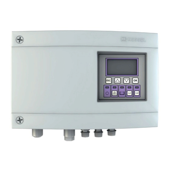
Allgemeines 1.4.1 Display und Bedienfeld, Anzeigen Position Bezeichnung Funktion, Beschreibung Display Menüstruktur siehe 5.6 LED Betriebsbereit – Leuchten: Betrieb mit Netzspannung – Aus: Betrieb mit Batteriespannung (wenn „Netzausfall“ im Display angezeigt wird) LED Alarm Blinken: Alarmzustand LED Niveau/Level Leuchtet bei Rückstau LED Rückstauklappe – Leuchten: Rückstauklappe geschlossen –...
Sicherheit Sicherheit Bestimmungsgemäße Verwendung Das Schaltgerät ist ausschließlich für die Steuerung von Rückstaupumpanlagen für fäkalienfreies und fäkalienhaltiges* Abwasser zu verwenden. Ein Einsatz des Schaltgeräts in explosionsgefährdeter Umgebung ist unzulässig. Alle nicht durch eine ausdrückliche und schriftliche Freigabe des Herstellers erfolgten –...
Montage Montage Schaltgerät befestigen Sicherstellen, dass das Schaltgerät während den Montagearbeiten von der Spannungsversorgung getrennt ist. • Montageposition wählen, dabei folgendes sicherstellen: – Eine Schutzkontaktsteckdose befindet sich in unmittelbarer Nähe zum Schaltgeräte. – Die Anschlusskabel von Abwasserpumpe, Rückstauklappe und Niveausensoren können fachgerecht installiert und bis zum Schaltgerät geführt werden.
Erweiterung beiliegenden Anleitung beschrieben. Abb. [7] Steckverbindungen Anschlusskabel herstellen Gefahr durch falsch dimensionierte Anschlussleitungen. Der Pumpfix/Ecolift ist auschließlich für den Betrieb mit den mitgelieferten Anschlussleitungen (oder gleichwertig) vorgesehen. Im Zweifelsfall mit Hersteller / Lieferant Rücksprache nehmen. Achtung, Gefahr durch elektrischen Strom bei unbefugtem Öffnen eines Steckers während dem Betrieb durch z.B.
Seite 11
Stecker Motorantrieb der Rückstauklappe am Anschluss <2> anschließen • Stecker Rückstausensor (optische Sonde, zur Ermittlung des Alarm- Pegelstandes, in Richtung Abwasserkanal) am Anschluss <3> anschließen Zuordnung der Anschlusskabel siehe Abb. [10] (Pumpfix) bzw. Abb. [11] (Ecolift) Abb. [9] 2017/01 11 / 168...
Montage 3.3.1 Potentialfreien Kontakt anschließen (Option) • Adernendhülsen (Länge 8 mm) an den Kabelenden anbringen • Anschlusskabel gemäß Anschlussplan an der Klemmleiste befestigen. Dazu mit einem geeigneten Schraubendreher die jeweilige Kabelklemme <3> gegen den Federdruck hinuntergedrückt halten, bis das Kabelende hineingesteckt ist •...
Beschreibung des Bedienschemas siehe 5.6 Bei der Erstinbetriebnahme werden folgende Eingaben erwartet: 1. Sprache für die Displayanzeige 2. Datum / Uhrzeit 3. Produkttyp – Einstellungen, je nach Produkttyp (Auswahl Pumpfix F oder Ecolift) 4. Wartungsintervall Initialisierung durchführen • Schaltgerät mit Netzspannung versorgen, ein Selbsttest mit folgenden Schritten wird durchgeführt –...
Einen Alarmzustand (Alarm-LED blinkt) herstellen und damit sicherstellen, dass das Signal am potentialfreien Kontakt erkennbar ist. Hierzu Netzspannung abschalten, Alarmzustand ist hergestellt, Funktion kann überprüft werden SMS-Alarmierung aktivieren • Verfahren, wie in der diesem Zubehör (Kessel TeleControl Modem) beiliegenden Anleitung beschrieben Funktionsprüfung durchführen • Sicherstellen, dass im Display keine Fehlermeldung anliegt •...
Betrieb Betrieb Einschalten • Spannungsversorgung herstellen – Das Schaltgerät führt einen Selbsttest durch. – Im Display wird der in der Anlagenkonfiguration eingestellte Gerätetyp angezeigt. – Sofern kein Systemfehler, Alarm oder erhöhtes Abwasserniveau erkannt wurde - leuchtet die grüne Betriebsbereit-LED <19> (siehe Abb. [4]). – Das Schaltgerät ist betriebsbereit. Wenn längere Zeit keine Eingabe erfolgt, wird die Displaybeleuchtung nach 1 Min. ausgeschaltet. Ausschalten •...
Betrieb Alarmmeldung bei Netzausfall Ein Netzausfall wird durch die Batterieversorgung des Schaltgerätes erkannt und wie folgt dargestellt: – Akustischer Alarm (kurzes Signal, ca. alle 20 Sekunden) – Displayanzeige: Netzausfall – Entsprechend dem Fehlerbild blinken (im gleichen Intervall wie der akustische Alarm) eine oder mehrere LED‘s: PUMP PUMP...
Betrieb Handbetrieb allgemein Im Handbetrieb kann folgendes durchgeführt werden: – Abwasserpumpe EIN- / AUS – Rückstauklappe in Position AUF / ZU bewegen 5.5.1 Handbetrieb Abwasserpumpe 1. Handbetrieb aktivieren • Taste Pumpe <26> betätigen, die LED Pumpe <23> blinkt, Nun findet kein automatisches Einschalten der Abwasserpumpe mehr statt.
Betrieb Rückstauklappe im Handbetrieb öffnen Nur möglich, wenn die Rückstauklappe im Handbetrieb geschlossen wurde und kein Rückstau anliegt (LED Rückstauklappe <22> leuchtet). • Taste Rückstauklappe <25> betätigen, die Rückstauklappe wird von der Position ZU in die Position AUF bewegt. Während der Positionsänderung blinkt die LED Rückstauklappe <22>. Die Rückstauklappe ist geöffnet, wenn die LED Rückstauklappe <22>...
USB Anschluss herausführen Damit der auf der Platine befindliche USB-Anschluss ohne ein Öffnen des Gehäuses zugängig wird, kann eine USB-Gehäusebuchse mit Kabel und Stecker zum Einbau in das Gehäuse des Schaltgerätes bei KESSEL bestellt werden (siehe 1.2.2). 2017/01 23 / 168...
Fehlersuche Fehlersuche Achtung, Beim Öffnen des Schaltgerätegehäuses besteht Gefahr vor elektrischer Spannung. Arbeiten an elektrischen Bauteilen dürfen nur von Fachpersonal (Siehe 2.2) durchgeführt werden. Fehler Ursache Abstellmaßnahme Batteriefehler Batterie fehlt, ist defekt oder Spannung zu gering Netzstecker ziehen, Batterien anschließen, ggf. durch neue Batterien ersetzen.
Stromausfall nicht mehr funktionsfähig sind. Beispielsweise, wenn die Steuerung während der Bauphase installiert wird, aber noch keine durchgehende Netzversorgung vorliegt. In diesem Fall wäre der Pumpfix/Ecolift durch die Batterieversorgung betriebsbereit; die Batterie würde aber vollkommen entleert werden.
Führend in Entwässerung Privater Wohnungsbau ohne Kanalanbindung 1 2 3 4 1 2 3 4 Öffentlicher Bau z.B. Krankenhaus Öffentlicher Bau z.B. Freizeitanlagen 1 2 3 4 Gewerblicher Bau z.B. Hotel Gewerblicher Bau z.B. Industriebau 2 3 5 Gewerblicher Bau z.B.
Seite 29
INSTRUCTIONS FOR INSTALLATION, OPERATION AND MAINTENANCE KESSEL Pumpfix / Ecolift control unit Product advantages Plug&play connections Multi-line display, intuitive menu guidance Self-diagnosis system Maintenance interval with reminder USB interface Optional: GSM interface Installation Putting into operation Instructional briefing for the system was carried out by your specialist...
Seite 30
Table of contents General information Introduction and greeting ....................32 Product description, general ..................... 32 1.2.1 Type plate ......................... 33 1.2.2 Scope of delivery ......................33 General instructions on using these operating and maintenance instructions ....34 Assemblies, functional elements and connections ............34 1.4.1 Display and control panel ....................
Seite 31
5.5.2 Backwater flap manual mode ................... 46 Operating menu ........................ 47 Adapting cable lengths, software update Shortening or lengthening the pump/sensor connection cable ......... 50 Update and reading out data .................... 50 6.2.1 Read out data ........................51 6.2.2 Carry out software update ....................51 6.2.3 Read in parameters ......................
Product description, general The Pumpfix / Ecolift control unit (hereinafter referred to as the control unit) is the control unit for a KESSEL backwater pumping station with integrated pump and a backwater flap locked by a motor. The level sensor switching signals for the wastewater level are processed electronically.
General information General instructions on using these operating and maintenance instructions Symbols and legends used <1> Reference in the text to a legend number in an illustration Reference to an illustration • Working step List Italics Italic case design: Reference to a section / item in the control menu CAUTION: Warns of a risk to persons and material.
General information 1.4.1 Display and control panel Position Designation Function, description Display Menu structure, see 5.6 LED Ready for – Lights up: operation with mains voltage operation – Off: operation with battery voltage (if “power outage” appears in the display) LED Alarm Flashing: alarm status Level LED...
Safety Safety Correct use The control unit may only be used to control backwater valves of the type FKA for wastewater with or without sewage. The control unit must not be used in a potentially explosive environment. – conversions or attachments –...
Installation Installation Fastening the control unit Make sure that the control unit is disconnected from the power supply during installation work. • Select the mounting position making sure that: – there is a safety socket in the direct vicinity of the control units. –...
[7] Connecting the plug-type connections to the connecting cable Danger through incorrectly dimensioned connection cables. The Pumpfix/Ecolift is only designed for operation with the enclosed connection cables (or equivalent). If in doubt, consult the manufacturer / supplier. Beware of the risk through electric current if a plug is opened without authorisation during operation e.g.
Seite 39
• Connect the backwater sensor’s plug (optical probe to determine the alarm level in the direction of the wastewater duct) to the connection <3> Assignment of the connecting cable, see Fig. [10] (Pumpfix) or Fig. [11] (Ecolift) fig. [9] 2017/01...
Seite 40
Installation Pumpfix version fig. [10] Ecolift version fig. [11] 40 / 168 2017/01...
Installation 3.3.1 Connect the potential-free contact (Option) • Fit end sleeves (length 8 mm) to the ends of the cables • Attach connecting cable to the terminal strip acc. to the circuit diagram To do so, keep the relevant cable terminal <3> pressed down against the spring pressure with a suitable screwdriver until the end of the cable has been inserted •...
During commissioning, the following input is expected: 1. Language for the display 2. Date / Time 3. Product type – Settings, depending on the type of product (Pumpfix F or Ecolift) 4. Maintenance interval Carrying out initialisation • Supply the control unit with mains voltage, a self-test is performed with the following steps –...
To do so, switch off the mains voltage, alarm status is established, the function can be checked Activate SMS alerting • Proceed as described in the instructions included with this accessory (Kessel TeleControl Modem). Carrying out a functional check • Make sure that no error message is pending in the display •...
Operation Operation Switching on • Set up the voltage supply – The control unit performs a self-test. – The display shows the device type set in the system configuration. – If no system error, alarm or increased wastewater level is detected - the green ready for operation LED comes on <19>...
Operation Alarm message in the event of a power outage A power outage is detected by the control unit’s battery supply and shown as follows: – Acoustic alarm (short signal, approx. every 20 seconds) – Display: Power outage – One or more LEDs flash according to the fault pattern (at the same interval as the acoustic alarm) FLAP PUMP FLAP...
Operation Manual mode, general The following can be carried out in the manual mode: – Wastewater pump ON / OFF – Move the backwater flap to the OPEN / CLOSED position 5.5.1 Wastewater pump manual mode 1. Activate manual operation •...
Operation Opening the backwater flap in the manual mode Only possible if the backwater flap has been closed in the manual mode and there is no backwater (backwater flap LED <22> is on). • Press the backwater flap key <25>, the backwater flap is moved from the CLOSED to the OPEN position. The backwater flap LED <22>...
Seite 48
Operation System info Information Hours of operation 1.1.1 Total running time 1.1.2 Power outage 1.1.3 Energy usage 1.1.4 Backwater phase 1.1.5 Backwater occurrences 1.1.6 Operating cycles flap 1.1.7 Run time pump 1.1.8 Op. cycle pump 1.1.9 Overvoltage 1.1.10 Undervoltage Log book Control type 1.4.1 Maintenance date...
Seite 49
Operation 2.6.4 12 months 2.6.5 Manual maintenance Settings Parameters 3.1.1 SDS Self diagnosis system 3.1.2 On delay flap 3.1.3 Post run time flap 3.1.4 Max. current flap 3.1.5 Switch-on delay pump 3.1.6 Run-on time pump 3.1.7 Max. current pump 3.1.8 Min.
Adapting cable lengths, software update Adapting cable lengths, software update Caution, risk caused by electric current! The conversions described below may only be carried out by authorised and qualified electricians (see 2.2, Staff selection and qualification). Shortening or lengthening the pump/sensor connection cable Extensions to be ordered (length 10m) –...
Routing the USB connection out To make the USB socket on the board accessible without the housing having to be opened, a USB housing socket with cable and connector for installation in the control unit housing can be ordered from KESSEL (see 1.2.2).
Troubleshooting Troubleshooting Caution, risk of electrical voltage when the control unit housing is opened. Work on electrical components may only be carried out by specialist staff (page 2.2). Error possible cause Remedial measure Battery fault Battery is missing or faulty Remove the mains plug, connect batteries, replace by new batteries if necessary.
This is particularly important during the construction phase, for example, when the control unit is installed but not yet continuously supplied with mains current. In this case, the Pumpfix/Ecolift is ready for operation thanks to battery operation, but the battery is not discharged complete...
Leading in Drainage Private homes without public sewage connection 1 2 3 4 1 2 3 4 Public buildings (e.g. hospital) Public buildings (e.g. leisure facility) 1 2 3 4 Commercial buildings (e.g. hotel) Commercial buildings (e.g. industrial / manu- facturing facilities) 2 3 5 Commercial buildings...
Seite 57
INSTRUCTIONS DE POSE, D‘UTILISATION ET DE MAINTENANCE Gestionnaire KESSEL Pumpfix / Ecolift Avantages du produit Prêt au raccordement Écran d‘affichage à plusieurs lignes, arborescence intuitive du menu Système d‘autodiagnostic Intervalle de maintenance avec fonction mémoire Port USB Option : interface GSM L‘installation...
Seite 58
Sommaire Généralités Introduction et accueil ....................... 60 Description générale du produit ..................60 1.2.1 Plaque signalétique ......................61 1.2.2 Détail de livraison ......................61 Informations d‘ordre général concernant ces instructions d‘utilisation et de maintenance ........................62 Composants, éléments fonctionnels et raccordements ............ 62 1.4.1 Écran et panneau de commande, affichages ..............
Seite 59
5.5.1 Commande manuelle de la pompe d‘assainissement ............74 5.5.2 Commande manuelle du clapet anti-retour ............... 74 Menu de commande ......................75 Adaptation de la longueur des câbles, mise à jour du logiciel Raccourcissement ou rallongement du câble de raccordement de la pompe / du détecteur ........................
Chère cliente, Cher client, Nous vous félicitons de votre achat d‘un produit KESSEL. Ce produit sera certainement en mesure de répondre à toutes vos attentes. Nous vous souhaitons une mise en place sans faille et réussie. Nous tentons de maintenir un niveau de qualité aussi élevé que possible de nos produits et avons évidemment besoin de votre collaboration.
Généralités Informations d‘ordre général concernant ces instructions d‘utilisation et de maintenance Pictogrammes et légendes utilisés <1> Information dans le texte attirant l‘attention sur un numéro de légende dans une figure Renvoi à une figure • Étape opératoire Énumération Italique caractères en italique : renvoi à une section / point dans le menu de commande ATTENTION : avertit d‘un danger corporel et matériel.
Généralités 1.4.1 Écran et panneau de commande, affichages Position Désignation Fonction, description Écran Arborescence du menu, voir 5.6 Diode d’état – Brillent : en service sous tension de réseau opérationnel – Éteintes : service sous tension de batterie (si l’écran affiche « Panne de secteur ») Diode d’alarme Clignotement : état d’alarme...
Sécurité Sécurité Utilisation conforme à l‘usage prévu Le gestionnaire est exclusivement destiné à commander des postes de relevage (DIN EN 12050, partie 1-3) et des clapets anti-retours avec pompe pour eaux grises et eaux-vannes*. L‘utilisation du gestionnaire dans des zones à risque d‘explosion est interdite. Il faut savoir, à...
Montage Montage Fixation du gestionnaire S’assurer que le gestionnaire a été coupé de l’alimentation en tension pendant les travaux de montage. • Choisir l‘emplacement prévu au montage en veillant aux points suivants : – Proximité directe du gestionnaire d‘une prise secteur avec terre. –...
Ill. [7] Raccordement des connecteurs et câbles Risque dû au dimensionnement erroné des conduites de raccordement. Le Pumpfix/Ecolift est exclusivement prévu pour une utilisation avec les conduites de raccordement fournies (ou des conduites équivalentes). Demander conseil au fabricant / fournisseur en cas de doute.
Seite 67
Raccorder le connecteur du capteur de reflux (sonde optique de détection du niveau d’alarme dans la direction de la canalisation des eaux d‘égout) au raccordement <3> Affectation des câbles de raccordement, voir Fig. [10] (Pumpfix) ou Fig. [11] (Ecolift) Ill. [9]...
Seite 68
Montage Variante Pumpfix Ill. [10] Variante Ecolift Ill. [11] 68 / 168 2017/01...
Montage 3.3.1 Raccordement du contact sans potentiel (Option) • Monter les manchons de bout pour torons (longueur de 8 mm) aux extrémités des câbles • Fixer le câble de raccordement suivant le schéma de raccordement à la réglette à bornes. Pour ce faire, se servir d‘un tournevis à fente approprié...
La première mise en service impose de procéder aux saisies suivantes : 1. Langue de l’écran d‘affichage 2. Date / Heure 3. Type du produit – Configurations suivant le type du produit (Pumpfix F /Ecolift) 4. Intervalle de maintenance Mise en œuvre de l‘initialisation •...
Pour se faire, couper la tension d‘alimentation qui a pour effet d’établir l’état d’alarme ; la fonction est vérifiable Activation de l’alarme par textos • Procéder comme décrit aux instructions jointes à cet accessoire (Kessel TeleControl Modem) Contrôle fonctionnel • Vérifier l‘absence d’un message d‘erreur à l’écran •...
Service Service Mise en circuit • Établir l’alimentation en tension – Le gestionnaire exécute un autodiagnostic. – L‘écran affiche le type d‘appareil paramétré dans la configuration du système. – Si le système fonctionne correctement sans défaut, la diode verte qui signale que l’appareil est en ordre de marche <19>...
Service Message d‘alarme en cas de panne de secteur Une panne de secteur est identifiée par l’alimentation de la batterie du gestionnaire et signalée comme suit : – Alarme acoustique (bref signal à intervalles d’env. 20 secondes) – Affichage de l‘écran : Panne de secteur –...
Service Commande manuelle en général La manœuvre suivante est possible par commande manuelle : – Pompe d‘assainissement MARCHE / ARRÊT – Déplacement du clapet anti-retour à la position OUVERTE / FERMÉE 5.5.1 Commande manuelle de la pompe d‘assainissement 1. Activation de la commande manuelle •...
Service Ouverture du clapet anti-retour par commande manuelle Manœuvre uniquement possible si le clapet anti-retour a été fermé par une commande manuelle et en l’absence d’un reflux (la diode du clapet anti-retour <22> brille). • Appuyer sur la touche du clapet anti-retour <25> ; le clapet anti-retour est déplacé de la position FERMÉE sur la position OUVERTE.
Service Arborescence du menu 0. Info système 1.1.1 1. Informations Heures de service Durée totale 1.1.2 Panne de secteur 1.1.3 Consommation d‘énergie 1.1.4 Durée de la mise en charge 1.1.5 Nombre de mises en charge 1.1.6 Cycles du battant 1.1.7 Durée de marche de la pompe 1.1.8 Point de commutation de la pompe...
Seite 77
Service 2.6.3 6 mois 2.6.4 12 mois 2.6.5 Maintenance manuelle 3.1.1 Configurations Paramètres Système d‘autodiagnostic SDS 3.1.2 Temporisation de mise en circuit du battant 3.1.3 Durée de fonctionnement par inertie du battant 3.1.4 Courant Courant du battant 3.1.5 Temporisation de mise en circuit de la pompe 3.1.6 Fonctionnement par inertie de la pompe 3.1.7...
Adaptation de la longueur des câbles, mise à jour du logiciel Adaptation de la longueur des câbles, mise à jour du logiciel Attention au danger lié au courant électrique ! Les rééquipements décrits ci-après demeurent réservés au domaine de compétence exclusif d’électriciens agréés (voir 2.2 Sélection et qualification du personnel). Raccourcissement ou rallongement du câble de raccordement de la pompe / du détecteur Rallonges disponibles (longueur de 10 m) –...
Afin que le port USB situé sur la platine soit aussi accessible sans l‘ouverture du boîtier, il est possible de commander un boîtier à douille USB, équipé d‘un câble et d‘un connecteur à intégrer dans le boîtier du gestionnaire chez KESSEL (voir 1.2.2). 2017/01...
Aide au diagnostic Aide au diagnostic Attention : danger de tension électrique en ouvrant le boîtier du gestionnaire. Les travaux sur les composants électriques demeurent réservés au domaine de compétence d‘électriciens qualifiés (voir 2.2). Affichage des pannes Cause Mesure d’arrêt Panne de batterie La batterie manque ou est défectueuse Retirer la fiche de secteur, connecter les batteries, si...
Déclaration de conformité Déclaration de conformité 82 / 168 2017/01...
Seite 83
Leader en solution d’assainissement Construction de logements privés sans raccordement au réseau d’assainissement public 1 2 3 4 1 2 3 4 Construction de logements Construction publique, par privés sans raccordement au exemple aménagement de loisirs réseau d’assainissement public 1 2 3 4 Construction industrielle 2 3 5...
Seite 84
ISTRUZIONI PER L‘INSTALLAZIONE, IL FUNZIONAMENTO E LA MANUTENZIONE Quadro elettrico KESSEL Pumpfix / Ecolift Vantaggi del prodotto Collegamenti pronti per l’uso Visualizzazione display a più righe, guida a menu intuitiva Sistema di auto- diagnostica Intervallo di manutenzione con avviso Interfaccia USB Opzionale: un‘interfaccia...
Seite 85
Indice Informazioni generali Introduzione e saluto ......................87 Descrizione del prodotto, in generale ................87 1.2.1 Targhetta ........................... 88 1.2.2 In dotazione ........................88 Indicazioni generali sulle presenti istruzioni per l’uso e la manutenzione ......89 Gruppi costruttivi, elementi funzionali e collegamenti ............89 1.4.1 Display e quadro di comando, visualizzazioni ..............
Seite 86
5.5.2 Modalità di funzionamento manuale clapet antiriflusso ............ 101 Menu di comando ......................102 Adattamento lunghezza cavi, aggiornamento software Accorciamento o allungamento del cavo di collegamento della pompa/sensore ..... 105 Aggiornamento e lettura dei dati ..................105 6.2.1 Lettura dati ........................106 6.2.2 Esecuzione dell’aggiornamento del software ..............
Ha delle domande? Saremo felici di ricevere le sue richieste. Descrizione del prodotto, in generale Il quadro elettrico Pumpfix / Ecolift (di seguito quadro elettrico) costituisce il comando di una valvola di non ritorno KESSEL con sistema di pompaggio, pompa integrata e clapet antiriflusso con chiusura motorizzata. I segnali di commutazione dei sensori delle acque di scarico vengono elaborati elettronicamente.
Materiale di fissaggio Mascherina per la realizzazione dei fori optional Generatore esterno di segnali (cod.art. 20162) Presa USB (cod.art. 28785) Modem di telecomando Kessel (cod.art. 28792) Codice di abilitazione per contatto a potenziale zero (cod.art. fig. [2] 80077) 88 / 168...
Informazioni generali Indicazioni generali sulle presenti istruzioni per l’uso e la manutenzione Simboli utilizzati e legenda <1> Riferimento nel testo ad un numero di legenda in un‘immagine Riferimento ad una figura • Passo di lavoro Numerazione Corsivo Scritta in corsivo: riferimento a una sezione / un punto nel menu di comando PRUDENZA: avverte circa un pericolo per le persone ed il materiale.
Informazioni generali 1.4.1 Display e quadro di comando, visualizzazioni Posizione Denominazione Funzione, descrizione Display Per la struttura del menu vedi 5.6 LED Prontezza al – Acceso: funzionamento con tensione di rete funzionamento – Spento: funzionamento con tensione della batteria (se sul display viene visualizzato „Guasto alla rete elettrica“) LED Allarme Lampeggiante: condizione di allarme...
Sicurezza Sicurezza Uso conforme alla destinazione Il quadro elettrico si deve utilizzare esclusivamente per comandare valvole di non ritorno con sistema di pompaggio per acque di scarico contenenti sostanze fecali o meno. Un impiego del quadro elettrico negli ambienti a rischio di esplosione non è ammesso. In assenza di un‘autorizzazione espressa e in forma scritta da parte del produttore, –...
Montaggio Montaggio Fissare il quadro elettrico Accertare che il quadro elettrico sia separato dall’alimentazione di tensione durante i lavori di montaggio. • Scegliere la posizione di montaggio accertando che: – Una presa con contatto di terra si trovi nelle immediate vicinanze del quadro elettrico.
[7] Esecuzione collegamenti a spina cavo di collegamento Pericolo a causa del dimensionamento errato dei condotti di collegamento. Il Pumpfix/Ecolift è destinato esclusivamente al funzionamento con le condotte di collegamento in dotazione (o analoghe). In caso di dubbio contattare il produttore / fornitore.
Seite 94
Collegare il connettore del sensore di ristagno (sonda ottica per il rilevamento del livello di allarme, in diretto canale acque di scarico) con il collegamento <3> Per l‘assegnazione dei cavi di collegamento, vedi fig. [10] (Pumpfix) o Figura [11] (Ecolift) fig. [9]...
Montaggio 3.3.1 Collegamento del contatto a potenziale zero (Opzionale) • Applicare i capicorda (lunghezza di 8 mm) alle estremità dei cavi. • Fissare il cavo di collegamento come indicato sullo scheda di collegamento accanto alla morsettiera. A tale fine, tenere premuto il rispettivo morsetto per cavo <3>...
Al momento della prima messa in funzione vengono richieste le seguenti immissioni: 1. lingua di visualizzazione del display 2. Data / Ora 3. Tipo di prodotto – Impostazioni a seconda del tipo di prodotto (Pumpfix F/Ecolift) 4. Intervallo di manutenzione Esecuzione dell‘inizializzazione •...
Opzionale: accertarsi che quanto segue funzioni correttamente • Contatto a potenziale zero • Allarme SMS (modem di telecomando Kessel) • Generatore di segnali esterno Quando tutti i punti rilevanti sono stati eseguiti, il quadro elettrico è pronto a funzionare 98 / 168...
Funzionamento Funzionamento Accensione • Inserire la tensione di alimentazione – Il quadro elettrico esegue l‘autotest. – Sul display viene indicato il tipo di apparecchio impostato nella configurazione dell’impianto. – Il LED verde di prontezza al funzionamento <19> (vedere figura [4]) si illumina se non sono stati identificati errori di sistema.
Funzionamento Segnalazione di allarme in caso di guasto della rete elettrica Un eventuale blackout viene rilevato dall‘alimentazione a batteria del quadro elettrico e indicato come segue: – Allarme acustico (breve segnale, all‘incirca ogni 20 secondi) – Display: Guasto alla rete elettrica –...
Funzionamento Funzionamento manuale generale In modalità di funzionamento manuale si può eseguire quanto segue: – Pompa di scarico acqua ON/OFF – portare il clapet antiriflusso in posizione Aperto/Chiuso 5.5.1 Modalità manuale pompa di scarico acqua 1. Attivazione del funzionamento manuale •...
Funzionamento Aprire il clapet antiriflusso in modalità di funzionamento manuale Possibile solo se il clapet antiriflusso era stato chiuso in modalità di funzionamento manuale e non c’è alcun ristagno (LED Clapet antiriflusso <22> acceso). • Azionare il tasto Clapet antiriflusso <25>, il clapet antiriflusso si porta dalla posizione Chiuso alla posizione Aperto.
Funzionamento Struttura del menu Info di sistema 1.1.1 Informazioni Ore di funzionamento Tempo di funzionamento complessivo 1.1.2 Guasto alla rete elettrica 1.1.3 Consumo energetico 1.1.4 Tempo del ristagno 1.1.5 Numero di ristagni 1.1.6 di commutazione max della cerniera 1.1.7 Tempo di funzionamento della pompa 1.1.8 Tens.
Seite 104
Funzionamento 2.6.2 3 mesi 2.6.3 6 mesi 2.6.4 12 mesi 2.6.5 Manutenzione manuale Impostazioni Parametri 3.1.1 Sistema di auto-diagnostica SDS 3.1.2 Ritardo di accensione della cerniera 3.1.3 Durata di funzionamento dopo lo spegnimento della cerniera 3.1.4 Corrente max della cerniera 3.1.5 Ritardo di accensione pompa 3.1.6...
Adattamento lunghezza cavi, aggiornamento software Adattamento lunghezza cavi, aggiornamento software Attenzione, pericolo causato dalla corrente elettrica! I riallestimenti di seguito descritti devono essere eseguiti esclusivamente da personale elettrico autorizzato (vedi 2.2, Scelta e qualifica del personale). Accorciamento o allungamento del cavo di collegamento della pompa/sensore Prolunghe ordinabili (lunghezza 10 m) –...
Per fare in modo che il collegamento USB presente sul circuito stampato sia accessibile senza dover aprire l‘alloggiamento è possibile ordinare presso KESSEL una presa USB per l‘alloggiamento con cavo e connettore per l‘installazione nell‘alloggiamento del quadro elettrico (vedi 1.2.2).
Ricerca di errori Ricerca di errori Attenzione! Quando si apre l‘alloggiamento del quadro elettrico si rischia di subire folgorazioni per la tensione elettrica presente. I lavori agli elementi elettrici devono essere eseguiti solo da personale specializzato (vedere 2.2). Anomalie Causa Rimedio Anomalia batteria Batteria mancante o difettosa...
Seite 108
Ricerca di errori Anomalia sonda IInizializzazione: linea controllo Staccare la spina, disattivare la batteria; controllare se la linea di “Sonda” non collegata, interrotta controllo è collegata correttamente e non è interrotta; eventualmente o polarità invertita Durante il sostituire la sonda funzionamento: linea di controllo “Sonda”...
Per esempio, se il comando viene installato durante la fase di costruzione, ma non esiste ancora alcuna alimentazione di rete costante. In questo caso l’Pumpfix/Ecolift sarebbe pronto al funzionamento grazie all’alimentazione a batteria, ma le batterie verrebbero scaricate completamente.
Dichiarazione di conformità Dichiarazione di conformità 110 / 168 2017/01...
Seite 111
Leader del drenaggio Edilizia residenziale privata senza collegamento alla fogna 1 2 3 4 1 2 3 4 Edilizia pubblica per es. Ospedale Edilizia pubblica per es. Impianti ricreativi 1 2 3 4 Edilizia commerciale per es. Albergo Edilizia commerciale per es.
Seite 112
HANDLEIDING VOOR DE INBOUW, HET GEBRUIK EN HET ONDERHOUD KESSEL-besturingskast Pumpfix / Ecolift Productvoordelen Direct aansluitbare aansluitingen Display-indicatie over verschillende regels, intuïtieve menubesturing Zelfdiagnosesysteem Onderhoudsinterval met herinnering USB-interface Optioneel GSM-interface Installatie Inbedrijfstelling Instructie van de installatie werd uitgevoerd door uw gespecialiseerd...
Seite 113
Inhoudsopgave Algemeen Inleiding en begroeting ..................... 115 Productomschrijving, algemeen ..................115 1.2.1 Typeplaatje ........................116 1.2.2 Leveringsomvang ......................116 Algemene instructies bij deze gebruiks- en onderhoudshandleiding ........ 117 Modules, functie-elementen en aansluitingen ..............117 1.4.1 Display en besturingspaneel, indicaties ................118 Veiligheid Voorgeschreven gebruik ....................
Hebt u vragen? Wij zien ernaar uit dat u contact opneemt. Productomschrijving, algemeen De besturingskast Pumpfix / Ecolift (hierna besturingskast genoemd) vormt de besturing van een KESSEL- terugstuwpompinstallatie met geïntegreerde pomp en een terugstuwklep met motorische vergrendeling. De schakelsignalen van de niveausensoren voor het afvalwaterpeil worden elektronisch verwerkt. Als niveausensoren worden optische sonden gebruikt.
Bedrijfs- en onderhoudshandleiding Aansluitschema, in het deksel van de omkasting van de besturingskast Bevestigingsmateriaal Boorsjabloon Optioneel Externe signaalgenerator (art. nr. 20162) USB-behuizingsbus (art. nr. 28785) Kessel TeleControl modem (art.nr. 28792) Vrijschakelcode voor potentiaalvrij contact (art.nr. 80077) Afb. [2] 116 / 168 2017/01...
Algemeen Algemene instructies bij deze gebruiks- en onderhoudshandleiding Gebruikte symbolen en legenda <1> Verwijzing in de tekst naar een legendanummer op een afbeelding Referentie naar een afbeelding • Productiestap Opsomming Cursief Cursieve letterweergave: Referentie naar een paragraaf/punt in het besturingsmenu LET OP: Waarschuwt tegen gevaar voor personen en materiaal.
Algemeen 1.4.1 Display en besturingspaneel, indicaties Positie Benaming Functie, beschrijving Display Menustructuur zie 5.6 LED bedrijfsklaar – Branden Werking met netspanning – Uit: Werking met batterijspanning (als op het display „stroomuitval“ wordt aangegeven) LED alarm Knipperen: Alarmtoestand LED niveau/level Brandt bij opstuwing LED terugstuwklep – Branden Terugstuwklep gesloten – Knipperen: Terugstuwklep wordt bewogen –...
Voorgeschreven gebruik De besturingskast mag uitsluitend worden gebruikt voor de besturing van terugstuwbeveiligingen van het type Pumpfix/Ecolift voor fecaliënvrij en fecaliënhoudend afvalwater Het is niet toegestaan de besturingskast in een omgeving met explosiegevaar te gebruiken. Alle niet door een expliciete en schriftelijke vrijgave van de fabrikant uitgevoerde –...
Montage Montage Besturingskast bevestigen Waarborgen dat de besturingskast tijdens de montagewerkzaamheden losgekoppeld is van de spanningsvoeding. • Montagepositie kiezen, daarbij moet het onderstaande gegarandeerd zijn: – in de onmiddellijke nabijheid is een geaard stopcontact aanwezig. – De aansluitkabel van de afvalwaterpomp, de terugstuwklep en niveausensoren de kunnen volgens voorschrift geïnstalleerd en naar de besturingskast geleid worden.
Afb. [7] Insteekverbindingen aansluitkabel maken Gevaar door aansluitleidingen in de verkeerde maat. De Pumpfix/Ecolift is uitsluitend voor werking met de meegeleverde (of gelijkwaardige) aansluitleidingen bedoeld. Ingeval van twijfel contact met de fabrikant/ leverancier opnemen. Attentie, gevaar door elektrische stroom bij onbevoegd openen van een stekker tijdens het bedrijf door bv.
Seite 122
• Stekker terugstuwsensor (optische sonde, voor het vaststellen van de alarmniveaustand, in de richting van het afvalwaterriool) op aansluiting <3> aansluiten Indeling van de aansluitkabels zie afb. [10] (Pumpfix) c.q. afb. [11] (Ecolift) Afb. [9] 122 / 168 2017/01...
Montage 3.3.1 Potentiaalvrij contact aansluiten (Optie) • Adereindhulzen (lengte 8 mm) op de kabeluiteinden aanbrengen • De aansluitkabels conform het aansluitschema op de klemstrip bevestigen. Daarvoor de betreffende kabelklem met een geschikte schroevendraaier <3> tegen de veerdruk in omlaag gedrukt houden tot het kabeluiteinde is ingestoken •...
Beschrijving van het bedieningsschema zie 5.6 Bij de eerste inbedrijfstelling wordt de volgende invoer verwacht: 1. Taal voor de display-indicatie 2. Datum / tijd 3. Producttype – Instellingen, afhankelijk van producttype (Pumpfix or Ecolift) 4. Onderhoudsinterval Initialisatie uitvoeren • Besturingskast voorzien van netspanning, er wordt een zelftest met de volgende stappen uitgevoerd –...
In de handmodus de afvalwaterpomp inschakelen (zie 5.5.1) Optioneel: Waarborgen dat het volgende op de voorgeschreven wijze functioneert • Potentiaalvrij contact • SMS-alarmering (Kessel TeleControl Modem) • Externe signaalsensor Als alle relevante punten zijn uitgevoerd, is de besturingskast bedrijfsklaar. 126 / 168...
Bedrijf Bedrijf Inschakelen • Spanningsvoeding in orde maken – De besturingskast voert een zelftest uit. – Op het display wordt het in de installatieconfiguratie ingestelde apparaattype aangegeven. – Voor zover geen systeemfout, alarm of verhoogd afvalwaterniveau herkend werd - brandt de groene bedrijfsgereed-LED <19> (zie afb. [4]). – De besturingskast is bedrijfsklaar. Indien gedurende langere tijd niets wordt ingevoerd, wordt de displayverlichting na 1 minuut uitgeschakeld.
Bedrijf Alarmmelding bij stroomuitval Een stroomuitval wordt herkend door de batterijvoeding van de besturingskast en als volgt weergegeven: – Akoestisch alarm (kort signaal, ong. om de 20 seconden) – Display-indicatie Netuitval – Overeenkomstig het storingsbeeld knipperen (met dezelfde interval als het akoestische alarm) een of meer LED’s: PUMP PUMP...
Bedrijf Handmodus algemeen In de handmodus kan het volgende worden uitgevoerd: – Afvalwaterpomp AAN- / UIT – Terugstuwklep naar positie OPEN / DICHT bewegen 5.5.1 Handmodus afvalwaterpomp 1. Handmatige modus activeren • Toets pomp <26> gebruiken, de LED pomp <23> knippert, nu wordt de afvalwaterpomp niet meer automatisch ingeschakeld.
Bedrijf Terugstuwklep in de handmodus openen Uitsluitend mogelijk als de terugstuwklep in de handmodus is gesloten en er geen terugstuwing is (LED terugstuwklep <22> brandt). • Toets terugstuwklep <25> gebruiken, de terugstuwklep wordt vanuit de positie DICHT naar de positie OPEN bewogen.
Kabellengten aanpassen, software update Kabellengten aanpassen, software update Attentie, gevaar door elektrische stroom! Hieronder beschreven modificaties mogen uitsluitend door geautoriseerde gediplomeerde elektriciens worden uitgevoerd (zie 2.2, Personeelskeuze en -kwalificatie). Netsnoer pomp / sonden inkorten of verlengen Bestelbare verlengingen (lengte 10 m) – Art.nr. 80889 sonde – Art.nr. 80890 motor – Art. nr. 80891 pomp De maximale kabellengte van 30 m mag niet worden overschreden. Als een aansluitkabel wordt ingekort, moet het leggen van de draden gebeuren zoals afgebeeld: Motorstekker –...
USB-aansluiting naar buiten voeren Om toegang te krijgen tot de op de printplaat aanwezige USB-aansluiting zonder de behuizing te openen kan bij KESSEL een USB-behuizingsbus met kabel en stekker voor inbouw in de behuizing van de besturingskast (zie 1.2.2). 134 / 168...
Opsporen van storingen Opsporen van storingen Attentie, bij het openen van de behuizing van de besturingskast bestaat gevaar voor elektrische spanning. Werkzaamheden aan elektrische componenten mogen uitsluitend door geschoold personeel (zie 2.2) worden uitgevoerd. Indicatie Oorzaak Uitschakelmaatregel Batterijstoring Batterij ontbreekt of is defect Netstekker uittrekken, batterijen aansluiten, evtl.
Seite 136
Opsporen van storingen Klepstoring Klep kan bij de inbedrijfstelling, c.q. door Netstekker uittrekken, batterij deactiveren; Staufix-deksel de toets „Controleren“ niet volledig worden openen, blokkering verwijderen en installatie opnieuw in gesloten, d.w.z. de klep wordt door een gebruik nemen voorwerp in de opstuwingsafsluiter geblokkeerd Advies: Vakbedrijf informeren - Foutieve hendelpositie bij dekselmontage Opstuwing is herkend.
Bijvoorbeeld wanneer de besturing tijdens de bouwfase wordt geïnstalleerd, maar doorlopende netvoeding nog niet aanwezig is. In dit geval zou de Pumpfix/Ecolift door de batterijvoeding gereed voor bedrijf zijn; de batterij zou echter volkomen geleegd worden.
Seite 140
INSTRUKCJA MONTAŻU, OBSŁUGI I KONSERWACJI Urządzenie sterujące Pumpfix/Ecolift KESSEL Zalety produktu Gotowe do podłączenia przyłącza Wielowierszowy wyświetlacz, intuicyjne prowadzenie po menu System samodiagnozy Przypomnienie o terminie konserwacji Złącze USB Opcjonalnie: Złącze GSM Instalacja Uruchomienie Szkolenie zostały przeprowadzone przez zakład specjalistyczny: Imię...
Seite 141
Spis treści Informacje ogólne Wprowadzenie i powitanie ....................143 Ogólny opis produktu ......................143 1.2.1 Tabliczka znamionowa ...................... 144 1.2.2 Zakres dostawy ......................... 144 Informacje ogólne dotyczące niniejszej instrukcji obsługi i konserwacji ......145 Podzespoły, elementy funkcyjne i przyłącza ..............145 1.4.1 Wyświetlacz i panel sterowniczy, wskazania ..............
Seite 142
5.5.2 Tryb ręczny klapy zwrotnej ....................157 Menu obsługi ........................158 Dopasowanie długości kabli, aktualizacja oprogramowania Skrócenie lub przedłużenie kabla przyłączeniowego pompy/czujnika ......161 Aktualizacja i odczyt danych ..................... 161 6.2.1 Odczyt danych ........................162 6.2.2 Aktualizacja oprogramowania ................... 162 6.2.3 Wczytanie parametrów .....................
Mają Państwo pytania? Prosimy o kontakt. Ogólny opis produktu Urządzenie sterujące Pumpfix/Ecolift (w dalszej części nazywane urządzeniem sterującym) służy do sterowania automatycznym zaworem zwrotnym KESSEL ze zintegrowaną pompą i klapą zwrotną z motoryczną blokadą. Sygnały przełączające czujników poziomu ścieków przetwarzane są elektronicznie. Czujnikami poziomu są...
Informacje ogólne Informacje ogólne dotyczące niniejszej instrukcji obsługi i konserwacji Stosowane symbole i legendy <1> Wskazówka w treści odnosząca się do numeru legendy na rysunku Odniesienie do rysunku • Krok roboczy Wyliczenie Tekst pisany kursywą: Odniesienie do fragmentu/punktu w menu sterowania Kursywa OSTROŻNIE: Ostrzeżenie przed zagrożeniem dla osób lub rzeczy.
Informacje ogólne 1.4.1 Wyświetlacz i panel sterowniczy, wskazania Pozycja Nazwa Funkcja, opis Wyświetlacz Struktura menu patrz 5.6 Dioda LED gotowości – Świeci się: Eksploatacja z napięciem sieciowym do pracy – Wyłączona: Eksploatacja z napięciem bateryjnym (na wyświetlaczu wyświetla się „Awaria sieci“) Dioda LED alarmu Miga: Stan alarmowy Dioda LED poziomu...
Bezpieczeństwo Bezpieczeństwo Zastosowanie zgodnie z przeznaczeniem Urządzenie sterujące jest przeznaczone wyłącznie do sterowania i automatycznymi zaworami zwrotnymi ze zintegrowaną pompą do ścieków zawierających fekalia* i bez fekaliów. Użycie urządzenia sterującego w otoczeniu zagrożonym wybuchem jest niedozwolone. Wszelkie bez wyraźnej i pisemnej zgody producenta –...
Montaż Montaż Mocowanie urządzenia sterującego Upewnić się, że urządzenie sterujące jest na czas prac montażowych odłączone od zasilania napięciem. • Wybrać pozycję montażową, upewniając się przy tym, że: – Gniazdo wtykowe z zestykiem ochronnym znajduje się w bezpośrednim pobliżu urządzenia sterującego. –...
Rys. [7] Podłączenie kabli przyłączeniowych Zagrożenie wskutek źle dobranych wielkości przewodów przyłączeniowych. Urządzenie sterujące Pumpfix/ Ecolift jest przewidziane do użytku wyłącznie z dostarczonymi przewodami przyłączeniowymi (lub równoważnymi). W razie wątpliwości skontaktować się z producentem/dostawcą. Uwaga, niebezpieczeństwo porażenia prądem elektrycznym w przypadku nieupoważnionego otwarcia wtyczki podczas eksploatacji, np.
Seite 150
Podłączyć wtyczkę napędu silnikowego klapy zwrotnej do przyłącza <2>. • Podłączyć wtyczkę czujnika spiętrzenia (sonda optyczna do wykrywania stanu alarmowego poziomu, w kierunku kanału ściekowego) do przyłącza <3>. Przyporządkowanie kabli przyłączeniowych patrz rys. [10] (Pumpfix) lub rys. [11] (Ecolift) Rys. [9] 150 / 168 2017/01...
Montaż 3.3.1 Podłączenie kontaktu bezpotencjałowego (Opcja) • Umocować na końcach kabli tulejki końcowe żył (długość 8 mm). • Przymocować kabel przyłączeniowy zgodnie ze schematem połączeń w listwie zaciskowej. W tym celu odsunąć śrubokrętem odpowiedni zacisk kabla <3> pokonując przy tym opór sprężyny i wcisnąć...
Opis schematu obsługi patrz 5.6 Podczas uruchomienia po raz pierwszy należy wprowadzić następujące dane: 1. Język wskazań na wyświetlaczu 2. Data/godzina 3. Typ produktu – Ustawienia, zależnie od typu produktu (Pumpfix/Ecolift) 4. Częstotliwość konserwacji Przeprowadzenie inicjalizacji • Podłączyć urządzenie sterujące do zasilania sieciowego, wykonywany jest auto test w następującej kolejności:...
W tym celu wyłączyć zasilanie, stan alarmowy jest utworzony, można sprawdzić funkcję. Aktywacja funkcji wysyłania wiadomości SMS z alarmem • Postępować przy tym w sposób opisany w załączonej instrukcji dla tego rozszerzenia (Kessel TeleControl Modem). Wykonanie kontroli działania •...
Eksploatacja Eksploatacja Włączenie • Podłączenie zasilania – Urządzenie sterujące przeprowadza auto test. – Na wyświetlaczu wyświetla się typ urządzenia ustawiony w konfiguracji. – Jeżeli nie został rozpoznany żaden błąd systemu, alarm lub podwyższony poziom ścieków, zapala się zielona dioda LED gotowości do pracy <19> (patrz rys. [4]). –...
Eksploatacja Komunikat „Konieczna konserwacja“,można wyłączyć przyciskiem alarmu <20>, jeżeli wprowadzony został automatyczny termin konserwacji (menu 2.6). Jeżeli wybrany i ustawiony został „Ręczny termin automatyczny tkonserwacji“, konieczne jest wprowadzenie następnego terminu konserwacji. Komunikat o alarmie podczas awarii sieci Awaria sieci zostaje rozpoznana przez zasilanie bateryjne urządzenia sterującego i przedstawiona w następujący sposób: –...
Eksploatacja Ogólne informacje o trybie ręcznym W trybie ręcznym można wykonać następujące czynności: – Włączyć/wyłączyć pompę ściekową – Ustawić klapę zwrotną w pozycji zamkniętej/otwartej 5.5.1 Tryb ręczny pompy ściekowej 1. Aktywowanie trybu ręcznego • Nacisnąć przycisk pompy <26>, miga dioda LED pompy <23>, pompa ściekowa nie jest już...
Eksploatacja Otwarcie klapy zwrotnej w trybie ręcznym Możliwe tylko wtedy, gdy klapa zwrotna została zamknięta w trybie ręcznym i nie występuje spiętrzenie (świeci się dioda LED klapy zwrotnej <22>). • Nacisnąć przycisk klapy zwrotnej <25>, klapa zwrotna zmienia pozycję z zamkniętej na otwartą. Podczas zmiany pozycji miga dioda LED klapy zwrotnej <22>.
Eksploatacja Struktura menu Informacja o systemie 1.1.1 Informacje Godziny robocze Łączny czas pracy 1.1.2 Awaria sieci 1.1.3 Zużycie energii 1.1.4 Czas spiętrzenia 1.1.5 Liczba spiętrzeń 1.1.6 Cykle łączeniowe klapy 1.1.7 Czas pracy pompy 1.1.8 Cykle łączeniowe pompy 1.1.9 Za wysokie napięcie 1.1.10 Za niskie napięcie Dziennik zdarzeń...
Seite 160
Eksploatacja 2.6.3 6 miesięcy 2.6.4 12 miesięcy 2.6.5 Konserwacja ręczna 3.1.1 Ustawienia Parametry System samodiagnozy SDS 3.1.2 Opóźnienie włączenia klapy 3.1.3 Czas dobiegu klapy 3.1.4 Maksymalny prąd klapy 3.1.5 Opóźnienie włączenia pompy 3.1.6 Czas dobiegu pompy 3.1.7 Maksymalny prąd pompy 3.1.8 Minimalny prąd pompy 3.1.9...
Dopasowanie długości kabli, aktualizacja oprogramowania Dopasowanie długości kabli, aktualizacja oprogramowania Uwaga! Niebezpieczeństwo porażenia prądem elektrycznym! Poniżej opisane rozszerzenia może wykonywać wyłącznie autoryzowany specjalista elektryk (patrz 2.2. Wybór i kwalifikacje personelu). Skrócenie lub przedłużenie kabla przyłączeniowego pompy/czujnika Dostępne przedłużenia (długość 10 m) –...
Wybrać Wczytanie parametrów, podać hasło i potwierdzić przyciskiem OK, wczytywanie wykonywanie jest automatycznie. Wyprowadzenie portu USB Jeżeli port USB ma być dostępny bez konieczności otwarcia obudowy, można zamówić w firmie KESSEL gniazdo USB z kablem i wtyczką do zabudowy w obudowie urządzenia sterującego (patrz 1.2.2). 162 / 168...
Wyszukiwanie błędów Wyszukiwanie błędów Uwaga! Podczas otwierania obudowy urządzenia sterującego istnieje niebezpieczeństwo porażenia prądem elektrycznym. Prace przy podzespołach elektrycznych może wykonywać wyłącznie personel specjalistyczny (patrz 2.2). Wyświetlanie błędu Przyczyna Działanie Błąd baterii Brak baterii lub uszkodzona Odłączyć wtyczkę sieciową, podłączyć baterie, w razie potrzeby wymienić.
Seite 164
Wyszukiwanie błędów Błąd klapy Klapa nie może przy uruchomieniu względnie Wyciągnąć wtyczkę z gniazda, dezaktywować baterie; za pomocą przycisku kontrolnego zostać otworzyć pokrywę zaworu Staufix usunąć przyczynę całkowicie otwarta czyli klapa jest zablokowana zablokowania i ponownie uruchomić urządzenie przez przedmiot w zaworze zwrotnym Zalecenie: skontaktować...
, by w razie braku prądu funkcja nie przestała działać . Przykładowo, jeśli sterowanie zostanie zainstalowane podczas fazy budowlanej, ale urządzenie nie zostanie jeszcze podłączone do napięcia w sieci . W takim przypadku urządzenie Pumpfix/Ecolift będzie gotowe do pracy dzięki zasilaniu bateryjnemu, baterie zostaną jednak całkiem wyczerpane...
Seite 168
Rückseite_PL_Layout 1 25.06.13 16:13 Seite 1 Wiodący producent systemów odwadniania Budownictwo mieszkaniowe bez podłączenia do kanalizacji 1 2 3 4 5 1 2 3 4 5 Budynki użyteczności Budowle ogólnodostępne publicznej, np. szpitale np. obiekty rekreacyjne Działalność gospodarcza np. hotele Budownictwo przemysłowe 2 3 5...