Werbung
Verfügbare Sprachen
Verfügbare Sprachen
Quicklinks
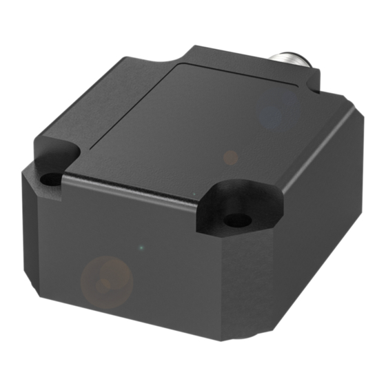
MEMS Inclination Sensors with Analog Output
BSI R65K0-X _-M _ _ _ _-S115
EU Directive 2004/108/EC (EMC Directive) and EMC Law
Generic Standards: EN 61000-6-4 (Emissions), EN 61000-6-2 (Interference Immunity)
Emissions testing: Radio interference emissions EN 55011 Group 1, Class A and B
Downloading the user's guide
The user's guide can also be found on the Internet
in other languages at www.balluff.com.
Intended use
The inclination sensor was built to monitor the angle of
inclination in one or two axes.
Inclination sensors are installed for use in, for example,
machines, equipment, devices and systems whose inclina-
tion position has to be determined precisely and set
exactly via connected PLC controllers and motors.
Flawless function in accordance with the specifications in
the technical data is ensured only when using original
Balluff accessories, and use of any other components will
void the warranty.
Typical applications are, for example, detecting the inclina-
tion of operating tables, solar panels, and excavators.
Modifications to the sensor or non-approved use are not
permitted and will result in loss of warranty and void any
liability claims against the manufacturer.
Safety notes
Before commissioning, read the user's guide
carefully!
These sensors must not be used in applications
in which the safety of persons is dependent on
the function of the device (not a safety compo-
nent according to EU Machinery Directive).
Installation and startup are to be performed by trained
technical personnel only.
The operator is responsible for ensuring that local safety
regulations are observed.
In particular, the operator must take measures to ensure
that a defect in the measuring system will not result in
hazards to persons or equipment.
If defects or non-clearable faults in the sensor occur, take it
out of service and secure against unauthorized use.
1
English
Validity
These instructions describe the structure, function, installa-
tion and operation of the following inclination sensors:
Type
Axes
Output
BSI R65K0-XB-MX_ _ _ _-S115
1
Current
(different measuring ranges)
BSI R65K0-XA-MX_ _ _ _-S115
1
Voltage
(different measuring ranges)
BSI R65K0-XB-MY_ _ _ _-S115
2
Current
(different measuring ranges)
BSI R65K0-XA-MY_ _ _ _-S115
2
Voltage
(different measuring ranges)
Dimensions
Electrical connections
Caution!
Only establish the electrical connection in a dee-
nergized state.
Pin 1-axis
2-axis
connection
connection
1
Floating
Y output signal
2
Supply +
3
Internal interface
4
Internal interface
5
GND
6
Centering device (calibration)
7
Output signal
X output signal
8
Shield
Connection notes:
–
Only use shielded cables!
MEMS Inclination Sensors with Analog Output
BSI R65K0-X _-M _ _ _ _-S115
Installation
Caution!
Note the alignment of the inclination axis or
axes during installation.
–
Always install the inclination sensors in a deenergized
state.
–
The measurement values can be inexact for equipment
that vibrates heavily. Ensure sufficient vibration isola-
tion.
–
In highly accelerated systems, the sensor does not
provide exact measurement values.
–
Make sure that the installation surface is clean and
level.
–
For installation, the end of the connector should always
be straight.
Mounting the sensor with 1 measurement axis
The inclination sensor is mounted vertically onto the
object.
To obtain precise measured values, the reference surface
on the underside of the sensor has to be perfectly vertical.
Deviations from this horizontal position can be compensa-
ted by calibrating using pin 6.
Secure on the side of the object:
Screw the sensor to the object using
4 screws (max. thread diameter of 5 mm).
Mounting the sensor with 2 measurement axes
The inclination sensor is mounted horizontally onto the
object.
To obtain precise measured values, the reference surface
on the underside of the sensor has to be perfectly level.
Deviations from this vertical position can be compensated
by calibrating using pin 6.
Secure to the object:
Screw the sensor to the object
using 4 screws (max. thread
diameter of 5 mm).
www.balluff.com
Inclination axis of the sensor with 1 measurement axis
The sensor's counting direction using a measurement axis
depends on its inclination alignment, for example:
–
Clockwise (+X direction):
from 0° to 180°
or
from 0° to 45°, for example
–
Counterclockwise (–X direction):
from 0° to –180°
or
from 0° to –45°, for example
Ordering
Types with 1 measurement
Measure-
code
axis
ment
angle
BSI0015
BSI R65K0-XB-MXP360-S115
±180°
BSI001E
BSI R65K0-XB-MXS015-S115
±15°
BSI0018
BSI R65K0-XB-MXS030-S115
±30°
BSI0019
BSI R65K0-XB-MXS045-S115
±45°
BSI001A
BSI R65K0-XB-MXS090-S115
±90°
BSI0016
BSI R65K0-XA-MXP360-S115
±180°
BSI001C
BSI R65K0-XA-MXS015-S115
±15°
BSI0017
BSI R65K0-XA-MXS030-S115
±30°
BSI001F
BSI R65K0-XA-MXS045-S115
±45°
BSI0005
BSI R65K0-XA-MXS090-S115
±90°
Centering function (calibration)
At the factory, the inclination sensors are calibrated to the
perfect vertical alignment (1-axis) and perfect horizontal
alignment (2-axis). The maximum deviation is 0.2°.
If the current installation position deviates from these
perfect vertical and horizontal alignments, the sensor can
be centered.
Procedure
1. Bring the object into the zero position using the
installed sensor.
2. Supply the sensor with current and center it within 1
minute as described below:
3. Connect the centering input (pin 6) with the ground for
at least 0.5 seconds.
4. Then, disconnect it. The centering input must remain
free during normal operation.
English
2
Werbung

Verwandte Anleitungen für Balluff BSI R65K0-XB-MXS030-S115


Inhaltszusammenfassung für Balluff BSI R65K0-XB-MXS030-S115
- Seite 1 Screw the sensor to the object using BSI0015 BSI R65K0-XB-MXP360-S115 ±180° Balluff accessories, and use of any other components will 4 screws (max. thread diameter of 5 mm). void the warranty. BSI001E BSI R65K0-XB-MXS015-S115 ±15°...
- Seite 2 Electronic Equipment). Equipment should be disposed of separately from household waste! Degree of protection IP 67 as per IEC 60529 Enclosure Type as per UL 50/50E 1 Balluff GmbH Schurwaldstraße 9 73765 Neuhausen a.d.F. Germany Phone +49 7158 173-0 Fax +49 7158 5010 balluff@balluff.de...
- Seite 3 Achten Sie darauf, dass die Montagefläche sauber und BSI R65K0-XB-MY_ _ _ _-S115 Strom Diese Betriebsanleitung erhalten Sie im Internet eben ist. (unterschiedliche Messbereiche) unter www.balluff.com auch in anderen Sprachen. – Zur Installation nur gerade Steckverbinder verwenden. BSI R65K0-XA-MY_ _ _ _-S115 Spannung (unterschiedliche Messbereiche) Montage des Sensors mit 1 Messachse Bestimmungsgemäße Verwendung...
- Seite 4 95% nicht betauend Altgeräte) zu entsorgen. Altgeräte dürfen nicht in den Hausmüll gelangen! Schutzart nach IEC 60529 IP 67 Enclosure Type nach UL 50/50E 1 Balluff GmbH Schurwaldstraße 9 73765 Neuhausen a.d.F. Deutschland Tel. +49 7158 173-0 Fax +49 7158 5010 balluff@balluff.de...