Bpt XO/200 Installationsanleitung
Quicklinks
COM
DL3
P6
P6
I3
P5
P5
DL2
P4
I2
P3
P3
DL1
P2
I1
P1
P1
M1
06.2002/2405-4500
DL3
P6
I3
P5
DL2
P4
I2
P3
DL1
P2
I1
P1
ON
DL3
SW3
I3
DL2
OFF
SW2
P4
I2
DL1
SW1
P2
I1
XO/200
ISTRUZIONI PER
I
L'INSTALLAZIONE
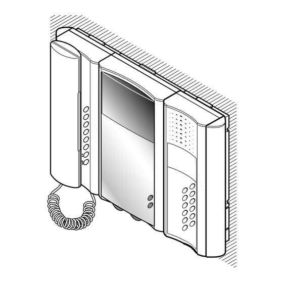
MODULO SERVIZI XO/200
Questo modulo, abbinato al moni-
tor o al citofono serie Exedra, per-
mette di installare in un impianto
dei servizi supplementari.
È munito dei seguenti comandi e
segnalazioni (fig. 1):
P1÷P6 6 pulsanti
I1÷I3
3 interruttori
DL1
led rosso
DL2
led verde
DL3
led giallo
Morsettiera M1 (fig. 2)
Per utilizzare i LED collegare DL1,
DL2 e DL3 ad una tensione com-
1
presa tra 11 e 18 Vcc e COM alla
massa di alimentazione.
I LED possono essere attivati dai
relativi pulsanti, con i ponticelli
SW1, SW2 e SW3 posizionati in
OFF, oppure esternamente con i
ponticelli in posizione ON.
Caratteristiche tecniche
• Potere interruzione pulsanti e
interruttori: 24 V 100 mA.
• Tensione attivazione LED: da
+11 a +18 Vcc.
• Temperatura di funzionamento:
da 0 °C a +35 °C.
Fissaggio del modulo servizi al
modulo monitor o al modulo
citofono
Murare la scatola incasso (da tre
moduli o tonda Ø 65 mm) a filo
muro e ad una altezza adeguata
all'utente.
Unire i supporti tramite i due giun-
ti (fig. 4) ed inserire i due copriforo
rettangolari sui lati esterni (fig. 3).
Fissare i supporti sul muro utiliz-
zando le viti ed i tasselli in dota-
zione (fig. 5, 6 e 7).
Inserire la base sul supporto
XKP/85 ed innestarla al supporto
stesso con un movimento verso il
basso (fig. 8).
Bloccare la base tramite la vite in
dotazione (fig. 8).
Scrivere i dati desiderati sul cartel-
lino portanomi ed inserirlo nella
sede del mobile (fig. 9).
Montare il mobile del modulo
citofono (fig. 10-11).
Dopo aver montato i vari moduli,
2
applicare i due fianchi (fig. 12).
BPT SpA
30020 Cinto Caomaggiore
Venezia - Italy
GB INSTALLATION
INSTRUCTIONS
SERVICE MODULE XO/200
Using this module, teamed with
the Exedra-series monitor or hand-
set, supplementary services can
be added to an installation.
It is equipped with the following
controls and warnings, figure 1:
P1-P6
6 push-buttons
I1-I3
3 switches
DL1
red LED
DL2
green LED
DL3
yellow LED
Terminal block M1 (fig. 2)
To use the LEDs, connect DL1,
DL2 and DL3 to a voltage supply
in the range 11 to 18V DC, and
COM to the power supply earth.
LEDs can be activated with the rele-
vant buttons, with jumpers SW1,
SW2 and SW3 set to OFF, or exter-
nally with the jumpers set to ON.
Technical features
• Max load to push-buttons and
switches: 24 V 100 mA.
• Voltage range for activating
LED: +11 to +18 VDC.
• Working temperature range:
from 0 °C to +35 °C.
Fastening service module to
monitor module or handset
module
Fit the embedding box (three-
module or round Ø 65 mm ver-
sion) in the wall so that it is flush
and at a suitable height for users.
Use the two couplings (fig. 4) to
join the mountings together and
insert the two rectangular hole
plugs on the outer sides (fig. 3).
Fasten the mountings on the wall
using the screws and screw
anchors supplied (fig. 5, 6 and 7).
Insert the base on the XKP/85
mounting and insert it on the actual
support by pushing downwards,
figure 8.
Secure the base in place using the
screw supplied figure 8. Write
desired data on the name card
and insert it in the relevant slot on
the unit (fig. 9). Fit the handset
module housing figure 10-11.
Once you have fitted the various
modules, apply the two side
panels (fig. 12).
1

Verwandte Anleitungen für Bpt XO/200


Inhaltszusammenfassung für Bpt XO/200
- Seite 1 30020 Cinto Caomaggiore Venezia - Italy ISTRUZIONI PER GB INSTALLATION L’INSTALLAZIONE INSTRUCTIONS SERVICE MODULE XO/200 MODULO SERVIZI XO/200 Using this module, teamed with Questo modulo, abbinato al moni- the Exedra-series monitor or hand- tor o al citofono serie Exedra, per-...
- Seite 2 INSTALLATIONS- INSTRUCTIONS POUR L’INSTALLATION ANLEITUNG SERVICEMODUL XO/200 MODULE SERVICES XO/200 Durch die Kombination dieses Intégré au moniteur ou au portier Moduls mit dem Monitor oder der électronique série Exedra, ce Sprechgarnitur der Serie Exedra module permet d’installer des ser- kann die Anlage mit Zusatzdien- vices supplémentaires.
- Seite 3 INSTRUÇÕES INSTRUCCIONES PARA LA INSTALACION PARA A INSTALAÇÃO MÓDULO SERVICIOS XO/200 MÓDULO SERVIÇOS XO/200 Este módulo, combinado con el Este módulo, unido ao monitor ou monitor o el portero electrónico ao telefone série Exedra, permite serie Exedra, permite incorporar de instalar num equipamento ser- servicios suplementarios en una viços suplementares.