NZR PowerCount+ Bedienungsanleitung
Elektrizitätszähler
Quicklinks
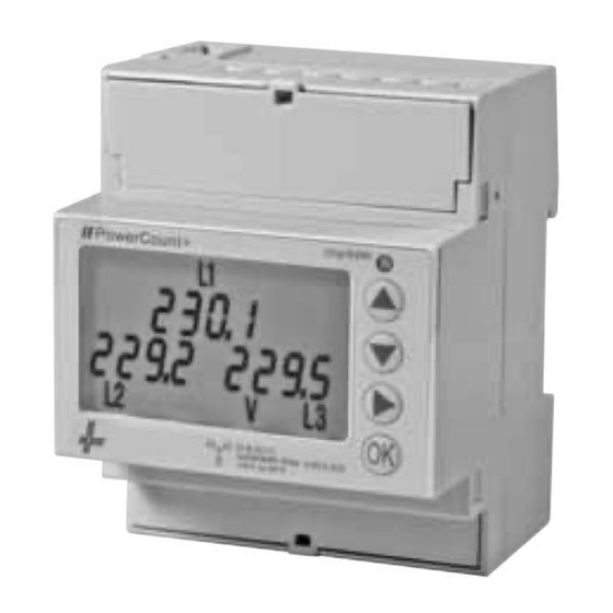
PowerCount+
Elektrizitätszähler
Digitaler 3-Phasen
mit Stromwandleranschluss (.../1A oder .../5A)
Bedienungsanleitung
Die PowerCount+ Zähler zeigen wichtige Messgrößen wie I, U, PF, F, TDH%
und die Leistung aller Phasen sowie die Wirkenergie für Lieferung und Bezug.
Zwei verschiedene Sekundärwandler
können für den Einsatzbereich gewählt
werden:
• von 0,01 - 1 (1.2) A für Wandler .../1 A
• von 0,05 - 5 (6) A für Wandler .../5 A
• Alle PowerCount+ haben 2 Tarife und
seitliche IR Kommunikationsanschluß
Die eingebaute Kommunikation unterscheidet sich in:
Kode
Modell
Kommunikation
51010205
PowerCount+
2 S0 Impulse-Ausgänge
51010305
PowerCount+ Modbus
eingebauter RS-485 Modbus RTU
51010405
PowerCount+ M-Bus
eingebauter M-Bus (1 Lastgröße)
WARNUNG
Die Installation muss von einer Elektrofachkraft oder unter deren Leitung und
Aufsicht durchgeführt und geprüft werden.
Bei Arbeiten am Messgerät, Netzspannung abschalten!
Einstellung der Messwerte
Measurements pages
• Für alle Seiten die nicht Energien angeben, ist die Tarifangabe auf den
Betriebsablauf bezogen.
• In case of Energy pages, the tariff of the accumulated Energy is indicated
In the other pages, the running tariff is indicated.
Phasenströme - Rückbeleuchtung aus
Line currents Backlight OFF
Jede Taste drücken
OK
Any Key pushing
Phasenströme - Rückbeleuchtung ein
Line currents Backlight ON
I-L
V-L/N
V-L/L
PF-L
P-L
Q-L
S-L
L F (Hz)
I - 0
I THD%
V THD%
L kWh
Bezug T1
import T1
L kWh
Bezug T2
import T2
L kWh
Abgabe T1
export T1
DEUTSCH
PowerCount+
Three-phase Digital
CT connected (.../5 A or .../1 A)
Operating instructions
The PowerCount+ provides all relevant measures for the evaluation of
an electrical network: I, U, PF, F, TDH% and Power (displayed for
each phase) and 3-phase
imported and exported active Energies.
• Two possible currents ranges: 0.01-1 (1.2) in
case of .../1 A external CTs, or 0.05-5 (6) in
case of .../5 A external CTs
• All models are three phase digital
PowerCount+ with 2 tariffs and with IR lateral
communication available.
The built-in communication depends of the model:
Code
Model
Communication
51010205
PowerCount+
2 S0 Pulse outputs
51010305
PowerCount+ Modbus
Built in RS-485 Modbus RTU
51010405
PowerCount+ M-Bus
Built in M-Bus (1 unit Load)
RISK OF ELECTROCUTION, BURNS OR EXPLOSION
This device must be installed and maintained ONLY by qualified
and duly authorized personnel.
During its installation, be sure there is no voltage applied
L kWh
Abgabe T2
export T2
Zurück zu den Seiten
Back to page
I-L
Aus beliebiger Seite die Taste "
" für 3 Sek. drücken um zu den
Parameterseiten zu gelangen.
Whicherer the measurement page push "
parameter pages
Parameter - Eingabe
(jede Änderung erfordert mit Password Eingabe)
Parameters Set-up
(a password is required to modify their values)
Alle Seiten können mit den Tasten
"
"
und
"
Aus jeder Seite mit
3 Sek. Tastenbetätigung, zurück in die Seiten der Messwerte.
"
"
"
"
Available Parameter Pages (push
or
In any page, push
key for more that 3 seconds to go back to measure pages.
Siehe den Paragraph für
Password Beschreibung
Die Stromwandler mit sekundärer.
mit Wicklung .../5 A haben einen
Einsatzbereich von 5 und 10.000 A
mit Wicklung .../1 A haben einen
Einsatzbereich von 1 und 2000 A
See the dedicated paragraph for Password description.
External CTs primary nominal current. Value selectable between 5 and 10.000 in
case CTs secondary nominal current is 5 A, and between 1 and 2000 in case CTs
secondary nominal current is 1 A.
Stromwandler wählbar mit
sekundären Wicklung .../1 A oder .../5 A
External CTs secondary nominal current.
Value selectable between 1 A and 5 A
Diese Seite ist nur für Kode PowerCount+ S0 zustimmend
These 3 pages are available in PowerCount+ S0 model only
Anzahl der Ausgang Impulse / kWh bezogen
auf Iprim des Stromwandler. Der kleinste
Wert ist 1 Impuls/kWh. Der höchste hängt
vom gewählten Stromwandler und der
OK
Impulslänge ab. (Siehe nachstehend).
Number of S0 output pulses per kWh
(referred to CTs primary currents).
The minimum value is 1 pulse/kWh.
The maximum depends on selected external
CT ratio and on Pulse Length
(see note below).
Die Impulslänge ist zwischen
30 und 100 msek wählbar.
OK
S0 ON time pulse length (in milliseconds).
Value selectable between 30 and 100 msec.
Bemerkung:
Die höchstmögliche Impulsanzahl pro kWh (Impulskonstante) die der Zähler über
den S0-Ausgang zulässt ist mit dem Stromwandler und der Einschaltzeit der
Impulse abhängig. Hieraus ergibt sich:
zum Beispiel, wenn Sie in Ihrer Anlage einen Wandler mit einem Verhältnis
10.000/5 = 200 und eine Einschaltzeit von 70 msek. wählen wird die
Impulskonstante sein:
Sie können jederzeit da Wandlerverhältnis und die Einschaltzeit ändern, sollte die
Impulsfrequenz für Ihren Zweck zu hoch sein. Das Ergebnis ist automatisch auf den
Grenzwert bezogen.
Note:
The maximun number of pulses per kWh (Pulse constant) that the meter can
generate through S0 ouputs is limited by the CT ratio and by the ON time of the
pulse. The relationship is:
For example, if in your installation you need a CT ratio of 10.000/5 = 200
and a ON pulse time of 70 ms, the maximum Pulse constant that you can select is:
You can always modify the CT ratio and the pulse ON time as you prefer; in case the
Pulse Constant is too high for your selections, it is automatically adjusted to the
maxmum allowed value.
S0 - Impuls Ausgangswahl
Es sind 3 verschiedene outputs auf die
Leistung Iprim des Wandler bezogen.
1) S01 hinsichtlich der Bezugswirkleistung.
OK
S02 hinsichtlich der Abgabewirkleistung
(wie hier abgebildet).
2) S01 hinsichtlich der Bezugswirkleistung
S02 hinsichtlich der Bezugsblindleistung
(Act-React sichtbar am Display)
3) S01 hinsichtlich der Bezugswirkleistung T1
S02 hinsichtlich der Bezugswirkleistung T2
(Am Display mit T1 bzw. T2 gezeigt).
S0 pulse outputs mode selection.
There are 3 available choices (always referred to powers at primary)
1)S01 proportional to Imported Active Power, S02 proportional to
Exported Active Power (as in the case showh here)
2)S01 proportional to Imported Active Power, S02 proportional to Imported Reactive
Power (Act-React on the display)
3)S01 proportional to Imported Active Power under Tariff T1, S02 proportional to
Imported Active Power under Tariff T1 (tar 1-tar 2 on the display).
ENGLISH
Diese Seiten sind rein auf den Kode PowerCount+ Modbus
und Kode PowerCount+ M-Bus bezogen
These pages are available in models PowerCount+ Modbus
and PowerCount+ M-Bus
Diese 2 Seiten sind nur für PowerCount+ M-Bus zutreffend
These 2 pages are available in PowerCount+ M-Bus model only
Die Eingabe und Ablesung der sekundären Adresse ist auf 2 Seiten aufgeteilt.
Die ersten 4 Zahlen werden auf die erste Seite geschrieben, die restlichen auf die
folgende Seite. z.B. Die sekundäre kann lauten: 46750062.
.
M-Bus secondary address visualization and modification is splitted into 2 pages
(Most significant 4 digits and Least Significant 4 digits). In the following example,
the Secondary address = 46750062.
" key for 3 sec. to enter into
Diese 2 Seiten sind nur für PowerCount+ Modbus zutreffend
These 2 pages are available in PowerCount+ Modbus model only
"
durchgewählt werden.
to scroll pages).
Bemerkung:
Jede Kombination der Parität und Stop Bits ist wählbar;
Nach Vorlage Modbus sind nur die nachstehenden Kombinationen ratsam:
Even/1, Odd/1 und None/2.
Note:
any combination of Parity and Stop Bits are selectable; anyway, according to
Modbus recommendation, only the following 3 combinations are allowed:
Even/1, Odd/1 and None/2.
Bemerkung:
Die höchstmögliche Impulsanzahl pro kWh (Impulskonstante) die der Zähler über den
S0-Ausgang zulässt ist mit der Wahl des Stromwandler abhängig.
Hieraus ergibt sich:
zum Beispiel, wenn Sie in Ihrer Anlage einen Wandler mit einem Verhältnis
1000/5 = 200 wählen, wird die Impulskonstante sein:
Sie können jederzeit das Wandlerverhältnis ändern, sollte die Impulsfrequenz für
Ihren Zweck zu hoch sein. Das Ergebnis wird automatisch auf den Grenzwert
bezogen.
Note:
The maximum number of LED pulses per kWh (Pulse constant is limited by the CT).
The relationship is:
For example, if in your installation you need a CT ratio of 1000/5=200,
the maximum LED Pulse constant that you can select is:
You can always modify the CT ratio as you prefer; in case the Pulse Constant is too
high for your selection, it is automatically adjusted to the maximum allowed value.
Einstellung der Parameter mit Password geschärft (ON)
Parameter modification example
In beliebiger Parameterseite mit der Taste
Dies kann in folgender Weise erfolgen:
In any parameter page, push
"
possible if the Password is disabled; alternatively it is possible to introduce the
password in the following way:
Bus Adresse wählbar zwischen 1 und 247 für
Modbus und zwischen 0 bis 250
für M-Bus.
Bus address (selectable between 1 and 247
in case of Modbus and between 0 and 250
for M-Bus).
Die Übertragungsgeschwindigkeit ist für
Modbus wählbar in: 1200, 2400, 4800, 9600,
19200, 38400 und für M-Bus in: 300, 600,
1200, 2400, 4800 und 9600 Baud.
Communication baudate (selectable among
1200, 2400, 4800, 9600, 19200 and 38400
for Modbus; selectable among 300, 600,
1200, 2400, 4800 and 9600 Baud
for M-Bus).
Nach 60 Sek. Tasten Inaktivitat muß die Password erneut eingegeben werden.
After 60 sec. of inactivity reenter the password.
In gleicher Weise können auch andere Parameter geändert werden.
Die ersten vier Zahlen auf die erste Seite.
The same technique is applicable to modify the other parameters.
M-Bus Secondary Address: Upper 4 digits.
Für die Nullstellung der Energieregister wie folgt vorgehen.
Any value between 0000 and 9999 is
accepted.
To reset the energies, proceed in the following way.
Die restlichen Zahlen auf die zweite Seite
geschrieben.
M-Bus Secondary Address: Lower 4 digits.
Any value between 0000 and 9999 is
accepted.
Modbus Parität Wahl.
None, Old und Even Parity sind wählbar
(siehe nachstehend).
Modbus Parity Selection.
None, Odd and Even Parity choices are
available. (see the note below).
Anzeige bei Phasenausfall und falschen Phasensequenzanschluß
Modbus Anzahl der Stop Bits Wahl.
1 oder 2 Stop Bits sind wählbar
(siehe nachstehend).
Modbus Number of Stop Bits selection.
1 or 2 Stop bits are selectable.
(see the note below).
Anzahl des rmetrologischen roten LED
pro kWh (bezogen auf die Iprim Wicklung)
Der kleinste Impulsanzeige pro kWh ist 1;
die höchste ist von der Wahl des Wandlers
OK
(Iprim) abhängig.
Number of Metrological red LED pulses per
kWh (referred to CTs primary currents).
The minimum value is 1 pulse/kWh.
The maximum depends on selected external
CT (see note below).
724368
=
200 = 60
Kabel-Abisolierlänge und Max Drehmoment der Klemmenschraube
Cable stripping length and max terminal screw torque
Befehl zur Rücksetzung der Energiemeßstände
5 A Wandleranschluss Hauptklemmen
Schraubendreher PZ1
Energy Counters reset command
OK
5 A CT connection main terminals
Screw driver PZ1
Tarif-und Datenübertragungsklemmen
Schraubendreher Klinge 0.8x3.5 mm
Password geschärft (ON)
Password ungeschärft (OFF)
Tariff and communication terminals
Screw driver blade 0.8x3.5 mm
Password enabling/disabling.
OK
Password ON means: the password is enabled;
Password OFF means: the password is
disabled
OK
"
" können Änderungen erfolgen.
OK
" key to start modification. The modification is
OK
}
Beide Tasten gleichzeitig drücken >4 Sek.
Push Both >4 Sec.
OK
Löschen / Cancel
Bestätigen / Confirm
+
-
Löschen / Cancel
OK
Bestätigen / Confirm
Seitenwahl
Page selection
Energie Nullstellung / Energy Reset
OK
Mit der Taste
die Energieregister
aufrufen.
OK
Push
to ask for energies resetting.
OK
OK
Mit nochmaliger Drücken der
Taste die
Nullstellung aufrufen und sofort bestätigen
ansonsten nach 8 Sekunden geht der
gewünschte Befehl verloren.
OK
OK
Push
to confirm the Energy Counters
reset (all energy counters are zeroed).
Otherwise push
or wait for 8 seconds
without pushing any key to cancel the
command.
Phases Sequence Error Message
OK
Taste mehr als 4 Sek. drücken um den
Hinweis zu löschen.
OK
OK
By pushing
for more than 4 sec. the message
disappears.
Maße
Dimension
Plombierbare Klemmenabdeckungen
Sealable terminal covers
Zusätzliche Schnittstelle für Kommunikation
Connectable Communication Modules
1.5 Nm
14
0.5 Nm
9
NZR - 49196 Bad Laer (Germany)

Verwandte Anleitungen für NZR PowerCount+


Inhaltszusammenfassung für NZR PowerCount+
- Seite 1 2)S01 proportional to Imported Active Power, S02 proportional to Imported Reactive Power (Act-React on the display) 3)S01 proportional to Imported Active Power under Tariff T1, S02 proportional to NZR - 49196 Bad Laer (Germany) Imported Active Power under Tariff T1 (tar 1-tar 2 on the display).
- Seite 2 To be used only under the following conditions: • The load is 3 wires (no neutral) and there is no current leakage (l1 - l2 - l3 = 0) NZR - 49196 Bad Laer (Germany) • Only 3-phase measures (∑ Power and Energies) are meaningful.