Eckerle EE2000T1 Anleitung
Quicklinks
T1
EE2000
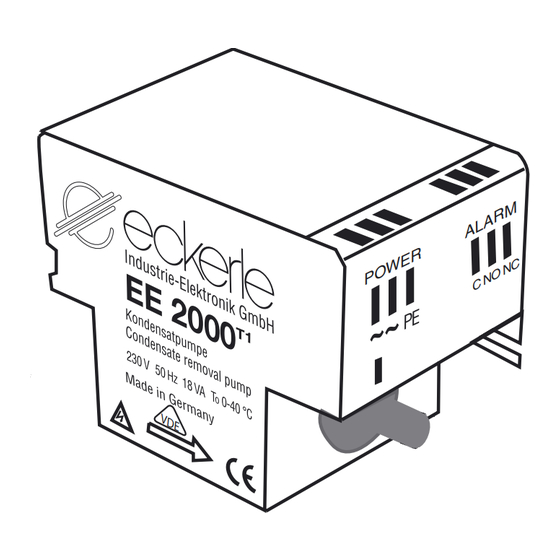
EE 2000T1
��
Kondensatförderpumpe
��
�������������������� ������
�
Condensate revolve pump
�
�
�
�
�
�
�
�
�
�
�
�
������������������� ������ ���
Pumpenmodul/
Potentialfreier Kontakt/
Pump unit
Alarm Potential free contact
NC
AUSGANG PHASE / Phase outlet
NO
EINGANG PHASE / Phase inlet
C
Anschluß Schwimmermodul/
Connection Detector
Unzulässige Einbaulage
Pompe de revelage de condensats
Mounting position to avoid
Position de montage
Pompa elevatrice di condensa
Posizione di montaggio da evitare
Te vermijden montage opstellingen
Kondens water pomp
LIEFERUMFANG / SCOPE OF SUPPLY
2x
� � � � � � � � � � � � � � � � � � � � � � � �
ZUBEHÖR / ACCESSORIES
Verlängerungskabel 3 m
Verlängerungskabel 5 m
Verlängerungskabel 10 m
Schlauch 100 m Rolle Innenø 6 mm x 1,5
��
Extension cable 3 m
��
Extension cable 5 m
Extension cable 10 m
��
Flexible piping ø 6 mm x 1,5 (100 m)
��
Bloc de détection de 3 m
Bloc de détection de 5 m
��
�
Bloc de détection de 10 m
Tube clair ø 6 mm x 1,5 (bobine 100 m)
Blocco di revelazione da 3 m
Blocco di revelazione da 5 m
Blocco di revelazione da 10 m
Condetto flessibile ø 6 mm x 1,5 (100 m)
Verlengkabel da 3 m
Verlengkabel 5 m
Verlengkabel 10 m
Soepele Afvoerslang ø 6 mm x 1,5 (100 m)
ERSATZTEILE / SPARE PARTS
Pumpenblock
Schwimmermodul
Pump unit
Detector
max. 23 mm
Alarm
max. 18 mm +/- 2
EIN/ON
max. 14 mm +/- 2
AUS/OFF
Gemessen ab Unterkante
Schwimmermodul / Specified from the
bottom surface
BKL Air Conditioner GmbH Hanns-Martin-Schleyer-Str. 30 a 47877 Willich - Münchheide II
Tel. 0 21 54 / 92 21 - 50 Fax 0 21 54 / 92 21 - 99 e-mail: bkl@bkl-klima.de internet www.bkl-klima.de
DEUTSCH
Die Kondensatpumpe EE 2000
Bestell-Nr. 22003
oder Wandgeräten integriert werden. Das Gerät besteht aus zwei Teilen: Pum-
Bestell-Nr. 22005
penblock und Schwimmermodul.
Bestell-Nr. 22010
Technische Daten:
Bestell-Nr. 22150
max. Fördermenge: 10 l/h
max. Saughöhe:
2,5 m
Leistung:
18 VA
Ref.-No. 22003
1. INBETRIEBNAHME
Ref.-No. 22005
Ref.-No. 22010
1.1 Elektrischer Anschluss
Ref.-No. 22150
Die Anschlussleitung von dem Pumpenblock an das Netz mit Querschnitt
3x0,75 mm
2
verlegen.
1.2 Elektrischer Anschluss der Alarmschaltung
Rèf.-Nr. 22003
ACHTUNG: Die Steuerung beinhaltet einen Schaltkontakt normal ge-
Rèf.-Nr. 22005
schlossen. Spannung max. 230 VAC/VDC, Schaltstrom max. 8 A bei
Rèf.-Nr. 22010
ohmscher Last.
Rèf.-Nr. 22150
Wir empfehlen Ihnen diesen Kontakt zur Abschaltung der Kälteproduktion,
zum Schutz vor Kondensatüberlauf, einzusetzen (Relais und Schütz).
Ref.-Nr. 22003
1.3 Wasser-Anschluss
Ref.-Nr. 22005
Bei Minisplit-Wandgeräten wird das Schwimmermodul an das Ende
der Ablaufleitung mit dem mitgelieferten Schlauchstück angeschlossen.
Ref.-Nr. 22010
Bei anderen Typen erfolgt der Anschluss an dem seitlichen Auslauf des
Ref.-Nr. 22150
Kondensatbehälters. Für Saug- und Druckleitungen zur Pumpe, ist ein
Schlauch mit NW 6 zu verwenden.
Bestell-Nr. 22003
Der Pumpenblock muss berührungssicher eingebaut werden. Eine Montage
in feuchten oder Frost gefährdeten Räumen ist nicht zulässig.
Bestell-Nr. 22005
1.4 Installation und Befestigung
Bestell-Nr. 22010
Der Pumpenblock muss berührungssicher an den Befestigungslaschen und
Bestell-Nr. 22150
mit dem doppelseitigen Klebeband befestigt werden. Um den Pumpenblock
herum etwas Raum freilassen, damit sich die Pumpe bei längerem Betrieb
abkühlen kann. Den Pumpenblock nicht isolieren.
Bestell-Nr. 900 1301 001
Das Schwimmermodul muss unbedingt waagrecht installiert und darf
nicht direkt in die Auffangswanne montiert werden. Der beidseitig kle-
Bestell-Nr. 900 1301 002
bende Moosgummi ist zur Befestigung des Schwimmermoduls vorgesehen.
Entlüftungsschlauch des Schwimmerschalters so montieren, dass die Luft
Ref.-No. 900 1301 001
ungehindert entweichen kann.
Ref.-No. 900 1301 002
2. BENUTZUNG
2.1 Allgemeiner Hinweis
Immer einen ausreichend hohen Behälter vorsehen, damit das nachlaufende
Tauwasser nach Abschaltung bei Alarm von der Auffangwanne aufgenommen
werden kann. Der Pfeil auf dem Pumpenblock gibt die Durchflussrichtung
an. Überprüfen Sie, ob die Schläuche richtig angeschlossen sind. Vor
Inbetriebnahme des Kondensatfördersystems muss die Anlage gründlich
mit Wasser gereinigt werden, damit keine Metallsplitter und Fremdkörper die
Funktion des Systems beeinträchtigen.
2.2 Funktionsweise
Schütten Sie Wasser in den Behälter der Klimaanlage. Überprüfen Sie, ob
bei entsprechendem Wasserspiegel sich die Pumpe ein- und ausschaltet. Um
die Funktionsweise der Alarmschaltung zu überprüfen, ständig Wasser zu-
schütten, bis die Alarmfunktion ausgelöst wird (Abschaltung der Klimaanlage,
akustisches oder visuelles Warnsignal, etc...).
2.3 Reinigung
Vorbeugende Wartung: jährlich vor Beginn der Saison. Das Schwimmermodul
muss gereinigt werden. Vergewissern Sie sich vor allen Arbeiten an der
Anlage und insbesonders am Pumpenteil, dass die Anlage abgeschaltet und
spannungsfrei ist. Nehmen Sie den Deckel ab und den Schwimmer heraus.
Reinigen Sie das Schwimmermodul und den Schwimmer.
(Achtung: Magnet zeigt nach unten! Siehe Abbildung! Bitte beachten:
An dem potentialfreien Relais kann noch Spannung anliegen!)
3. SICHERHEIT
- der Alarmkontakt verhindert das Überlaufen (Abschaltung der Klimaanlage)
- Achtung!! Der potenzialfreie Kontakt ist immer anzuschließen!
- Temperaturschutzschalter im Pumpenblock, automatische Abschaltung
bei: Temperatur über 100 °C am Schwingkolbenantrieb und selbständiges
Wiederanlaufen nach Abkühlung
- Pumpe geerdet
- Sicherheitstransformator
- Gehäuseteile aus selbstlöschendem Werkstoff
4. GEWÄHRLEISTUNG
1 Jahr. Diese Gewährleistung gilt für Teile, die Materialschäden oder Her-
stellungsfehler aufweisen und beschränkt sich auf das Auswechseln oder
die Reparatur der defekten Teile. Arbeitskosten und eventuelle sekundäre
Schäden können in keinem Fall als Grundlage für eine Reklamation dienen.
Schwingelement für
2x
Die zurückgesendeten Geräte müssen vollständig und mit einer schriftlichen
Wandbefestigung/
Aufstellung der festgestellten Mängel versehen sein.
passage for screws
Bei einer nicht konformen Installation oder bei Nichteinhaltung der
for wallmounting
Spezifikationen oder der Wartung lehnen wir jede Haftung ab.
Konformitätserklärung
Eckerle Industrie-Elektronik GmbH, Otto-Eckerle-Straße 12A, D 76316 Malsch
erklärt, dass die Kondensatförderpumpe EE 2000
• EN 60 335-1
• EN 55 015
Alle angegebenen Daten dienen allein der Produktbeschreibung und sind
nicht als zugesicherte Eigenschaften im rechtlichen Sinne zu verstehen.
Technische Änderungen vorbehalten.
ENGLISH
T1
kann in Klimaanlagen, Minisplit-, Decken-
The condensate pump EE 2000
ceiling and wall mounted units. The unit comprises two parts: the pump unit and the float
switch module.
Technical data:
Max. flow rate:
max. Förderhöhe:
10 m
Spannung:
230 V/50 Hz
Max. delivery height:
Max. suction height:
Voltage:
Output:
1. START UP
1.1 Electric power connection
Connect the pump unit to the mains using a cable with cross-section 3x0.75 mm².
1.2 Electrical connection of alarm
NOTE: The control system includes a normally closed contact. Max. voltage
230 VAC/VDC, max. switching current 8 A admissible at resistive load.
We recommend using this contact to switch off low-temperature production, as a
protection against condensate overflow (relay and contactor).
1.3 Water connection
For mini split wall-mounted units, connect the float switch module to the end of the
discharge pipe using the supplied piece of hose. For other types, connect to the side
outlet of the condensate tank. For suction and pressure pipes to the pump, use an NW6
hose.
The pump unit must be installed so as to prevent contact. Do not install in areas subject
to humidity or frost.
1.4 Installation and mounting
Install the pump unit using the mounting straps and the double-sided adhesive cellular
rubber so that it is protected against contact. Allow sufficient clearance around the pump
unit to ensure that the pump is able to cool down after prolonged operation. Do not
insulate the pump block. Do not install the floater inside the drip pan.
Always install the float switch module horizontally. Use the double-sided adhesive
cellular rubber to attach the float switch module. Drain tube should be mounted in a
way, that air can disappear easily.
2. USE
2.1 General
Always use a container which is high enough to contain the condensation water which
continues to run after the alarm switch-off. The arrow on the pump unit indicates the
direction of flow. Check whether the hoses are connected properly. Before start-up of the
condensate conveying system, clean the system thoroughly with water to eliminate any
metal splinters and foreign bodies which might impair the proper functioning of the
system.
2.2 Procedure
Pour water into the air conditioner tank. Check whether the pump switches on and off
when the water rises/drops. To check the operation of the alarm switch, keep adding
water until the alarm function is triggered (cut-out of air conditioner, audible or visual
warning signal, etc.)
2.3 Cleaning
Preventive maintenance: annually before the start of the season. Clean the float switch
module. Always ensure before commencing work on the system and, in particular, the
pump section, that the system is switched off and de-energized. Take off the lid and
remove the float. Clean the float switch module and the float.
(Note: Magnet pointing downwards! Refer to Figure! Attention: Potential free
contact can still be under power!)
3. SAFETY
-
The alarm contact prevents any overflow (cut-out of air conditioner)
-
Note!! The potential-free contact has to be wired in any case!
-
Thermal protection switch in pump unit, automatic switch-off at temperature
over 100°C at the piston drive and automatic re-start after cooling
-
Grounded pump
-
Safety isolating transformer
-
Housing components manufactured from self-extinguishing materials
4. WARRANTY
1 year. This warranty covers all parts with material or manufacturing faults. The buyer's
only remedy is the replacement or repair of the defective parts. In no case can labour
costs and any consequential damage be cited as a basis for a complaint. Any returned
units must be complete and must be accompanied by a written list of the defects
ascertained.
We are unable to accept any liability in case of nonconforming installation or
noncompliance with the specifications or maintenance recommendations.
Declaration of conformity
Eckerle Industrie-Elektronik GmbH, Otto-Eckerle-Straße 12A, D-76316 Malsch declares
that the condensate pump EE 2000
• EN 60 335-1
• EN 55 015
All data contained in these specifications are solely intended to describe the product and
do not constitute warranted characteristics in the legal sense. Subject to technical
change.
T1
folgenden Normen entspricht:
T1
is suitable for integration in air conditioners- mini split,
10 l/h
10 m head
2.5 m head
230V/50 Hz
18 VA
T1
complies with the following standards:

Verwandte Anleitungen für Eckerle EE2000T1


Inhaltszusammenfassung für Eckerle EE2000T1
- Seite 1 1 Jahr. Diese Gewährleistung gilt für Teile, die Materialschäden oder Her- Declaration of conformity stellungsfehler aufweisen und beschränkt sich auf das Auswechseln oder Eckerle Industrie-Elektronik GmbH, Otto-Eckerle-Straße 12A, D-76316 Malsch declares die Reparatur der defekten Teile. Arbeitskosten und eventuelle sekundäre that the condensate pump EE 2000 complies with the following standards: Schäden können in keinem Fall als Grundlage für eine Reklamation dienen.
- Seite 2 De voornoemde gegevens dienen uitsluitend en alleen ter beschrijving van de installatie Toutes les données mentionnées servent uniquement à décrire le produit et ne Firma Eckerle Elektronik GmbH, Otto-Eckerle-Str. 12a, 76316 Malsch oświadcza, że : modifiche tecniche. en kunnen niet als gegarandeerde eigenschappen worden beschouwd. Wij behouden ons sauraient être interprétées comme des propriétés certaines dans le sens juridique.