Herunterladen Inhalt Inhalt Diese Seite drucken
IFM Electronic AC1376 Montageanleitung

IFM Electronic AC1376 Montageanleitung

As-i dp gateway passerelle as-i dp

Werbung

Verfügbare Sprachen

Verfügbare Sprachen

Montageanleitung
Installation instructions
Notice de montage
AS-i DP Gateway
Passerelle AS-i DP
AC1376

Werbung

Inhaltsverzeichnis
loading

Inhaltszusammenfassung für IFM Electronic AC1376

  • Seite 1 Montageanleitung Installation instructions Notice de montage AS-i DP Gateway Passerelle AS-i DP AC1376...
  • Seite 2: Bestimmungsgemäße Verwendung

    Bestimmungsgemäße Verwendung • Das AS-i DP Gateway integriert zwei AS-i Master (AS-i-Version 3.0) und eine Profibus DP-Schnittstelle • Er steuert den Datenaustausch zur Sensor- /Aktuator-Ebene • kommuniziert mit der übergeordneten Steuerungsebene (Betrieb als Gateway) Schnittstelle RS232C Die serielle Schnittstelle ist nicht nutzbar. Profibus-DP-Schnittstelle •...
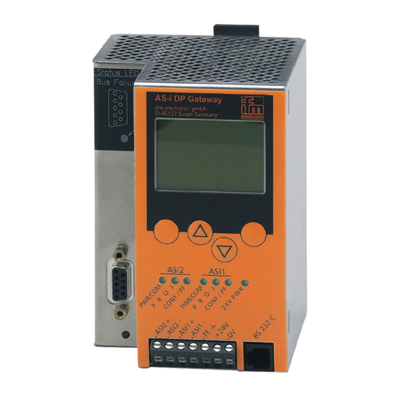
  • Seite 3: Bedien- Und Anzeigeelemente

    Versorgen Sie das AS-i DP Gateway mit einer Spannung von 24 V DC (20...30 V PELV), z. B. aus dem 24 V Netzteil DN2011 der ifm electro- nic. Der Anschluss erfolgt an den Klemmen +24 V und 0 V. Bedien- und Anzeigeelemente Sie werden von drei Diagnose-LEDs auf dem AS-i DP Gateway über den Zustand der Master und der angeschlossenen System informiert.
  • Seite 4 LED-Anzeigen und Anschlussbelegung Display Tasten ASI2 ASI1 RS232C Profibus-DP Busfehler Profibus-DP Schnittstelle...
  • Seite 5: Kontrasteinstellung

    Kontrasteinstellung Sie können den Kontrast direkt durch gleichzeitiges Drücken der rech- ten Taste mit der Δ-Taste (Darstellung ist zu hell) bzw. der ∇-Taste (...zu dunkel) verstellen. Kontrast verringern Kontrast erhöhen Betrieb Zum Betrieb eines AS-i Systems ist ein spezielles AS-i Netzteil erforder- lich (z.
  • Seite 6: Menü-Übersicht

    Menü-Übersicht Sie erreichen das Hauptmenü, Sie navigieren innerhalb eines indem Sie im Startdisplay die Menüpunktes, indem Sie die Tasten Δ oder ∇ drücken. linke Taste „MENU“ drücken. Drücken Sie die Tasten gleichzei- tig, um zwischen deutschem und englischem Menü zu wechseln. MENU-Taste Navigations-Tasten Menü-Navigation...
  • Seite 7 O System Setup (Einstellung des Gateway Gerätes) ∇ Eingabe des Passwortes zur Freigabe von Ände- rungen in der Systemkonfiguration ∇ Update der Firmware des Gateways (spezielle Programmiersoftware erforderlich) O System Info (Geräte Informationen) ∇ Hardware und Firmware Versionsnummern dieses Gateways ∇...
  • Seite 8 O Fieldbus Setup(Einstellung der Feldbusschnittstelle) ∇ Eingabe der Slave-Adresse des Gateways im überlagerten Profibus DP ∇ Weitere Eingaben über den überlagerten Profi- bus DP...
  • Seite 9: Function And Features

    Function and features • The AS-i DP gateway integrates 2 AS-i masters (AS-i version 3.0) and a Profibus DP interface • It controls the exchange of data to the sensor/actuator level • communicates with the higher control level (in the gateway mode) Interface RS232C The serial interface cannot be used.
  • Seite 10: Operating And Indicating Elements

    Supply the AS-i DP gateway with a 24 V DC voltage (20...30 V PELV), e.g. from the 24 V power supply DN2011 of ifm electronic. The connection is made to the terminals +24 V and 0 V. Operating and indicating elements Information concerning the state of the masters and the connected system is given via three diagnostic LEDs on the AS-i DP gateway.
  • Seite 11 LED indicators and pin connection display pushbuttons ASI1 ASI2 RS232C Profibus DP bus error Profibus DP interface...
  • Seite 12: Contrast Setting

    Contrast setting The contrast can be directly changed by simultaneously pressing the right button and the Δ-button (too bright) or the ∇−button (too dark). decrease contrast increase contrast Operation To operate an AS-i system a special AS-i power supply is required (e.g. AC1216).
  • Seite 13: Menu Overview

    Menu overview Open the main menu by pressing To navigate within a menu point press the button Δ or ∇. the left button "MENU" in the start display. Press the buttons simultaneously to switch between the German and English menu. Menu button Navigation buttons Menu navigation...
  • Seite 14 O System setup (Setting of the gateway device) ∇ Input of the password to enable changes in the system configuration ∇ Update of the gateway firmware (special pro- gramming software required) O System info (Device information) ∇ Hardware and firmware version numbers of this gateway ∇...
  • Seite 15 O Fieldbus setup (Setting of the fieldbus interface) ∇ Input of the slave address of the gateway in the higher-level Profibus DP ∇ Further inputs via the higher-level Profibus DP...
  • Seite 16: Fonctionnement Et Caractéristiques

    Fonctionnement et caractéristiques • La passerelle AS-i DP intègre deux maîtres AS-i (version AS-i 3.0) et une interface Profibus-DP. • Il contrôle l'échange de données avec le niveau capteurs/ action- neurs, • peut communiquer avec le niveau système de commande supérieur (mode passerelle).
  • Seite 17: Eléments De Service Et D'indication

    Alimenter la passerelle AS-i DP en 24 V DC (20...30 V TBTP), par ex. via l'alimentation 24 V DN2011 d'ifm electronic. Le raccordement se fait aux bornes +24 V et 0 V. Eléments de service et d'indication L'état des maîtres et du système raccordé est indiqué par trois LED de diagnostic sur la passerelle.
  • Seite 18 Voyants LED et raccordement des bornes affichage boutons ASI2 ASI1 Erreur sur réseau RS232C Profibus DP Interface Profibus-DP...
  • Seite 19 Réglage du contraste Le contraste peut être modifié directement en appuyant simultané- ment sur le bouton droit et le bouton Δ (trop clair) ou le bouton ∇ (trop foncé). réduire le contraste augmenter le contraste Fonctionnement Pour le fonctionnement d'un système AS-i une alimentation AS-i spé- cifique est nécessaire (par ex.
  • Seite 20: Aperçu Du Menu

    Aperçu du menu L'appui sur le bouton Δ ou ∇ per- Le menu principal est ouvert en appuyant sur le bouton gauche met une navigation dans un "MENU" dans l'écran de départ. point de menu. Appuyez sur les boutons-poussoirs simultané- ment pour changer entre le menu allemand et anglais.
  • Seite 21 O System Setup (Réglage de la passarelle) ∇ Saisie du mot de passe permettant de modifier la configuration du système ∇ Mise à jour du firmware de la passarelle (logiciel de programmation spécifique nécessaire) O System Info (Informations sur l'appareil) ∇...
  • Seite 22 O Fieldbus Setup (Réglage de l'interface bus de terrain) ∇ Saisie de l'adresse esclave de la passerelle dans le Profibus DP supérieur ∇ D'autres saisies via le Profibus DP supérieur...
  • Seite 23 Maßzeichnung Scale drawing Schéma d’encombrement...
  • Seite 24 Limited voltage / Current Das Gerät muss von einer galvanisch getrennten Quelle versorgt wer- den, die sekundär über eine UL- zugelassene Sicherung mit einem max. Nennstrom von a) 5 A bei Spannungen von 0...20 Vrms (0...28.3 Vp) oder b) 100/Vp bei Spannungen von 20...30 Vrms (28.3...42.4 Vp) verfügt.

Inhaltsverzeichnis