Herunterladen Inhalt Inhalt Diese Seite drucken
Aeris Swopper Montageanleitung
Vorschau ausblenden Andere Handbücher für Swopper:
Inhaltsverzeichnis

Werbung

Verfügbare Sprachen

Verfügbare Sprachen

Online UPS
EN
PowerWalker VFI 1000C LCD
PowerWalker VFI 2000C LCD
PowerWalker VFI 3000C LCD
Manual (EN, DE, ES)
Uninterruptible Power Supply System

Werbung

Inhaltsverzeichnis
loading

Inhaltszusammenfassung für Aeris Swopper

  • Seite 1 Online UPS PowerWalker VFI 1000C LCD PowerWalker VFI 2000C LCD PowerWalker VFI 3000C LCD Manual (EN, DE, ES) Uninterruptible Power Supply System...
  • Seite 3: Inhaltsverzeichnis

    Table of Contents 1. Important Safety Warning ....................1 1-1. Transportation ..................... 1 1-2. Preparation ......................1 1-3. Installation ......................1 1-4. Operation ......................1 1-5. Maintenance, service and faults ................2 2. Installation and setup ..................... 3 2-1. Rear panel view ....................3 2-2.
  • Seite 4: Important Safety Warning

    1. Important Safety Warning Please comply with all warnings and operating instructions in this manual strictly. Save this manual properly and read carefully the following instructions before installing the unit. Do not operate this unit before reading through all safety information and operating instructions carefully 1-1.
  • Seite 5: Maintenance, Service And Faults

    1-5. Maintenance, service and faults The UPS system operates with hazardous voltages. Repairs may be carried out only by  qualified maintenance personnel. Caution - risk of electric shock. Even after the unit is disconnected from the mains  (building wiring outlet), components inside the UPS system are still connected to the battery and electrically live and dangerous.
  • Seite 6: Installation And Setup

    2. Installation and setup NOTE: Before installation, please inspect the unit. Be sure that nothing inside the package is damaged. Please keep the original package in a safe place for future use. 2-1. Rear panel view 1000 2000 3000 1. AC input 2.
  • Seite 7: Intelligent Slot

    Step 2: UPS output connection For socket-type outputs, simply connect devices to the outlets.  For terminal-type input or outputs, please follow below steps for the wiring configuration:  a) Remove the small cover of the terminal block b) Suggest using AWG14 or 2.1mm power cords for 3KVA (200/208/220/230/240VAC models).
  • Seite 8: Operations

    3. Operations 3-1. Button operation Button Function  Turn on the UPS: Press and hold ON/Mute button for at least 2 seconds to turn on the UPS.  Mute the alarm: When the UPS is on battery mode, press and hold this button for at least 5 seconds to disable or enable the alarm system.
  • Seite 9 Display Function Remaining backup time information Indicates the remaining backup time in pie chart. Indicates the remaining backup time in numbers. H: hours, M: minute, S: second Fault information Indicates that the warning and fault occurs. Indicates the warning and fault codes, and the codes are listed in details in 3-5 section.
  • Seite 10: Audible Alarm

    3-3. Audible Alarm Battery Mode Sounding every 4 seconds Low Battery Sounding every second Overload Sounding twice every second Fault Continuously sounding Bypass Mode Sounding every 10 seconds 3-4. LCD display wordings index Abbreviation Display content Meaning Enable Disable Escape High loss Low loss Battery...
  • Seite 11 230: presents output voltage is 230Vac (Default) 240: presents output voltage is 240Vac For 100/110/150/120/127 VAC models, you may choose the following output voltage: 100: presents output voltage is 100Vac 110: presents output voltage is 110Vac 115: presents output voltage is 115Vac 120: presents output voltage is 120Vac (Default) 127: presents output voltage is 127Vac 02: Frequency Converter enable/disable...
  • Seite 12 (Default: -12V) For 100/110/115/120/127 VAC models, the setting voltage in parameter 3 is from -3V to -12V of the nominal voltage. (Default: -6V) 06: Bypass enable/disable when UPS is off  Interface Setting Parameter 3: Enable or disable Bypass function. You may choose the following two options: ENA: Bypass enable DIS: Bypass disable (Default)
  • Seite 13: Operating Mode Description

    3-6. Operating Mode Description Operating mode Description LCD display Online mode When the input voltage is within acceptable range, UPS will provide pure and stable AC power to output. The UPS will also charge the battery at online mode. ECO mode Energy saving mode: When the input voltage is within voltage regulation range, UPS will bypass...
  • Seite 14: Faults Reference Code

    3-7. Faults Reference Code Fault event Fault code Icon Fault event Fault code Icon Bus start fail Inverter voltage Low Bus over Inverter output short Bus under Battery voltage too high Bus unbalance Battery voltage too low Inverter soft start fail Over temperature Inverter voltage high Overload...
  • Seite 15: Troubleshooting

    4. Troubleshooting If the UPS system does not operate correctly, please solve the problem by using the table below. Symptom Possible cause Remedy No indication and alarm even The AC input power is not Check if input power cord though the mains is normal. connected well.
  • Seite 16 Symptom Possible cause Remedy Battery backup time is shorter Batteries are not fully Charge the batteries for at than nominal value charged least 5 hours and then check capacity. If the problem still persists, consult your dealer. Batteries defect Contact your dealer to replace the battery.
  • Seite 17: Storage And Maintenance

    5. Storage and Maintenance Operation The UPS system contains no user-serviceable parts. If the battery service life (3~5 years at 25°C ambient temperature) has been exceeded, the batteries must be replaced. In this case, please contact your dealer. Be sure to deliver the spent battery to a recycling facility or ship it to your dealer in the replacement battery packing material.
  • Seite 18: Specifications

    6. Specifications MODEL 1000 2000 3000 CAPACITY* 1000 VA / 800 W 2000 VA / 1600 W 3000 VA / 2400 W INPUT 85VAC/75VAC/65VAC/55VAC±5% or 160VAC/140VAC/120VAC/110VAC±5% Low Line Transfer (Ambient Temp.<35 ( based on load percentage 100% - 80 % / 80 % - 70 % / 70 - 60 % / 60 % - 0) Voltage 95VAC/85VAC/75VAC/65VAC or 175VAC/155VAC/135VAC/125VAC ±...
  • Seite 19: Unterbrechungsfreie Stromversorgung (Usv)

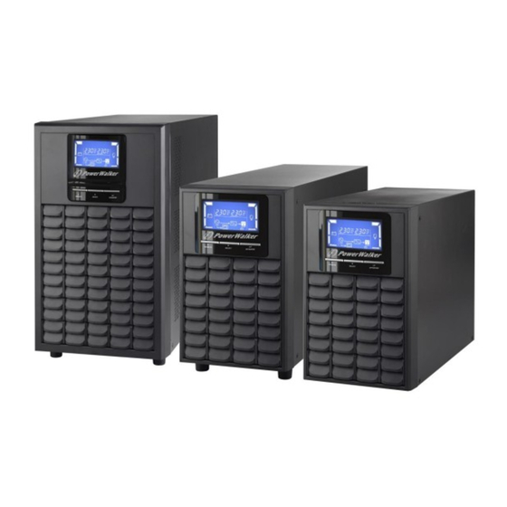
    Online-USV PowerWalker VFI 1000C LCD PowerWalker VFI 2000C LCD PowerWalker VFI 3000C LCD Bedienungsanleitung (DE) Unterbrechungsfreie Stromversorgung (USV)
  • Seite 21 Inhaltsverzeichnis 1. Wichtige Sicherheitshinweise ................... 1 1-1. Transport ......................1 1-2. Vorbereitung ....................... 1 1-3. Installation ......................1 1-4. Betrieb ........................ 1 1-5. Instandhaltung, Service und Fehlerbehebung ............2 2. Installation und Aufbau ....................3 2-1. Rückwand ......................3 2-2. Aufbau der USV ....................3 3.
  • Seite 22: Wichtige Sicherheitshinweise

    1. Wichtige Sicherheitshinweise Bitte beachten Sie strikt alle Warnhinweise und Bedienungsanleitungen in diesem Handbuch. Verwahren Sie diese Anleitung gut auf und lesen sorgfältig die folgenden Anweisungen, bevor Gerät installieren. Nehmen Gerät nicht Lesen aller Sicherheitsinformation und Betriebsanleitungen in Betrieb. 1-1. Transport Bitte transportieren Sie die USV nur in der Originalverpackung, um es vor Stößen zu ...
  • Seite 23: Instandhaltung, Service Und Fehlerbehebung

    1-5. Instandhaltung, Service und Fehlerbehebung Die USV wird mit gefährlichen Spannungen betrieben. Reparaturen dürfen nur von  qualifiziertem Wartungspersonal durchgeführt werden. Vorsicht - Stromschlagrisiko. Selbst wenn das Gerät ausgesteckt ist, sind Teile der  USV immer noch mit dem Akku verbunden und stehen unter Strom. Vor jeder Art von Service und/oder Instandhaltungsmaßnahmen klemmen Sie die ...
  • Seite 24: Installation Und Aufbau

    2. Installation und Aufbau HINWEIS: Bitte überprüfen Sie das Gerät vor der Installation. Vergewissern Sie sich, dass kein Teil beschädigt ist. Bitte bewahren Sie die Originalverpackung für weiteren Gebrauch auf. 2-1. Rückwand 1000 2000 3000 8. Wechselstrom-Eingang 9. Eingangssicherung 10. USB-Port 11.
  • Seite 25: Schritt 2: Usv-Ausgangsstecker

    Schritt 2: USV-Ausgangsstecker Wenn Buchsen als Ausgänge vorhanden sind, schließen Sie die Geräte einfach daran an.  Wenn Eingänge und Ausgänge in Form von Klemmen vorhanden sind, gehen Sie bei der  Verdrahtung wie folgt vor: a) Entfernen Sie die Abdeckung über der Kabelklemmung. b) Empfohlen sind AWG14 oder 2,1mm Stromkabel für 3KVA (Modelle 200/208/220/230/240VAC).
  • Seite 26: Betrieb

    3. Betrieb 3-1. Tastenbedienung Symbol Funktion  USV einschalten: Halten Sie die ON/Mute-Taste für mindesten 2 Sekunden gedrückt, um die USV einzuschalten.  Alarm stumm schalten: Sobald die USV im Akkubetrieb ist, halten Sie diese Taste für mindesten 5 Sekunden gedrückt, um den Alarm ein- oder auszuschalten.
  • Seite 27 Display Funktion Laufzeit Zeigt die verbleibende Überbrückungszeit als Tortendiagramm. Zeigt die verbleibende Überbrückungszeit als Wert. H: Stunden, M: Minute, S: Sekunde Fehlermeldung Zeigt Warnungen und Fehler an. Zeigt Warnung- und Fehlerkodierung an. Die Codes sind im Kapitel 3-5 detailliert aufgelistet. Stummschaltung Zeigt an, dass der USV-Alarm deaktiviert ist.
  • Seite 28: Akustischer Alarm

    3-3. Akustischer Alarm Akkumodus Ertönt alle 4 Sekunden Niedriger Ertönt jede Sekunde Akkustand Überlast Ertönt zweimal in jeder Sekunde Fehler Kontinuierlicher Alarmton Bypass-Modus Ertönt alle 10 Sekunden 3-4. LCD-Display Index der Formulierungen Abkürzung Anzeige Bedeutung Aktivieren Deaktivieren Escape Hohe Verlustrate Niedrige Verlustrate Akku Wandler...
  • Seite 29: Frequenzumwandler Aktiviert/Deaktiviert Schnittstelle

    220: Ausgangsspannung 220VAC 230: Ausgangsspannung 230VAC (Standard) 240: Ausgangsspannung 240VAC Für Modelle mit 100/110/150/120/127 VAC können Sie folgende Ausgangsspannung wählen: 100: Ausgangsspannung 100VAC 110: Ausgangsspannung 110VAC 115: Ausgangsspannung 115VAC 120: Ausgangsspannung 120VAC (Standard) 127: Ausgangsspannung 127VAC 02: Frequenzumwandler aktiviert/deaktiviert  Schnittstelle Einstellung Parameter 2 &...
  • Seite 30 (Standard: +6V) LLS: Niedrige Verlustspannung im Stromsparmodus mit Parameter 2. Für Modelle 200/208/220/230/240 VAC, kann der Einstellungsbereich des Parameters 3 von -7V bis-24V der nominalen Spannung eingestellt werden. (Standard: -12V) Für Modelle 100/110/115/120/127 VAC kann der Einstellungsbereich des Parameters 3 von -3V bis -12V der nominalen Spannung eingestellt werden.
  • Seite 31: Beschreibung Der Betriebsmodi

    3-6. Beschreibung der Betriebsmodi Betriebsmodus Beschreibung LCD-Anzeige Online-Modus Die USV erzeugt eine stabile, reine Wechselstromspannung, solange sich die Eingangsspannung im akzeptablen Bereich befindet. Der Akku der USV wird im Online-Modus geladen. Stromsparmodu Stromsparmodus: s (ECO-Modus) Wenn die Eingangsspannung im akzeptablen Bereich liegt, leitet die USV die Spannung direkt zum Ausgang, um Energie zu sparen.
  • Seite 32: Fehlerreferenzcode

    3-7. Fehlerreferenzcode Aufgetretener Fehlercode Symbol Aufgetretener Fehler Fehlercode Symbol Fehler Inverter Bus-Startfehler Niederspannung Inverter Bus über Ausgangskurzschluss Bus unter Akkuspannung zu hoch Akkuspannung zu Bus unausgeglichen niedrig Inverter Übertemperatur Softstart-Fehler Inverter Überlast Überspannung 3-8. Warnanzeige Warnung Symbol (blinkend) Alarm Niedriger Akkustand Ertönt jede Sekunde Überlast Ertönt zweimal in jeder Sekunde...
  • Seite 33: Problembehebung

    4. Problembehebung Wenn das USV-System nicht korrekt funktioniert, bitte das Problem anhand der nachstehenden Tabelle lösen. Symptom Mögliche Ursache Abhilfe Keine Anzeige oder Alarm trotz Das Stromkabel ist nicht Überprüfen, ob das normaler Stromversorgung. korrekt verbunden. Stromkabel fest eingesteckt ist. Das Stromkabel ist mit dem Stromkabel korrekt in den USV-Ausgang verbunden.
  • Seite 34 Symptom Mögliche Ursache Abhilfe Fehlercode 01, 02, 03, 04, 11, 12, Ein interner USV-Fehler ist Kontaktieren Sie Ihren 13 und 41 wird auf dem aufgetreten. Es gibt zwei Händler. LCD-Display angezeigt und der Möglichkeiten: Alarm ertönt kontinuierlich. 1. Die Stromversorgung erfolgt noch, jedoch direkt über den Bypass vom Wechselstromnetz.
  • Seite 35: Lagerung Und Instandhaltung

    5. Lagerung und Instandhaltung Betrieb Das USV-System enthält keine Teile, die der Benutzer warten kann. Falls die Akkulebensdauer (3~5 Jahre bei 25°C Umgebungstemperatur) überschritten wurde, müssen die Akkus ausgetauscht werde. Kontaktieren Sie in diesem Fall Ihren Händler. Bringen Sie gebrauchte Akkus zum Recycling oder senden Sie sie zu Ihrem Händler.
  • Seite 36: Spezifikationen

    6. Spezifikationen MODELL 1000 2000 3000 KAPAZITÄT* 1000 VA / 800 W 2000 VA / 1600 W 3000 VA / 2400 W EINGANG 85 VAC/75 VAC/65 VAC/55 VAC ±5% oder 160 VAC/140 VAC/120 VAC/110 VAC ±5% Niedrige Überleitung (Umgebungstemp.<35 (abhängig von der prozentualen Last 100% - 80 % / 80 % - 70 % / 70 - 60 % / 60 % - 0) 95VAC/85VAC/75VAC/65VAC oder 175VAC/155VAC/135VAC/125VAC ±...
  • Seite 38: Sistema De Alimentación Ininterrumpida

    SAI Online PowerWalker VFI 1000C LCD PowerWalker VFI 2000C LCD PowerWalker VFI 3000C LCD Manual (EN, ES) Sistema de Alimentación Ininterrumpida...
  • Seite 39 INDICE 1. Aviso Importante sobre seguridad ..................1 1-1. Transporte ......................1 1-2. Preparación ......................1 1-3. Instalación ......................1 1-4. Funcionamiento ...................... 1 1-5. Mantenimiento y reparación ................... 2 2. Instalación y configuración ..................... 3 2-1. Vista del panel posterior ..................3 2-2.
  • Seite 40: Aviso Importante Sobre Seguridad

    1. Aviso Importante sobre seguridad Siga estrictamente todas las advertencias e instrucciones de este manual. Guarde este manual y lea atentamente las siguientes instrucciones antes de instalar la unidad. No utilice este aparato sin antes leer con atención toda la información sobre seguridad e instrucciones. 1-1.
  • Seite 41: Mantenimiento Y Reparación

    1-5. Mantenimiento y reparación  El SAI funciona con voltajes peligrosos. Cualquier reparación debe ser realizada exclusivamente por personal cualificado.  Precaución - Riesgo de descarga eléctrica. Incluso después de desconectarse de la red, el cableado interno continúa conectado a la batería y la tensión es peligrosa. ...
  • Seite 42: Instalación Y Configuración

    2. Instalación y configuración NOTA: Antes de la instalación, por favor, compruebe la unidad. Asegúrese de que nada en el interior del embalaje esté dañado. Por favor, mantenga el embalaje original en un lugar seguro para un futuro uso. 2-1. Vista del panel posterior 1000 2000 3000...
  • Seite 43 Paso 2: Conexión de salida del SAI Para las salidas de tipo enchufe, simplemente conecte los dispositivos a las tomas de  corriente. Para las salidas tipo termina, por favor, siga los siguientes pasos para la configuración de los  cables: a) Quitar la pequeña tapa del bloque de terminales.
  • Seite 44: Operaciones

    3. Operaciones 3-1. Botones de funcionamiento Botón Función  Enciende el SAI. Mantenga pulsada la tecla ON/Mute durante 2 segundos para encender el SAI.  Silenciar la alarma: Cuando el SAI entra en modo de batería, mantenga pulsada la tecla durante al menos 5 segundos para activar o desactivar el sistema de alarma.
  • Seite 45 Display Función Información del tiempo de autonomía restante Indica el tiempo de autonomía con reloj analógico Indica el tiempo de autonomía con reloj digital. H: horas, M: minutos, S: segundos Información del error Indica una alarma o error. Indica el código del aviso y del error, detallados en la sección 3-5. Funcionamiento sin alarma Indica que la alarma sonora está...
  • Seite 46: Alarma Acústica

    3-3. Alarma acústica Modo batería Sonido cada 4 segundos Batería baja Sonido cada segundo Sobrecarga Dos sonidos cada segundo Avería Sonido continuado Modo bypass Sonido cada 10 segundos 3-4. Indicaciones en la pantalla Abreviaciones Indicación del Display Significado Habilitado Deshabilitado Escape Fuerte pérdida Pérdida baja...
  • Seite 47 01: Ajuste de la tensión de salida  Interfaz Configuración Parameter 3: Output voltage Voltaje de salida (Parámetro 3) Para los modelos 208/220/230/240 VAC, se puede elegir el voltaje de salida siguiente: 200: la tensión de salida es de 200Vac 208: la tensión de salida es de 208Vac 220: la tensión de salida es de 220Vac 230: la tensión de salida es de 230Vac (Por defecto)
  • Seite 48 Interfaz Configuración Parámetros 2 y 3: Ajuste los límites aceptables de alta y baja tensión en modo ECO pulsando Down key o Up key. HLS: Alta pérdida de tensión en modo ECO en el parámetro 2 Para modelos 200/208/220/230/240 Vac, el rango de ajuste en el parámetro 3 es de +7V a +24V de la tensión nominal.
  • Seite 49: Configuración

    Interfaz Configuración Parámetro 3: Fija los límites del tiempo de autonomía para las tomas generales. 0-999: ajusta el tiempo de autonomía en minutos desde 0-999 para las tomas generales en modo batería. 0: Cuando la configuración es "0", el tiempo de backup será sólo de 10 segundos.
  • Seite 50: Descripción Del Modo Operative

    3-6. Descripción del modo operative Modo operativo Descripción Display LCD Modo Online Cuando el voltaje de entrada está dentro del rango aceptable, el SAI proporcionará una corriente alterna (CA) de salida limpia y estable. Al mismo tiempo, el SAI carga la batería en modo online.
  • Seite 51: Códigos De Error

    3-7. Códigos de error Causa del fallo Nº error Icono Causa del fallo Nº error Icono No se enciende Volt. inverter bajo Volt. Entrada alto Corto inverter salida Volt. Entrada bajo Volt. batería alto Entrada no balanceada Volt. Batería bajo Error arranque Inverter Sobrecalentamiento Volt.
  • Seite 52: Solución De Problemas

    4. Solución de problemas Si el SAI no funciona correctamente, por favor, resuelva el problema utilizando el cuadro siguiente. Síntoma Posibles causas Remedio Sin indicación ni alarma, incluso si La entrada de red CA no Compruebe si el cable de la alimentación es normal.
  • Seite 53 Síntoma Posibles causas Remedio El código de error indica: 01, 02, Ha ocurrido un fallo interno Póngase en contacto con 03, 04, 11, 12, 13 y 41 en el de SAI. Hay dos posibles su servicio asistencia. display LCD y la alarma suena causas: continuamente.
  • Seite 54: Almacenamiento Y Mantenimiento

    5. Almacenamiento y mantenimiento Intervención El SAI contine partes no reutilizables. La batería tiene una vida de 3 ~ 5 años a 25 ° C de temperatura ambiente. Cuando tengan que ser sustituidos, por favor, póngase en contacto con su servicio asistencia. Asegúrese de entregar la batería gastada en un centro de reciclaje.
  • Seite 55: Especificaciones

    6. Especificaciones MODELO 1000 2000 3000 CAPACIDAD* 1000 VA / 800 W 2000 VA / 1600 W 3000 VA / 2400 W ENTRADA 85VAC/75VAC/65VAC/55VAC±5% or 160VAC/140VAC/120VAC/110VAC±5% Transferencia por baja (Temperatura Ambiente<35 tensión en línea ( base en % carga: 100% - 80 % / 80 % - 70 % / 70 - 60 % / 60 % - 0) Rango 95VAC/85VAC/75VAC/65VAC or 175VAC/155VAC/135VAC/125VAC ±...

Inhaltsverzeichnis