Herunterladen Inhalt Inhalt Diese Seite drucken
Evolution FURY3-XL Original Instructions

Evolution FURY3-XL Original Instructions

Mehrzweck-gehrungssäge
Vorschau ausblenden Andere Handbücher für FURY3-XL:
Inhaltsverzeichnis

Werbung

Verfügbare Sprachen
  • DE

Verfügbare Sprachen

EN
Original Instructions
ES Instructions d'origine
FR Instructions Originales
DE Original Anweisungen
IT
Istruzioni Originali
Original written in UK English
STEALTH
NL
Origineel Instructies
PL Oryginalna instrukcja
PT Instruções Originais
RU Оригинальные Инструкции
TR Orijinal Talimatlar
Date Published: 27 / 04 / 2017
255

Werbung

Inhaltsverzeichnis
loading

Inhaltszusammenfassung für Evolution FURY3-XL

  • Seite 1 STEALTH Original Instructions Origineel Instructies ES Instructions d’origine PL Oryginalna instrukcja FR Instructions Originales PT Instruções Originais DE Original Anweisungen RU Оригинальные Инструкции TR Orijinal Talimatlar Istruzioni Originali Original written in UK English Date Published: 27 / 04 / 2017...
  • Seite 3 ENGLISH Original Instructions...
  • Seite 4: Inhaltsverzeichnis

    www.evolutionpowertools.com TABLE OF CONTENTS MACHINE SpECIFICATION Introduction Guarantee Vibration Intended use of this Power Tool Prohibited use of this Power Tool SAFETY pRECAUTIONS Electrical Safety General Power Tool Safety Instructions Health Advice Specific Safety Instructions Personal Protective Equipment (PPE) Safe Operation Aditional Safety Advice GETTING STARTED Unpacking...
  • Seite 5 www.evolutionpowertools.com...
  • Seite 6: Machine Specification

    www.evolutionpowertools.com 210mm (8-1/4”) TCT MULTIpURpOSE SLIDING MITRE SAwS Specification Metric Imperial Designed to cut Mild Steel Plate – Max Thickness 1/8” Mild Steel Box Section – Max Wall Thickness 1/8” Wood – Max Section 60mm x 220mm 2-3/8” x 8-3/4” Motor (230-240V~ 50Hz) 1500W No Load Speed...
  • Seite 7 www.evolutionpowertools.com STEALTH 255mm (10”) TCT MULTIpURpOSE SLIDING MITRE SAwS Specification Metric Imperial Designed to cut Mild Steel Plate – Max Thickness 1/8” Mild Steel Box Section – Max Wall Thickness 1/8” Wood – Max Section 75mm x 300mm 3” x 11-3/4” Motor (230-240V~ 50Hz) 2000W (Soft Start) 9A (Soft Start)
  • Seite 8: Introduction

    (following list (1.4) not exhaustive) blades, cutters, drills, chisels Congratulations on your purchase or paddles etc. In no event shall Evolution of an Evolution power Tools Machine. Power Tools be liable for loss or damage please complete your product registration resulting directly or indirectly from the use ‘online’...
  • Seite 9: Vibration

    If any of the symptoms become evident, Do not operate this machine if seek immediate medical advice. warning and/or instruction labels are missing or damaged. Contact Evolution Power Tools for a. The actual vibration level during use will replacement labels. depend on the workpiece stability/rigidity...
  • Seite 10: Intended Use Of This Power Tool

    This machine is fitted with the correct Sliding Mitre Saw and has been designed to moulded plug and mains lead for the be used with special Evolution Multipurpose designated market. If the supply cord is blades. Only use blades designed for use in...
  • Seite 11 www.evolutionpowertools.com SAVE ALL wARNINGS AND location is unavoidable, use a residual INSTRUCTIONS FOR FUTURE current device (RCD) protected supply. REFERENCE. Use of an RCD reduces the risk of electric shock. The term “power tool” in the warnings refers to (2.4) your mains-operated (corded) power tool or 3) General power Tool Safety warnings battery-operated (cordless) power tool.
  • Seite 12: Health Advice

    www.evolutionpowertools.com (2.5) (2.6) 4) General power Tool Safety warnings 5) General power Tool Safety warnings [Service]a) Have your power tool serviced by [power tool use and care]. a qualified repair person using only identical a) Do not force the power tool. Use the correct power tool for your application.
  • Seite 13: Mitre Saw Specific Safety

    www.evolutionpowertools.com (3.5) (3.6) MITRE SAw SpECIFIC SAFETY pERSONAL pROTECTIVE EQUIpMENT (ppE) The following specific safety instructions for Mitre Saws are based on the requirements of EN 61029-2-9:2012+A11. Hearing protection should be worn in order to reduce the risk of induced hearing loss. BLADE SAFETY Eye protection should be worn in order to prevent the possibility of the loss of sight from...
  • Seite 14: Safe Operation

    www.evolutionpowertools.com SAFE OpERATION (3.7) Never attempt to retrieve off-cuts or any other part of the work piece until the cutting head is Always ensure that you have selected the correct in the raised position, the guard is fully closed saw blade for the material being cut. Do Not use and the saw blade has stopped rotating.
  • Seite 15: Getting Started - Unpacking

    These include the following items: machines safety features before attempting to operate the machine. Additional accessories and information on the use and type of accessory suitable for your machine can be obtained by contacting your local dealer or Evolution Power Tools.
  • Seite 16: Machine Overview

    www.evolutionpowertools.com OVERALL VIEw OF MITRE SAw 12. MITRE HANDLE 1. ON/OFF TRIGGER SWITCH 13. MITRE ANGLE SCALE 2. BLADE GUARD LOCKING TRIGGER 14. POSITIVE STOP LOCKING LEVER 3. CUTTING HANDLE 15. WORKPIECE SUPPORT (Optional Accessory) 4. DUST BAG (Optional Accessory) 16.
  • Seite 17: Assembly And Preparation

    www.evolutionpowertools.com (7.1) ASSEMBLY AND pREpARATION wARNING: Always disconnect the saw from the power source before making any adjustments. Note: It is recommended that all instructions are always read before operating. (7.2) permanently mounting the mitre saw To reduce the risk of injury from unexpected saw movement, Fig.
  • Seite 18 • Never exchange the laser module assembly for a different type or class of laser. • Repairs to the laser module must only be conducted by Evolution Power Tools or their authorized agent.
  • Seite 19 www.evolutionpowertools.com LASER ADJUSTMENT FOR EUROpEAN pLUG MODELS wARNING: At no time during this procedure should the motor be started. To check laser alignment: • Place a piece of cardboard, or similar, onto the rotary table of the machine. • With the carriage slide in the rearmost position, lower the Cutting (a)(b) Head so that a blade tooth makes a mark in the cardboard.
  • Seite 20 www.evolutionpowertools.com LASER ADJUSTMENT FOR NORTH AMERICAN pLUG MODELS wARNING: At no time during this procedure should the motor be started. The Laser Module is held in a ‘mounting block’ , The ‘mounting block, itself is located within the machine on two (2) sprung loaded socket headed screws.
  • Seite 21: Laser Safety

    www.evolutionpowertools.com Note: The above adjustments & alignments should be checked on a regular basis to ensure laser accuracy. Note: The following WARNING labels may be found on this machine: LASER RADIATION DO NOT STARE INTO THE BEAM CLASS 2 LASER pRODUCT LASER SAFETY Never look into the laser beam.
  • Seite 22: Depth Stop

    www.evolutionpowertools.com To use the laser guide for an unknown angle: • Mark the position of the cut to be made on the workpiece using a pencil etc. • Place the workpiece on the rotary table and against the fence. • Adjust the mitre saw to give the approximate angle of cut. Do not tighten the mitre lock handle at this stage.
  • Seite 23: Operating Instructions

    www.evolutionpowertools.com • When cutting is complete re-adjust the depth stop so that the Cutting Head can be locked in the down position by the head latching pin. Note: In many circumstances the depth stop can be left at the selected setting if desired. When the depth stop ‘stop plate’ is re- turned to the ‘normal’...
  • Seite 24: Body And Hand Positioning

    www.evolutionpowertools.com (8.3) (8.4) BODY AND HAND pOSITIONING ADjUSTMENT OF pRECISION ANGLES (Fig. 11) • Never place your hands within the ‘no hands Several checks/adjustments are possible on this zone’ (at least 150mm away from the blade). machine. The operator will require a 90 Keep hands away from the path of the blade.
  • Seite 25 www.evolutionpowertools.com BEVEL ANGLES (0 AND 45 Bevel Stop Adjustment • Ensure that the Cutting Head is in the locked down position with the latching pin fully engaged in its socket. • Ensure that the Cutting Head is upright, against its stop and on the scale.
  • Seite 26: Fence Alignment

    www.evolutionpowertools.com Bevel Stop Adjustment • Loosen the Bevel Lock Handle and tilt the Cutting Head completely to the left until it rests against the 45 stop. • Use a Set Square to see if the blade is at 45 to the table (avoiding the TCT tips).
  • Seite 27: Preparing To Make A Cut

    www.evolutionpowertools.com • Ensure that the Cutting Head is in the locked down position with the latching pin fully engaged in its socket • Place a Set Square on the table with one short edge against the Fence and the other short edge against the Blade (avoiding the TCT tips).
  • Seite 28: Chop Cutting

    www.evolutionpowertools.com UNLATCHING AND RAISING THE CUTTING HEAD Step 1 & 2 (Fig. 21) wARNING: To avoid serious injury, NEVER perform the unlocking or locking procedure unless the saw is OFF and the blade stopped. To Release the Cutting Head from the Locked Down position: • Gently press down on the Cutting Handle.
  • Seite 29 www.evolutionpowertools.com • Tighten the slide lock screw. (Fig. 24) • Place the workpiece on the table and against the fence and secure with clamp(s) as appropriate. • Grasp the saw handle. • Turn the motor on and allow the saw blade to reach full speed. • Remember to press the lock-off button first before the On/Off switch.
  • Seite 30: Mitre Cutting

    www.evolutionpowertools.com • Always push the Cutting Head to the full rear position during each cut. (Fig. 28) • When the cut has been completed, release the trigger switch and allow the blade to come to stop. • Allow the Cutting Head to rise to its upper position, with the lower blade guard completely covering the blade teeth, and the Cutting Head locked in the upper position, before releasing the Cutting Handle.
  • Seite 31 www.evolutionpowertools.com BEVEL CUTTING - TILTING THE CUTTING HEAD A bevel cut (Fig. 32) is made with the rotary table set at 0 mitre. Note: It may be necessary to adjust the upper section of the Fence to provide clearance for the moving Cutting Head. The Cutting Head can be tilted from the normal 0 (perpendicular position) to a maximum angle of 45...
  • Seite 32: Compound Cutting

    www.evolutionpowertools.com Ensure that the Crown Moulding is correctly positioned on the rotary table before making the cut. When cutting operations are completed, return the Cutting Head to the vertical position and return the Crown Moulding Pin to its outer (disengaged) positioned. (8.7) COMpOUND CUTTING (Fig.
  • Seite 33: Installing Or Removing A Blade

    Only use genuine Evolution blades or those blades specifically recommended by Evolution Power Tools and which are designed for this machine. Ensure that the maximum speed of the blade is higher than the speed of the motor.
  • Seite 34: Use Of Additional Accessories

    (8.12) USE OF OpTIONAL EVOLUTION ACCESSORIES Not supplied as original equipment. All accessories can be purchased from Evolution power Tools. See ‘Additional Accessories’ section.(8.13) DUST BAG A Dust Bag can be fitted to the extraction port at the rear of the machine.
  • Seite 35 www.evolutionpowertools.com Note: Approximately 75mm of the Workpiece Support Bar should slide into the base to provide positive location. • Tighten the retaining screw. • Repeat the above for the Left Hand side. To remove a Workpiece Support Bar, simply loosen the relevant retaining screw and slide the Workpiece Support Bar from the machine.
  • Seite 36: Final Safety Check List

    www.evolutionpowertools.com FINAL SAFETY CHECKS Condition Slides Inserted through the Bevel Neck and connected to the Cutting Head. Locating lugs successfully deployed Positive Stop Installed onto Locking Mechanism Locking Lever Mitre Locking Handle Installed onto Locking Screw Power Cable Routed correctly and fastened to back slide bracket. 50 –...
  • Seite 37: Maintenance

    Replacement EUROpEAN UNION inserts (sold in handed pairs) are available from your supplier or Evolution Power Tools. If you wish to discard electrical and electronic To replace the table inserts: equipment, please contact your dealer or • Remove the 3 or 4 cross-head screws that...
  • Seite 38: Ec Declaration Of Conformity

    EC DECLARATION OF CONFORMITY The manufacturer of the product covered by this Declaration is: Evolution Power Tools, Venture One, Longacre Close, Holbrook Industrial Estate, Sheffield, S20 3FR. The manufacturer hereby declares that the machine as detailed in this declaration fulfils all the relevant provisions of the Machinery Directive and other appropriate directives as detailed below.
  • Seite 39 EC DECLARATION OF CONFORMITY The manufacturer of the product covered by this Declaration is: Evolution Power Tools, Venture One, Longacre Close, Holbrook Industrial Estate, Sheffield, S20 3FR. The manufacturer hereby declares that the machine as detailed in this declaration fulfils all the relevant provisions of the Machinery Directive and other appropriate directives as detailed below.
  • Seite 41 FRANÇAIS Traduction de manuels d’instruction d’origine...
  • Seite 42 www.evolutionpowertools.com TABLE DES MATIÈRES SPéCIFICATIoNS DE LA mACHINE Présentation Garantir Vibration Utilisation prévue de cet outil électrique Interdiction d'utiliser cet outil électrique mESURES DE SéCURITé Sécurité électrique Généraux pour les outils Consignes de sécurité Conseils de santé Consignes de sécurité spécifiques Équipement de protection individuelle (EPI) Operation Safe Conseils de sécurité...
  • Seite 43 www.evolutionpowertools.com...
  • Seite 44: Spécifications De La Machine

    www.evolutionpowertools.com 210mm TCT MULTIpURpOSE SCIES à ONGLETS Spécifications Métrique Impérial Conçu pour couper Mild steel plate - epaisseur max 1/8” Boîte en acier doux section - epaisseur max mur 1/8” Bois - section max 60mm x 220mm 2-3/8” x 8-3/4” Moteur (230-240V~ 50Hz) 1500W Vitesse à...
  • Seite 45 www.evolutionpowertools.com STEALTH 255mm MULTIpURpOSE SCIES à ONGLETS Spécifications Métrique Impérial Conçu pour couper Mild steel plate - epaisseur max 1/8” Boîte en acier doux section - epaisseur max mur 1/8” Bois - section max 75mm x 300mm 3” x 11-3/4” Moteur (230-240V~ 50Hz) 2000W Vitesse à...
  • Seite 46: Présentation

    (1.3) (1.5) IMpORTANT Evolution Power Tools sera, dans la période de garantie, et à partir de la date d’achat originale, S’il vous plaît lire les instructions de réparer ou remplacer tout produit reconnu fonctionnement et de sécurité attentivement défectueux dans les matériaux ou de fabrication.
  • Seite 47: Vibration

    Les utilisateurs qui utilisent des scies à onglet sur endommagées. S’adresser à Evolution Power de longues durées ou régulièrement, doivent Tools pour remplacer ou échanger les étiquettes.
  • Seite 48: Utilisation Prévue De Cet Outil Électrique

    être et/ou des lames qui ont été spécialement qualifié pour ce faire : la machine contient des recommandées par Evolution Power Tools Ltd. tensions dangereuses. Si cette machine est équipée de la lame de (1.15)
  • Seite 49: Conseils De Santé

    www.evolutionpowertools.com AVERTISSEMENT: les tuyaux, radiateurs, cuisinières et Avertissement ! Lire réfrigérateurs. Il existe un risque élevé tous les avertissements et toutes les consignes de chocs électriques si le corps entre en de sécurité. Le non-respect des avertissements contact avec un objet relié à la terre. et des instructions ci-dessous peut avoir pour •...
  • Seite 50 www.evolutionpowertools.com • Ne pas utiliser l’outil électrique si personnel, comme par ex. un masque l’interrupteur marche/arrêt est hors antipoussière, des chaussures de sécurité d’usage. Un outil électrique qui ne peut antidérapantes et une protection auditive qui sera utilisé conformément aux conditions de être mis en ou hors service est dangereux travail peut réduire le risque de blessure.
  • Seite 51: Consignes De Sécurité Spécifiques

    www.evolutionpowertools.com avec l’utilisation de pièces de rechange (3.5) SÉCURITÉ DE LA LAME DE SCIE d’origine. Cela permet de garantir la sécurité dans la durée de l’outil électrique. AVERTISSEMENT: • Faire entretenir l’outil électrique par Les lames de scie un spécialiste qualifié et uniquement qui sont en rotation sont extrêmement avec l’utilisation de pièces de rechange dangereuses et peuvent causer des blessures...
  • Seite 52: Fonctionnement Sûr

    www.evolutionpowertools.com Il est également conseillé de porter une les coupes. Toujours contrôler et s’assurer que la protection respiratoire car certains types de bois vitesse de rotation indiquée sur la lame de scie correspond au moins à la vitesse de rotation et de produits comparables au bois, en particulier le MDF (panneau de fibres de densité...
  • Seite 53: Conseils De Sécurité Additionnelle

    www.evolutionpowertools.com AVERTISSEMENT: supports fournis ou sur un support de travail ne pas utiliser le dispositif supplémentaire approprié. de protection de lame de scie comme « poignée de levage ». Avant de transporter la machine, AVERTISSEMENT: Il est possible lors de débrancher la fiche électrique de la prise murale.
  • Seite 54: Pièces Fournies

    Référence Description pièce • Instructions de service DIAMOND210 • Pince à pièce à usiner Evolution • Clé hexagonale de 5 mm (pour le lame de diamant DIAMOND255 remplacement de la lame de scie) • Extension Latérale clé hexagonale Récipient collecteur EV3S174 ou • Lame de scie multi-usages...
  • Seite 55: Vue D'ensemble Des Pièces

    www.evolutionpowertools.com VUE D’ENSEMBLE DES pIÈCES 13. Échelle d’angle de coupe 1. Interrupteur marche/arrêt 14. Levier de fixation butée positive 2. Loquet de fixation protection de la lame 15. Support de pièce à usiner de scie (accessoire en option) 3. poignée de coupe 16.
  • Seite 56: Assemblage Et Préparation

    www.evolutionpowertools.com (7.1) ASSEMBLAGE ET pRÉpARATION AVERTISSEMENT: avant de procéder aux réglages, toujours débrancher la fiche électrique de la scie de la prise électrique murale. Remarque: il est recommandé de toujours lire toutes les instructions avant la mise en service de la scie. (7.2) Montage permanent de la scie à...
  • Seite 57 www.evolutionpowertools.com Si l’appareil est équipé en conséquence, le bras doit être sorti de l’embase, en particulier si la machine est utilisée autonome sur un établi. (Fig. 3) Ce bras assure une stabilité particulièrement bonne et empêche que la machine ne tombe en cas de désolidarisation brutale de la tête de coupe.
  • Seite 58 • Ne jamais remplacer le module laser par un laser d’un autre type ou d’une autre classe. • Les réparations du module laser sont strictement réservées à Evolution Power Tools ou un autre service après-vente agréé. AJUSTEMENT POUR LASER MODÈLES pRISE EUROpÉENNE AVERTISSEMENT: il est absolument interdit de démarrer le...
  • Seite 59 www.evolutionpowertools.com A. Si le rayon laser n’est pas parallèle avec les marquages, procéder de la manière suivante: • Desserrer la vis de serrage (Fig. 6 a) • Tourner le module laser (Fig. 6 b) avec précaution jusqu’à ce que la ligne soit parallèle aux marquages sur le carton. • Resserrer la vis de serrage.
  • Seite 60 www.evolutionpowertools.com pour vérifier l’alignement laser : • Placez le gabarit en carton du laser (fourni) sur la table rotative (Fig. 8c). • Baissez la tête de coupe et tracez le parcours de la lame sur le gabarit en carton en glissant le tête de coupe en avant et en arrière. • Positionnez le carton de telle sorte que le parcours de la lame marqué sur le gabarit corresponde exactement au parcours réel de la lame. • Fixez le gabarit en carton en place en utilisant du ruban à...
  • Seite 61: Sécurité Laser

    www.evolutionpowertools.com SÉCURITÉ LASER Le dispositif de guidage laser mis en œuvre dans ce produit utilise un laser de la classe 2 avec une puissance de sortie maximale de 1,5 mW et une longueur d’onde entre 365 et 670 nm. Les rayons laser ne causent normalement aucun dommage optique, mais regarder dans le rayon peut entraîner une cécité...
  • Seite 62 www.evolutionpowertools.com Utilisation du guidage laser pour un angle inconnu : • Identifier la coupe requise au moyen d’un crayon à papier ou équivalent sur la pièce à usiner. • Déposer la pièce à usiner sur la table rotative et contre la butée. • Disposer la scie sur l’angle de coupe approximatif.
  • Seite 63: Instructions De Commande

    www.evolutionpowertools.com pour utiliser la butée de profondeur : • Déployez la plaque d’arrêt de la butée de profondeur (a) en la poussant complètement vers la gauche. • Desserrez l’écrou à ailettes. (b) • Ajustez l’écrou à croisillon (c) pour limiter la course de la tête de la scie à la profondeur désirée. • Une fois réglée la profondeur désirée, resserrez l’écrou à ailettes (a) contre l’étrier de maintien afin de bloquer la butée de profondeur et de s’assurer qu’elle est fixe.
  • Seite 64 www.evolutionpowertools.com (8.2) • Éviter les mouvements et positions des mains AVERTISSEMENT: Toujours débrancher la fiche défavorables avec lesquelles les doigts ou la main pourraient parvenir dans la lame de scie électrique de la scie pour éviter tout risque de blessure avant de remplacer ou de régler les pièces du fait d’un dérapage soudain.
  • Seite 65 www.evolutionpowertools.com ANGLE D’INCLINAISON (0° ET 45°) 0° Réglage de la butée d’angle d’inclinaison • S’assurer que la tête de coupe se trouve dans la position de verrouillage inférieure et que la tige de fixation est totalement encliquetée. (cf. Fig. 19). • S’assurer que la tête de coupe est en position verticale contre sa butée et que l’indicateur d’angle d’inclinaison est sur 0°...
  • Seite 66 www.evolutionpowertools.com Réglage à 45° de la butée d’angle d’inclinaison • Desserrer la poignée de fixation pour l’angle d’inclinaison et basculer la tête de coupe complètement vers la gauche jusqu’à ce qu’elle repose contre la butée de 45°. • Contrôler avec une équerre si la lame de scie se trouve à un angle de 45°...
  • Seite 67 www.evolutionpowertools.com Orientation de la butée • La butée doit être orientée à 90° (angle droit). • Régler la table rotative sur l’angle de coupe ‹0°’ . • La butée est fixée avec deux vis Allen qui se trouvent sur les deux côtés de la butée dans les fentes longues.
  • Seite 68: Mise En Marche Et Arret

    www.evolutionpowertools.com DÉVERROUILLAGE OU SOULÈVEMENT DE LA TêTE Etapes 1 et 2 DE COUpE (Fig. 21) AVERTISSEMENT: Ne jamais exécuter le processus de déverrouillage ou de verrouillage avant que la scie n’ait été mise hors service et que la lame de scie ne soit à l’arrêt pour éviter des blessures graves.
  • Seite 69 www.evolutionpowertools.com Le chariot doit être verrouillé dans sa position la plus arrière. (Fig. 23) • Pousser la tête de coupe aussi loin que possible vers l’arrière. • Serrer la vis de verrouillage du chariot. (Fig. 24) • Déposer la pièce à usiner sur la table, l’appuyer contre la butée et la bloquer avec un ou plusieurs serrages suivant ce qui est requis.
  • Seite 70: Coupes D'onglet

    www.evolutionpowertools.com • Saisir la poignée de coupe et tirer la tête de coupe vers l’avant jusqu’à ce que le moyeu (centre de la lame) se trouve au-dessus du bord avant de la pièce à usiner. (Fig. 27) • Actionner l’interrupteur Marche/arrêt du moteur et laisser la lame de scie atteindre sa vitesse totale. • Appuyer sur le déclencheur du verrouillage de protection inférieur pour déverrouiller la tête de coupe. • Pousser la tête de coupe tout en bas et couper à travers le bord avant de la pièce à...
  • Seite 71 www.evolutionpowertools.com • Tourner la table rotative à l’angle souhaité. Pour aider au réglage, une échelle angulaire pour la coupe d’onglet est gravée dans l’embase de la machine. • Fixer la poignée de fixation pour l’angle de coupe une fois que l’angle est atteint. Remarque: Serrer la poignée de fixation pour l’angle de coupe également lorsqu’une butée positive a été...
  • Seite 72 www.evolutionpowertools.com • Attendre jusqu’à ce que la tête de coupe ait atteint sa position supérieure et que la protection de la lame de scie soit totalement fermée avant de retirer la(les) main(s). • Ramener la tête de coupe dans la position verticale. • Serrer l’élément de fixation pour l’angle d’inclinaison.
  • Seite 73 INSTALLATION ou RETRAIT d’une LAME ATTENTION : Ne réalisez cette opération que si l’outil est débranché du secteur. ATTENTION : N’utilisez que des lames Evolution d’origine ou des lames spécifiquement recommandées pour les outils Evolution Power Tools conçues pour cet outil. Assurez-vous que la vitesse maximum de la lame est supérieure à...
  • Seite 74: Accessoires En Option

    être utilisées qu’en accord avec les instructions du fabricant.» (8.12) ACCESSOIRES EN OpTION Ne sont pas fournis dans l’équipement d’origine. Tous les accessoires peuvent être acquis auprès d’Evolution Power Tools. Voir le chapitre « Accessoires supplémentaires ». Fig. 41 (8.13) SAC à...
  • Seite 75: L'utilisation D'accessoires Supplémentaires

    www.evolutionpowertools.com Remarque: our conserver une puissance maximale, vider le sac à poussières lorsqu’il est rempli aux 2/3. Éliminer le contenu du sac à poussières dans le respect de l’environnement. Lors de la vidage du sac à poussière, il peut s’avérer nécessaire de porter un masque anti-poussières.
  • Seite 76 www.evolutionpowertools.com Butée de tronçonnage (Fig. 43) L’utilisation de la butée de tronçonnage peut être une aide précieuse pour l’utilisateur lorsque les coupes de répétition sont réalisées. Lorsque de nombreux morceaux de matériau ont tous été coupés à la même longueur, la butée de tronçonnage permet une précision et une efficacité...
  • Seite 77: Liste De Vérification De Sécurité Final

    www.evolutionpowertools.com CONTRÔLES DE SÉCURITÉ FINALES Etat Rails de glissement Inséré dans le chariot et fixé sur la tête de coupe. Tiges de positionnement mises correctement en place. Levier de fixation butée Monté sur le mécanisme de fixation. positive Poignée de fixation Monté...
  • Seite 78: Entretien

    Les inserts de rechange (uniquement par paires) sont disponibles auprès Contrôler régulièrement si tous les systèmes du revendeur ou d’Evolution Power Tools. de sécurité et tous les dispositifs de protection fonctionnent correctement. Utiliser la machine Remplacement des inserts de table : uniquement si tous les dispositifs de protection • Ôter les 3 ou 4 vis cruciformes avec lesquelles...
  • Seite 79: Protection De L'environnement

    www.evolutionpowertools.com pOUR LES UTILISATEURS (6.4) pROTECTION DE D’ ENTREpRISE DANS L’ENVIRONNEMENT L’UNION EUROpÉENNE produits des déchets électriques ne Si vous souhaitez vous défaire d’équipements doivent pas être jetés avec les ordures électriques et électroniques , s’il vous plaît ménagères. S’il vous plaît recycler où les contactez votre revendeur ou fournisseur pour équipements existent.
  • Seite 80: Déclaration Ce De Conformité En

    DÉCLARATION DE CONFORMITÉ CE Le fabricant du produit couvert par cette déclaration est: Evolution Power Tools, Venture One, Longacre Close, Holbrook Industrial Estate, Sheffield, S20 3FR. Le fabricant déclare par le présent document que la machine dont les détails se trouvent dans cette déclaration est conforme à...
  • Seite 81 DÉCLARATION DE CONFORMITÉ CE Le fabricant du produit couvert par cette déclaration est: Evolution Power Tools, Venture One, Longacre Close, Holbrook Industrial Estate, Sheffield, S20 3FR. Le fabricant déclare par le présent document que la machine dont les détails se trouvent dans cette déclaration est conforme à...
  • Seite 83 DEUTSCH Übersetzung Original Bedienungsanleitungen...
  • Seite 84 www.evolutionpowertools.com INHALTSVERZEICHNIS TECHNISCHE DATEN Allgemeine Sicherheitshinweise für Elektrowerkzeuge Garantie Und Haftung Vibration Verwendungszweck dieses Elektrowerkzeugs Verbotene Verwendung dieses Elektrowerkzeugs ALLGEMEINE SICHERHEITSANwEISUNGEN FüR ELEKTROwERKZEUGE Ratschläge zum Gesundheitsschutz Spezifische Sicherheitsanweisungen für die Benutzung der Gehrungssäge Persönliche Schutzausrüstung (PSA) Sicherer Betrieb Führen Sie die Schnitte sachgemäss und sicher aus Zusätzliche Sicherheitsanweisung: Transport der Gehrungssäge Inbetriebnahme Auspacken der Maschine GELIEFERTE TEILE...
  • Seite 85 www.evolutionpowertools.com...
  • Seite 86: 210Mm Tct Multifunktions Kapp- Und Gehrungssägen

    www.evolutionpowertools.com 210mm TCT MULTIFUNKTIONS KApp- UND GEHRUNGSSäGEN Beschreibung Metrisch Imperial Zum Schneiden Stahlblech - Max Dicke 1/8” Baustahl Profile - Max Wandstärke 1/8” Holz - Max Abschnitt 60mm x 220mm 2-3/8” x 8-3/4” Motor (230-240V~ 50Hz) 1500W Leerlaufdrehzahl 3750min 3750rpm Sägeblatt Abmessungen Durchmesser 210mm...
  • Seite 87: 255Mm Tct Multifunktions Kapp- Und Gehrungssägen

    www.evolutionpowertools.com STEALTH 255mm TCT MULTIFUNKTIONS KApp- UND GEHRUNGSSäGEN Beschreibung Metrisch Imperial Zum Schneiden Stahlblech - Max Dicke 1/8” Baustahl Profile - Max Wandstärke 1/8” Holz - Max Abschnitt 75mm x 300mm 3” x 11-3/4” Motor (230-240V~ 50Hz) 2000W Leerlaufdrehzahl 2500min 2500rpm Sägeblatt Abmessungen Durchmesser...
  • Seite 88: Allgemeine Sicherheitshinweise Für Elektrowerkzeuge

    / oder Komponenten, die verändert wurden, Technische Helpline, kann die Anzahl der dem geändert oder in irgendeiner Weise verändert auf die Evolution Power Tools Website gefunden oder ausgesetzt über die empfohlenen werden. Wir betreiben mehrere Helplines in Kapazitäten und Spezifikationen verwenden, unserer weltweiten Organisation, sondern gelten.
  • Seite 89: Vibration

    Anwender, die Gehrungssägen langfristig oder Hinweisetiketten vorhanden oder wenn sie regelmässig benutzen, müssen den Zustand ihrer beschädigt sind. Wenden Sie sich an Evolution Hände und Finger sorgfältig im Auge behalten. Power Tools, um die Etiketten auszutauschen Sollte eines dieser Symptome auftreten, muss bzw.
  • Seite 90: Verwendungszweck Dieses Elektrowerkzeugs

    Sägeblätter, die für diese Maschine konzipiert Gebrauchsanleitung angegeben sind. Lassen wurden und/oder diejenigen, die speziell von Sie Wartungsarbeiten immer nur durch Evolution Power Tools Ltd. empfohlen werden. qualifiziertes Wartungspersonal durchführen. wENN DIESE MASCHINE MIT DEM Nehmen Sie niemals irgendein Teil des RICHTIGEN SäGEBLATT BESTüCKT...
  • Seite 91 www.evolutionpowertools.com Anmerkung: Dieses Elektrowerkzeug nicht aussetzen oder in feuchten Umgebungen kontinuierlich für lange Zeit eingeschaltet verwenden. Das Eindringen von Wasser in werden sollte. ein Elektrowerkzeug erhöht das Risiko eines elektrischen Schlags. WARNUNg: Bewahren Sie alle Warnhinweise • Gehen Sie pfleglich mit dem Stromkabel und Sicherheitsanweisungen für spätere um.
  • Seite 92 www.evolutionpowertools.com rutschfeste Sicherheitsschuhe, Helm oder Elektrowerkzeug. Mit dem richtigen ein Hörschutz, die entsprechend der Elektrowerkzeug kann die Arbeit, für die es Arbeitsbedingungen verwendet wird, kann die vorgesehen wurde, schneller und sicherer Verletzungsgefahr vermindern. erledigt werden. • Vermeiden Sie ein unbeabsichtigtes Einschalten • Verwenden Sie das Elektrowerkzeug nicht, des Werkzeugs.
  • Seite 93: Allgemeine Sicherheitswarnhinweise [Wartung] Für Elektrowerkzeuge

    www.evolutionpowertools.com SICHERHEIT DES SäGEBLATTS (2.6) 5) Allgemeine Sicherheitswarnhinweise wARNUNG: [wartung] für Elektrowerkzeuge Sich drehende Sägeblätter Lassen Sie Ihr Elektrowerkzeug von einem sind extrem gefährlich und können ernsthafte qualifizierten Fachmann und nur unter Verletzungen bzw. Verstümmelungen Verwendung von Originalersatzteilen warten verursachen. Halten Sie immer Finger und Hände und reparieren.
  • Seite 94: Sicherer Betrieb

    www.evolutionpowertools.com Staubabsaugvorrichtung die Verwendung einer Sie die Werkbank und den Bodenbereich frei von zugelassenen Atemmaske mit austauschbaren allen Verschmutzungen einschliesslich Sägestaub, Filtern während der Benutzung dieser Maschine. Spänen und Verschnitten. Kontrollieren und vergewissern Sie sich immer, dass die auf dem Bei der Handhabung von Sägeblättern oder rauem Sägeblatt angegebene Drehzahl mindestens Material müssen Handschuhe getragen werden.
  • Seite 95: Zusätzliche Sicherheitsanweisung: Transport Der Gehrungssäge

    www.evolutionpowertools.com eine Holzplatte oder auf die Werkbank montiert • Vor dem Bewegen der Säge müssen die oder auf einem Gehrungssägeständer befestigt Feststellschrauben für den Gehrungs- und werden. Lange Werkstücke müssen auf den Neigungswinkel sowie die Feststellschraube mitgelieferten Stützen oder auf einer geeigneten für den Schlitten angezogen werden, um vor zusätzlichen Arbeitsstütze gestützt werden.
  • Seite 96: Gelieferte Teile

    www.evolutionpowertools.com (4.3) Kontrollieren Sie sorgfältig, ob sich die OpTIONALES ZUBEHöR Maschine in einem guten Zustand befindet (NICHT MITGELIEFERT) und prüfen Sie den Inhalt gemäss der in dieser Gebrauchsanweisung aufgeführten Teileliste. Vergewissern Sie sich auch, dass alle Zusätzlich zu den Standardteilen, die mit Zubehörteile vollständig enthalten sind.
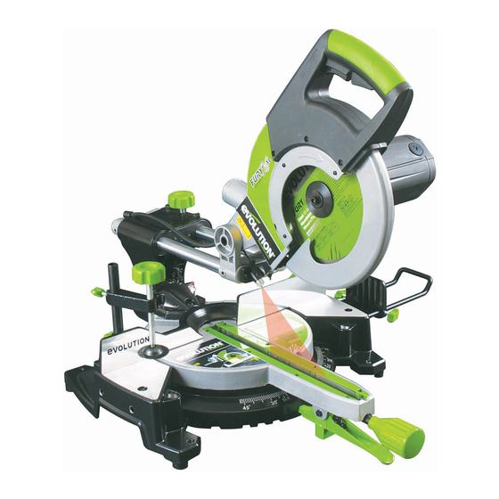
  • Seite 97: Übersicht Einzelteile

    www.evolutionpowertools.com üBERSICHT EINZELTEILE 12. Gehrungsgriff 1. Ein-/Aus-Schalter 13. Gehrungswinkelskala 2. Entriegelungsschalter Sägeblattschutz 14. Feststellhebel positiver Anschlag 3. Schneidgriff 15. werkstückstütze (optionales Zubehör) 4. Staubbeutel (optionales Zubehör) 16. Ablänganschlag (optionales Zubehör) 5. Drehtisch 17. Anschlag 6. Tischplatte 18. werkstückklemme 7. Unterer Sägeblattschutz 19.
  • Seite 98: Zusammensetzen Und Vorbereitung

    www.evolutionpowertools.com (7.1) ZUSAMMENSETZEN UND VORBEREITUNG wARNUNG: iehen Sie vor der Durchführung von Einstellungen immer den Netzstecker der Säge. Anmerkung: Es wird empfohlen, sämtliche Anweisungen immer vor der Inbetriebnahme der Säge zu lesen. (7.2) permanente Montage der Gehrungssäge Stellen Sie die Säge an die gewünschte Stelle entweder auf einer Abb.
  • Seite 99 www.evolutionpowertools.com Arm aus der Grundplatte herausgezogen werden, insbesondere, wenn die Maschine freistehend auf einer Werkbank verwendet wird. (Abb. 3). Dieser Arm sorgt für besonders gute Stabilität und verhindert, dass die Maschine im Fall eines plötzlichen Lösens des Schneidkopfs herunterfallen kann. (7.4) werkstückklemme (Abb.
  • Seite 100: Einstellung Für Laser Europäische Steckervarianten

    B. für Naturholz oder matte Oberflächen usw. • Ersetzen Sie das Lasermodul niemals durch einen Laser eines anderen Typs oder einer anderen Klasse. • Reparaturen des Lasermoduls dürfen nur von Evolution Power Tools oder einem zugelassenen Kundendienst durchgeführt werden. Wenden Sie sich dazu bitte an die erwähnte Servicestelle.
  • Seite 101: Laserstrahlung - Nicht In Den Laserstrahl Blicken Laserprodukt Der Klasse

    www.evolutionpowertools.com B. wenn der Laserstrahl parallel zu den Markierungen verläuft, jedoch nicht durch diese hindurch: • Lockern Sie die beiden Schrauben. (Abb. 7, c) • Das Lasermodul kann nun seitlich bewegt werden, um den Laserstrahl auf die Markierungen im Karton auszurichten. • Wenn sich der Laserstrahl an der richtigen Stelle befindet, die beiden Schrauben wieder anziehen.
  • Seite 102: Laserstrahlung Nicht In Den Strahl Schauen Klasse 2 Laserprodukt

    www.evolutionpowertools.com • Positionieren Sie den Karton so, dass der “Sägeblattweg”, wie er auf der Schablone markiert ist, exakt mit dem tatsächlichen Weg des Sägeblatts übereinstimmt. • Befestigen Sie die Kartonschablone in ihrer Position mit Kreppband oder dergleichen. Schalten Sie den Laser ein. • Wenn die projizierte Laserlinie exakt mit dem “Sägeblattweg” sowohl quer über den Tisch als auch in der vertikalen Achse übereinstimmt, ist nichts weiter zu tun.
  • Seite 103: Die Laserführungslinie

    www.evolutionpowertools.com wARNUNG: Blicken Sie nicht direkt in den Laserstrahl. Der Laser muss gemäss den Angaben in dieser Gebrauchsanweisung verwendet und gewartet werden. Richten Sie den Laserstrahl niemals auf Personen und vermeiden Sie es, den Strahl auf Augen oder einen anderen Gegenstand als das Werkstück zu richten.
  • Seite 104: Tiefenanschlag

    www.evolutionpowertools.com Verwendung der Laserführung für einen unbekannten winkel: • Kennzeichnen Sie den erforderlichen Schnitt mit Hilfe eines Bleistifts o.ä. auf dem Werkstück. • Legen Sie das Werkstück auf den Drehtisch und gegen den Anschlag. • Stellen Sie die Säge auf den ungefähren Schnittwinkel ein. Ziehen Sie den Feststellgriff für den Gehrungswinkel noch nicht an.
  • Seite 105: Der Obere Gleitanschlagabschnitt

    www.evolutionpowertools.com Verwendung des Tiefenanschlags: • Setzen Sie die “”Stoppplatte”” (a) des Tiefenanschlags ein, indem Sie sie ganz nach links schieben. • Lösen Sie die sperrende Flügelmutter. (b) • Justieren Sie die Rändelschraube (c), um die Bewegung des Sägekopfs auf die erforderliche Tiefe zu begrenzen. • Wenn die gewünschte Tiefe eingestellt ist, ziehen Sie die Flügelmutter (a) gegen den Haltebügel fest, um den Tiefenanschlag zu arretieren, und stellen Sie sicher, dass keine Bewegung mehr möglich ist.
  • Seite 106: Körper- Und Handpositionierung

    www.evolutionpowertools.com Stellen Sie sicher, dass der Anwender • Befestigen Sie das Werkstück fest an den angemessen im Gebrauch, der Einstellung und Tisch und gegen den Anschlag, um jede Wartung der Maschine geschult ist, bevor die Bewegung zu verhindern. Maschine an das Netz angeschlossen und die • Verwenden Sie nach Möglichkeit eine Säge in Betrieb genommen wird.
  • Seite 107: Einstellen Von Präzisionswinkeln

    www.evolutionpowertools.com (8.4) EINSTELLEN VON pRäZISIONSwINKELN Mit dieser Maschine sind mehrere Kontrollen/Einstellungen möglich. Der Anwender benötigt ein 90° 45°/45° Zeichendreieck (nicht im Lieferumfang enthalten), um diese Kontrollen und Einstellungen durchführen zu können. wARNUNG: Kontrollen/Einstellungen dürfen nur bei einer vom Netz getrennten Maschine durchgeführt werden. Abb.
  • Seite 108 www.evolutionpowertools.com • Den Neigungswinkelzeiger so einstellen, dass er präzise auf die 0° Markierung ausgerichtet ist. • Die Schraube wieder festdrehen. 45° Einstellung des Neigungswinkelanschlags • Lösen Sie den Feststellgriff für den Neigungswinkel und kippen Sie den Schneidkopf vollständig nach links, bis er gegen den 45°-Anschlag anliegt.
  • Seite 109 www.evolutionpowertools.com Falls nachjustiert werden muss: • Lösen Sie die Sperrmutter an der 33,9 -Einstellschraube. • Verwenden Sie einen Sechskantschlüssel zur Justierung der Einstellschraube einwärts oder auswärts, je nach Bedarf. (Abb. 17) • Ist eine korrekte Justierung erzielt, sperren Sie die Einstellschraube durch Festziehen der Sperrmutter. ” Ausrichten des Anschlags Der Anschlag muss auf 90° (rechtwinklig) ausgerichtet werden Der Drehtisch muss auf den Gehrungswinkel ‘0°’...
  • Seite 110: Vorbereiten Eines Schnitts

    www.evolutionpowertools.com (8.5) (Schritte VORBEREITEN EINES SCHNITTS 1 und 2) NEHMEN SIE EINE SICHERE ARBEITSpOSITION EIN. Sorgen Sie für sicheren Stand und Gleichgewicht. Stellen Sie sich seitlich, damit sich Ihr Gesicht und Körper ausserhalb der Linie eines möglichen Rückschlags befinden. Freihändiges Sägen ist eine Hauptursache für Unfälle und ist nicht zulässig.
  • Seite 111: Ein-Aus-(Usa-Modell)

    www.evolutionpowertools.com EIN-AUS-(USA-MODELL) (Abb. 22) Um die Maschine zu starten, drücken Sie den Sperrknopf für die Ein / Aus-Schalter (1) und drücken Sie dann die Ein / Aus-Schalter (2) und halten Sie sie gedrückt. Zum Ausschalten der Maschine, lassen Sie die Ein / Aus-Schalter (2). (Abb. 22). Hinweis: Aus Gründen der Sicherheit, der Ein / Aus-Schalter (2) nicht gesperrt werden kann, muss sie während gedrückt bleiben der gesamte Vorgang.
  • Seite 112 www.evolutionpowertools.com SCHIEBESCHNITT Diese Säge ist mit einem Schiebeschlitten ausgerüstet. Durch das Lösen der Schlittenverriegelungsschraube wird der Schlitten freigegeben und dadurch dem Schneidkopf ermöglicht, vor- und zurückzufahren. (Abb. 26) Das Sägeblatt senkt sich in das Werkstück und wird dann zum hinteren Teil der Maschine gedrückt, um den Schnitt fertigzustellen.
  • Seite 113 www.evolutionpowertools.com GEHRUNGSSCHNITTE (Abb. 29) Der Drehtisch dieser Maschine ist aus seiner normalen (0°) Position um 45° nach links oder rechts drehbar. Positive Anschläge sind bei 45°, 30°, 22,5° und 15° vorgesehen, und zwar sowohl auf der rechten wie auf der linken Seite. Gehrungsschnitte sind mit oder ohne Einsatz des Schlittensystems möglich.
  • Seite 114: Neueinstellung

    www.evolutionpowertools.com Schneidkopf nach links neigen: • Den Feststeller für den Neigungswinkel lösen. (Abb. 33) • Den Schneidkopf in den erforderlichen Winkel neigen. Als Hilfe für die Einstellung ist eine Winkelskala angebracht. (Abb. 34) • Den Feststeller für den Neigungswinkel anziehen, wenn der gewünschte Winkel ausgewählt worden ist.
  • Seite 115: Schneiden Von Gebogenem Material

    www.evolutionpowertools.com (8.7) KOMBISCHNITTE (Abb. 36) Ein Kombischnitt ist ein gleichzeitiger Gehrungs- und Neigungsschnitt. Wenn ein Kombischnitt erforderlich ist, die gewünschten Neigungs- und Gehrungspositionen gemäss den obigen Beschreibungen auswählen. Ein Kombischnitt mit Einsatz des Schlittensystems ist möglich. Abb. 36 Achten Sie immer darauf, dass das geschobene Sägeblatt nicht den Anschlag der Maschine oder andere Maschinenteile behindert.
  • Seite 116: Einsetzen Oder Entfernen Eines Sägeblatts

    ACHTUNG: Führen Sie diesen Vorgang nur aus, wenn die Maschine vom Stromnetz getrennt ist. ACHTUNG: Verwenden Sie nur Original-Evolution-Sägeblätter oder jene Blätter, die von Evolution Power Tools speziell empfohlen und für diese Maschine entworfen sind. Stellen Sie sicher, dass die maximale Drehzahl des Blatts höher als die Drehzahl des Motors ist.
  • Seite 117: Optionale Zubehörteile

    Herstelleranweisungen verwendet werden. ” Abb. 41 (8.12) OpTIONALE ZUBEHöRTEILE Wird nicht mit der Originalausrüstung mitgeliefert. Alle Zubehörteile können bei Evolution Power Tools gekauft werden. Siehe Abschnitt „Zusätzliche Zubehörteile“. (8.13) STAUBBEUTEL Der Staubbeutel kann an den Absaugstutzen auf der Rückseite der Maschine angebracht werden.
  • Seite 118: Ablänganschlag

    www.evolutionpowertools.com • Die Enden der Werkstück-Stützen in die Halteöffnungen in der Grundplatte stecken. Um einen festen Sitz sicherzustellen, vollständig nach innen drücken. Hinweis: Ca. 75 mm der Stützenstange müssen in die Grundplatte geschoben werden, um einen festen Sitz zu garantieren. • Die Halteschraube festdrehen.
  • Seite 119: Sicherheitsendkontrolle

    www.evolutionpowertools.com SICHERHEITSENDKONTROLLE Zustand Gleitschienen In den Schlitten eingeschoben und am Schneidkopf befestigt. Positionierstifte erfolgreich eingesetzt. Feststellhebel positiver Am Feststellmechanismus montiert. Anschlag Feststellgriff für den An der Feststellschraube montiert. Gehrungswinkel Netzkabel Korrekt verlegt und an der hinteren Schiebehalterung befestigt. Max. 50 – 60 mm Durchbiegung am Mittelpunkt. Sägeblatt Sägeblatt mit übereinstimmenden Drehrichtungspfeilen montiert.
  • Seite 120: Wartung

    www.evolutionpowertools.com wARTUNG Tischeinsatz Ein zweiteiliger Tischeinsatz ist an der Maschine befestigt. Sollte eine der beiden Teile beschädigt Hinweis: Wartungsarbeiten dürfen nur bei oder abgenutzt sein, müssen beide Teile ersetzt ausgeschalteter Maschine und vom Netz/von werden. Ersatzeinsätze (nur paarweise) sind bei der Batterie getrennt durchgeführt werden.
  • Seite 121: Umweltschutz

    www.evolutionpowertools.com (6.4) UMwELTSCHUTZ Entsorgung von Elektrogeräten Elektrische und elektronische Altgeräte enthalten vielfach noch wertvolle Materialien. Sie enthalten aber auch schädliche Stoffe, die für ihre Funktion und Sicherheit notwendig waren. Im Restmüll oder bei falscher Behandlung können diese der menschlichen Gesundheit und der Umwelt schaden.
  • Seite 122: Eg-Konformitätserklärung

    EG-KONFORMITäTSERKLäRUNG Der Hersteller des von dieser Erklärung behandelten produkts ist: Evolution Power Tools Ltd. Venture One, Longacre Close, Holbrook Industrial Estate, Sheffield, S20 3FR. Der Hersteller erklärt hiermit, dass die Maschine wie in dieser Erklärung angegeben alle relevanten Bestimmungen der Maschinenrichtlinie und andere einschlägige Richtlinien wie unten angegeben erfüllt.
  • Seite 123 EG-KONFORMITäTSERKLäRUNG Der Hersteller des von dieser Erklärung behandelten produkts ist: Evolution Power Tools Ltd. Venture One, Longacre Close, Holbrook Industrial Estate, Sheffield, S20 3FR. Der Hersteller erklärt hiermit, dass die Maschine wie in dieser Erklärung angegeben alle relevanten Bestimmungen der Maschinenrichtlinie und andere einschlägige Richtlinien wie unten angegeben erfüllt.
  • Seite 125 ITALIANO Traduzione di manuali di istruzioni originali...
  • Seite 126 www.evolutionpowertools.com INDICE SpECIFICHE MACCHINA Introduzione Garanzia Vibrazioni Destinazione d'uso di questo strumento di potere Uso vietato di questo strumento di potere MISURE DI SICUREZZA Sicurezza elettrica Generali Power Tool Istruzioni di sicurezza Consigli salute Specifiche istruzioni di sicurezza Dispositivi di Protezione Individuale (DPI) Funzionamento sicuro Aditional Consigli di sicurezza pER INIZIARE...
  • Seite 127 www.evolutionpowertools.com...
  • Seite 128: Specifiche Macchina

    www.evolutionpowertools.com 210mm TCT MULTIpURpOSE SCORREVOLI TRONCATRICI Specifiche Metric Imperial progettato per tagliare Mild Steel Plate - Spessore max 1/8” Acciaio dolce Box Sezione - Max Spessore parete 1/8” Legno - Sezione max 60mm x 220mm 2-3/8” x 8-3/4” Motore (230-240V~ 50Hz) 1500W Nessun velocità...
  • Seite 129 www.evolutionpowertools.com STEALTH 255mm TCT MULTIpURpOSE SCORREVOLI TRONCATRICI Specifiche Metric Imperial progettato per tagliare Mild Steel Plate - Spessore max 1/8” Acciaio dolce Box Sezione - Max Spessore parete 1/8” Legno - Sezione max 75mm x 300mm 3” x 11-3/4” Motore (230-240V~ 50Hz) 2000W Nessun velocità...
  • Seite 130: Introduzione

    A4 volantino di elenco non esaustivo) lame, frese , trapani, registrazione incluso in questo macchina. scalpelli o pagaie ecc In nessun caso Evolution È anche possibile eseguire la scansione Power Tools saranno responsabili per perdite o...
  • Seite 131: Vibrazioni

    In danneggiate. Rivolgersi a Evolution Power presenza di uno dei suddetti sintomi è necessario Tools per la sostituzione delle etichette.
  • Seite 132: Destinazione D'uso Di Questo Strumento Di Potere

    All’interno del prodotto non sono presenti di trazione, appositamente studiata per componenti sostituibili da parte dell’utente, l’utilizzo con lame di taglio multiuso Evolution. fatta eccezione per quelli indicati nelle presenti Utilizzare esclusivamente lame di taglio istruzioni d’uso. Far sempre eseguire gli interventi...
  • Seite 133: Generali Power Tool Istruzioni Di Sicurezza

    www.evolutionpowertools.com AVVERTENZA: Avvertenza! Leggere tutte le • Non esporre gli utensili elettrici alla pioggia né utilizzarli in ambienti umidi. La avvertenze e le istruzioni di sicurezza. In caso di mancato rispetto delle avvertenze e istruzioni penetrazione d’acqua in un utensile elettrico sussiste il pericolo di scosse elettriche, aumenta il rischio di scosse elettriche.
  • Seite 134 www.evolutionpowertools.com • Evitare l’accensione accidentale • Non utilizzare l’utensile elettrico se dell’utensile. Prima di collegare l’utensile l’interruttore di accensione/ spegnimento non funziona correttamente. Un utensile alla fonte di alimentazione e/o alla batteria, durante il sollevamento o durante il elettrico che non è più attivabile/disattivabile trasporto dell’utensile, accertarsi che correttamente è...
  • Seite 135: Avvertenze Di Sicurezza Specifiche Per L'utilizzo Della Sega Per Tagli Obliqui

    www.evolutionpowertools.com (2.6) (3.5) AVVERTENZE DI SICUREZZA 5) Avvertenze di sicurezza generali SpECIFICHE pER L’UTILIZZO DELLA [manutenzione] per utensili elettrici SEGA pER TAGLI OBLIQUI • Far riparare l’utensile elettrico esclusivamente da personale qualificato. In tal modo viene garantita la sicurezza a Le seguenti avvertenze di sicurezza specifiche lungo termine dell’utensile elettrico.
  • Seite 136: Dispositivi Di Protezione Individuale (Dpi)

    www.evolutionpowertools.com (3.6) caso di sega per tagli obliqui con funzione di DISpOSITIVI DI pROTEZIONE trazione il trasporto va eseguito mediante le INDIVIDUALE (DpI) maniglie in dotazione). La macchina non deve mai essere sollevata o trasportata mediante il È obbligatorio indossare protezioni auricolari paralama inseribile o tramite altri elementi di per evitare il rischio di deficit uditivi causati tale meccanismo di azionamento.
  • Seite 137: Aditional Consigli Di Sicurezza

    www.evolutionpowertools.com Prima di ogni taglio assicurarsi sempre che la schiena. Sollevare l’utensile utilizzando le sega per tagli obliqui sia stata montata in una apposite maniglie presenti su entrambi i lati posizione stabile. sulla piastra di base della macchina. • Non trasportare mai la sega afferrandola Se necessario, la sega per tagli obliqui, in dal cavo di alimentazione.
  • Seite 138: Accessori Opzionali

    Per il sollevamento, il montaggio e il trasporto Componente Descrizione della presente macchina possono essere n° necessarie due persone. Montare la macchina DIAMOND210 Evolution mediante gli accessori in dotazione, Diamond Blade presenti nell’imballaggio. DIAMOND255 Contenitore di raccolta EV3S174 o Controllare attentamente se la macchina...
  • Seite 139: Panoramica Della Macchina

    www.evolutionpowertools.com pANORAMICA DEI SINGOLI COMpONENTI 12. Impugnatura per taglio obliquo 1. Interruttore ON/OFF 13. Scala angolare graduata per taglio obliquo 2. Interruttore di sbloccaggio del paralama 14. Leva di arresto per fermo di battuta 3. Impugnatura di taglio 15. Porta-pezzo da lavorare 4.
  • Seite 140: Montaggio E Preparazione

    www.evolutionpowertools.com (7.1) MONTAGGIO E pREpARAZIONE AVVERTENZA: Prima di eseguire regolazioni estrarre sempre la spina di rete della sega. Nota: Si raccomanda di leggere sempre tutte le istruzioni prima della messa in funzione della sega. (7.2) Montaggio permanente della sega per tagli obliqui Collocare la sega nella posizione desiderata su un banco di lavoro Fig.
  • Seite 141 www.evolutionpowertools.com Se l’apparecchio ne è opportunamente equipaggiato, è necessario estrarre il braccio dal pannello di base, in particolare se la macchina viene utilizzata a posizionamento libero sul banco di lavoro. (Fig. 3). Tale braccio garantisce una stabilità ottimale e impedisce che la macchina possa cadere in caso di improvviso distacco della testina di taglio.
  • Seite 142 • Non sostituire mai il modulo laser con un laser di tipo diverso o di una classe differente. • Le riparazioni del modulo laser devono essere eseguite (a)(b) esclusivamente da Evolution Power Tools o da un servizio clienti autorizzato. Fig. 6 REGOLAZIONE LASER PER MODELLI SpINA EUROpEA AVVERTENZA: Durante la procedura di regolazione il motore non deve mai essere avviato.
  • Seite 143 www.evolutionpowertools.com B. Se la traiettoria del raggio laser è parallela ai contrassegni, ma non passa attraverso i contrassegni: • Allentare le due viti. (Fig. 7, c) • A questo punto il modulo laser può essere movimentato lateralmente per allineare il raggio laser ai contrassegni. • Quando il raggio laser si trova nel punto corretto, avvitare nuovamente le due viti. • Ripetere la procedura ‘A’ per controllare nuovamente l’allineamento.
  • Seite 144 www.evolutionpowertools.com per controllare l’allineamento del laser: • Sistemare la mascherina in cartone per il laser (in dotazione) sul piano rotante (Fig. 8c). • Abbassare la testa di taglio e tracciare il percorso della lama attraverso la mascherina facendo scorrere avanti e indietro la testa di taglio. • Posizionare il cartone in modo che il percorso della lama segnato sulla mascherina corrisponda esattamente con l’effettivo percorso della lama. • Fissare la mascherina di cartone in posizione usando nastro di carta o simili.
  • Seite 145: Sicurezza Laser

    www.evolutionpowertools.com SICUREZZA LASER Il dispositivo guida-laser impiegato nel presente prodotto utilizza un laser di classe 2 con una potenza massima in uscita di 1,5 mW e una lunghezza d’onda compresa tra 635 e 670 nm. Tali raggi laser non causano normalmente danni ottici, ma fissare il raggio può...
  • Seite 146 www.evolutionpowertools.com Utilizzo della guida laser per un’angolazione sconosciuta: • Contrassegnare il taglio necessario mediante un pennarello o simile sul pezzo da lavorare. • Posizionare il pezzo da lavorare sulla tavola rotante e contro la battuta. • Regolare la sega all’angolazione di taglio approssimativa. Non serrare ancora l’impugnatura di arresto per l’angolo obliquo. • Spostare lentamente il pezzo da lavorare avanti e indietro lungo la battuta e contemporaneamente impostare l’angolazione della tavola rotante. • Fermarsi quando la linea laser proiettata e la linea tracciata a Fig.
  • Seite 147: Istruzioni Per L'uso

    www.evolutionpowertools.com • Allentare il galletto di blocco (b). • Regolare la vite zigrinata (c) in modo da limitare la corsa della testa di taglio alla profondità richiesta. • Una volta ottenuta la profondità desiderata, stringere il galletto (a) contro la staffa di trattenuta in modo da bloccare il fermo di profondità e assicurare l’assenza di movimento. • Dopo aver completato il taglio, regolare di nuovo il fermo di profondità...
  • Seite 148 www.evolutionpowertools.com Confrontare la freccia della direzione di • Evitare movimenti sfavorevoli e movimenti rotazione presente sul paralama con la freccia delle mani in cui le dita o una mano possano di direzione presente sulla lama di taglio. I denti finire a contatto con la lama di taglio in caso della lama di taglio nella parte anteriore della di slittamento improvviso.
  • Seite 149 www.evolutionpowertools.com ANGOLO DI INCLINAZIONE (0° E 45°) Regolazione a 0° della battuta dell’angolo di inclinazione • Accertarsi che la testina di taglio si trovi sempre nella posizione di bloccaggio più bassa e che il perno di arresto sia completamente scattato in posizione. (vedi Fig. 19) • Accertarsi che la testina di taglio poggi verticalmente contro la rispettiva battuta e che l’indicatore dell’angolo di inclinazione indichi sulla scala graduata 0°.
  • Seite 150 www.evolutionpowertools.com Regolazione a 45° della battuta dell’angolo di inclinazione • Allentare l’impugnatura di arresto dell’angolo di inclinazione e ribaltare completamente la testina di taglio verso sinistra finché poggia contro la battuta di 45°. • Verificare mediante la squadra graduata se la lama di taglio si trova a un’angolazione di 45° rispetto al tavolo (non collocare la squadra graduata sulle punte TCT). • Se la lama di taglio non è allineata in modo preciso, è...
  • Seite 151 www.evolutionpowertools.com Allineamento della battuta • La battuta deve essere allineata a 90° (angolo retto) • La tavola rotante deve essere regolata a un angolo obliquo di ‘ 0°’ . • La battuta è fissata mediante due viti a brugola, situate su entrambi i lati della battuta in fessure allungate. (Fig.18) • Accertarsi che la testina di taglio si trovi sempre nella posizione di bloccaggio più bassa e che il perno di arresto sia completamente scattato in posizione. • Posizionare la squadra graduata sul tavolo, facendo in modo che l’estremità...
  • Seite 152 www.evolutionpowertools.com • Non utilizzare la presente macchina per tagliare pezzi di fasi 1 e 2 piccole dimensioni. Se la mano o il dito si trova a distanza inferiore di 150 mm dalla lama di taglio, il pezzo da lavorare è troppo piccolo. SBLOCCAGGIO E SOLLEVAMENTO DELLA TESTINA DI TAGLIO (Fig.
  • Seite 153 www.evolutionpowertools.com La slitta deve essere bloccata nella posizione più arretrata possibile. (Fig. 23) • Spostare la testina di taglio il più possibile all’indietro. • Serrare nuovamente a fondo la vite di bloccaggio della slitta. (Fig. 24) • Collocare il pezzo da lavorare sul tavolo e contro la battuta e fissarlo mediante una/più morse a seconda della necessità. • Afferrare la maniglia della sega. • Accendere il motore e attendere che la lama di taglio abbia raggiunto la massima velocità. • Premere il dispositivo di bloccaggio di sicurezza inferiore per Fig.
  • Seite 154: Tagli Obliqui

    www.evolutionpowertools.com • Premere il dispositivo di bloccaggio di sicurezza inferiore per rilasciare la testina di taglio. • Premere la testina di taglio completamente verso il basso e tagliare il bordo anteriore del pezzo. • Spingere attentamente l’impugnatura di taglio all’indietro fino alla battuta e terminare il taglio. • A ogni passaggio spingere sempre completamente la testina di taglio all’indietro. (Fig. 28) • Una volta terminato il taglio, rilasciare l’interruttore ON/OFF e attendere che la lama di taglio si sia fermata completamente. • Attendere che la testina di taglio abbia raggiunto la posizione Fig.
  • Seite 155 www.evolutionpowertools.com TAGLI ANGOLARI – INCLINAZIONE DELLA TESTINA DI TAGLIO Un taglio angolare (Fig. 32) viene eseguito mediante la tavola rotante impostata su un angolo obliquo di 0°. Nota: La sezione superiore della battuta deve eventualmente essere adeguata per creare una distanza per il movimento della testina di taglio.
  • Seite 156 www.evolutionpowertools.com MODANATURA Sganciare la spina di modanatura: • Estrarre leggermente la spina verso l’esterno. • Ruotare la spina di 1/4 di giro (fig. 35). • Lasciare che la spina si porti sulla sua posizione interna (con impegno). Inclinare la testa di taglio alla posizione di modanatura a 33,9° e stringere la manopola di blocco della molatura. Fig. 35 Assicurare il corretto posizionamento per la modanatura sul piano rotante prima di eseguire il taglio.
  • Seite 157 AVVERTENZA: Eseguire questa operazione esclusivamente con la macchina scollegata dall’alimentazione di rete. AVVERTENZA: Usare esclusivamente lame Evolution oppure lame specificamente raccomandate da Evolution Power Tools e Fig. 39 progettate per questo apparecchio. Assicurarsi che la velocità massima della lama sia maggiore della velocità...
  • Seite 158: L'utilizzo Di Accessori Aggiuntivi

    (8.12) UTILIZZO DI ACCESSORI OpZIONALI Non in dotazione con l’equipaggiamento originale. Tutti gli accessori possono essere acquistati presso Evolution power Tools. Vedi paragrafo “Accessori supplementari” . (8.13) SACCO RACCOGLI-pOLVERE Il sacco raccogli-polvere può essere applicato al bocchettone di aspirazione sul retro della macchina.
  • Seite 159 www.evolutionpowertools.com Nota: Per mantenere le massime prestazioni, svuotare il sacco raccogli-polvere quando è riempito per 2/3. Smaltire il contenuto del sacco raccogli-polvere in modo compatibile con l’ambiente. Durante lo svuotamento del sacco raccoglipolvere può essere necessario indossare una maschera anti-polvere. Nota: Se necessario, è...
  • Seite 160 www.evolutionpowertools.com GUIDA LONGITUDINALE (Fig. 43) L’utilizzo della guida longitudinale può essere molto utile per l’utente quando si eseguono tagli ripetitivi. Se devono essere tagliati molti pezzi di materiali, tutti della stessa lunghezza, la guida longitudinale contribuisce a garantire maggiore precisione ed efficienza. Installazione della guida longitudinale • Allentare le manopole di arresto della guida longitudinale in modo che le barre del porta-pezzo possano scorrere...
  • Seite 161: Finale Safety Check List

    www.evolutionpowertools.com CONTROLLO DI SICUREZZA FINALE Stato Sì Inserite nelle slitte e fissate alla testina di taglio. Guide di scorrimento Perni di posizionamento correttamente inseriti. Leva di arresto per Montata sul meccanismo di arresto. fermo di battuta Impugnatura di arresto Montata sulla vite di arresto. dell’angolo obliquo Posizionato correttamente e fissato al supporto Cavo di rete...
  • Seite 162: Manutenzione

    Evolution Power Tools. correttamente. Utilizzare la macchina solo se tutti i dispositivi di protezione/sicurezza sono Sostituzione degli inserti del tavolo: completamente pronti per l’uso.
  • Seite 163: Protezione Ambientale

    www.evolutionpowertools.com pER GLI UTENTI AZIENDALI ( 6.4 ) pROTEZIONE AMBIENTALE NELL’UNIONE EUROpEA Rifiuti prodotti elettrici non devono essere Se desiderate eliminare apparecchiature elettriche smaltiti con i rifiuti domestici . Riciclare ed elettroniche, contattare il rivenditore o il dove esistono strutture. Verificare con fornitore per ulteriori informazioni .
  • Seite 164: Dichiarazione Di Conformita 'Ce

    DICHIARAZIONE DI CONFORMITA ‘CE Il fabbricante del prodotto oggetto della presente dichiarazione è: Evolution Power Tools, Venture One, Longacre Vicino, Holbrook Industrial Estate, Sheffield, S20 3FR. Il costruttore dichiara che la macchina come descritto nella presente dichiarazione soddisfa tutte le pertinenti disposizioni della direttiva macchine e altre direttive utili come di seguito dettagliato.
  • Seite 165 DICHIARAZIONE DI CONFORMITA ‘CE Il fabbricante del prodotto oggetto della presente dichiarazione è: Evolution Power Tools, Venture One, Longacre Vicino, Holbrook Industrial Estate, Sheffield, S20 3FR. Il costruttore dichiara che la macchina come descritto nella presente dichiarazione soddisfa tutte le pertinenti disposizioni della direttiva macchine e altre direttive utili come di seguito dettagliato.
  • Seite 167 NEDERLANDS Vertaling van de originele gebruiksaanwijzing...
  • Seite 168 www.evolutionpowertools.com INHOUDSOpGAVE mACHINE SPECIFICATIE Introductie Garanderen Vibratie Beoogd gebruik van deze Power Tool Verboden gebruik van deze Power Tool VEILIgHEID Elektrische veiligheid Algemeen Power Tool veiligheidsinstructies Gezondheid Advies Specifieke veiligheidsinstructies Persoonlijke beschermingsmiddelen (PBM) Veilig werken Extra veiligheid Advies AAN DE SLAg Uitpakken Extra accessoires Machine Overzicht...
  • Seite 169 www.evolutionpowertools.com...
  • Seite 170: Machine Specificatie

    www.evolutionpowertools.com 210mm TCT MULTIpURpOSE SLIDING MITRE ZAGEN Specificatie Metrisch Engels Ontworpen om dwars Mild Steel Plate - Max Dikte 1/8” Mild Steel Sectie Box - Max Wanddikte 1/8” Hout - Max Sectie 60mm x 220mm 2-3/8” x 8-3/4” Motor (230-240V~ 50Hz) 1500W Onbelast toerental 3750min...
  • Seite 171 www.evolutionpowertools.com STEALTH 255mm TCT MULTIpURpOSE SLIDING MITRE ZAGEN Specificatie Metrisch Engels Ontworpen om dwars Mild Steel Plate - Max Dikte 1/8” Mild Steel Sectie Box - Max Wanddikte 1/8” Hout - Max Sectie 75mm x 300mm 3” x 11-3/4” Motor (230-240V~ 50Hz) 2000W Onbelast toerental 2500min...
  • Seite 172: Introductie

    Evolutions website uit het gebruik maken van onze merchandise te valideren door het invoeren van uw of van enige andere oorzaak . Evolution Power gegevens en dus een snelle service Tools is niet aansprakelijk voor eventueel verzekeren indien ooit nodig .
  • Seite 173: Vibratie

    Neem contact op met Evolution Power Tools in de gaten houden. Indien een van deze voor vervangende labels. symptomen optreden, moet u onmiddellijk een dokter raadplegen.
  • Seite 174: Beoogd Gebruik Van Deze Power Tool

    Als het snoer beschadigd speciale veelzijdige zaagbladen van Evolution. is, moet het worden vervangen door een Gebruik alleen zaagbladen ontworpen voor speciale kabel of set beschikbaar bij de deze machine en/of specifiek aanbevolen door fabrikant of zijn vertegenwoordiger.
  • Seite 175 www.evolutionpowertools.com (2.1) Elektrische gereedschappen maken vonken en ALGEMENE kunnen het stof of de dampen doen ontvlammen. VEILIGHEIDSINSTRUCTIES VOOR c) Houd kinderen en omstanders uit de ELEKTRISCH GEREEDSCHAp buurt tijdens het bedienen van elektrisch gereedschap. Afleidingen kunnen toe leiden (Deze algemene veiligheidsinstructies zijn dat u de controle verliest.
  • Seite 176 www.evolutionpowertools.com (2.4) Het gebruik van stofverzameling kan gevaren 3) Algemene veiligheidswaarschuwingen gerelateerd aan stof verminderen. voor elektrisch gereedschap Waarschuwingen [Persoonlijke veiligheid] (2.5) 4) Algemene veiligheidswaarschuwingen a) Blijf alert, let op wat je doet en gebruik uw gezonde verstand bij het bedienen van een voor elektrisch gereedschap elektrisch gereedschap.
  • Seite 177: Gezondheid Advies

    www.evolutionpowertools.com (3.5) gemakkelijker te bedienen en lopen minder SpECIFIEKE VEILIGHEID VOOR vaak vast. VERSTEKZAGEN g) gebruik het elektrische gereedschap, de accessoires en inzetgereedschappen etc., in overeenstemming met deze De volgende specifieke veiligheidsinstructies instructies, rekening houdende met de voor verstekzagen zijn gebaseerd op de werkomstandigheden en het werk dat moet vereisten van EN61029-2-9:2009.
  • Seite 178: Veilige Bediening

    www.evolutionpowertools.com Bescherming van de ademhalingsorganen snelheidsmarkering op het zaagblad ten minste wordt ook aanbevolen, aangezien sommige gelijk is aan de snelheid zonder belasting hout- en houtsoortproducten, met name aangegeven op de verstekzaag. Onder geen MDF (Medium-density fibreboard), stof enkele omstandigheid mag u een zaagblad kunnen produceren dat schadelijk voor uw gebruiken, ontworpen voor een snelheid gezondheid kan zijn.
  • Seite 179: Aan De Slag - Uitpakken

    www.evolutionpowertools.com (2.8) • Voordat u de verstekzaag beweegt, WAARSCHUWINg: de werking van een moet u de vergrendelingschroeven verstekzaag kan er toe leiden dat er voorwerpen voor het verstek- en schuinzagen richting uw ogen worden geschoten, wat kan en de vergrendelingschroef van het leiden tot ernstige oogschade.
  • Seite 180: Optionele Accessoires

    Hiertoe behoren de volgende artikelen: Recycle indien mogelijk. Laat kinderen niet met de lege plastic zakjes spelen, in verband Beschrijving part N° met verstikkingsgevaar. DIAMOND210 Evolution (4.2) Diamond Blade MEEGELEVERDE ARTIKELEN DIAMOND255 EV3S174 or Stofopvangzak • Instructies SR3S174 • Vastzetklem...
  • Seite 181: Machine Overzicht

    www.evolutionpowertools.com ALGEMEEN OVERZICHT VAN VERSTEKZAAG ACHTERZIjDE VAN MACHINE 13. HoEKSCHAAL VERSTEK zAgEN 1. AAN/UIT-TREKKERSCHAKELAAR 14. VERgRENDELHENDEL VooRINgESTELDE 2. VERgRENDELTREKKER BESCHERmKAP SToP 3. zAAgHANDVAT 15. WERKSTUKACCESSoIRE 4. SToFzAK (optioneel accessoire) (optioneel accessoire) 5. DRAAIENDE TAFEL 16. HERHAALSToP (optioneel accessoire) 6. TAFELBLAD 17.
  • Seite 182: Montage En Voorbereiding

    www.evolutionpowertools.com (7.1) MONTAGE EN VOORBEREIDING WAARSCHUWINg: Ontkoppel altijd de voeding naar de zaagmachine voordat u eventuele aanpassingen aanbrengt. opmerking: Het is aanbevolen dat alle instructies altijd gelezen worden voor gebruik. (7.2) pERMANENTE MONTAGE VAN DE VERSTEKZAAG Afb. 1 Om het risico op letsel door het onverwachts starten van 1) Schroef met zeskantkop zaagbeweging te verminderen, plaats de zaag op de gewenste 2) Veerring...
  • Seite 183 www.evolutionpowertools.com opmerking: Sommige machines zijn voorzien van een stabilisatiearm aan de achterkant, vlak onder de spil voor het schuin zagen. Indien deze arm gemonteerd is, moet hij ingezet worden/uit het voetstuk gehaald worden, voornamelijk wanneer de machine los op de werkbank zal worden gebruikt. (Afb. 3) Deze arm zal extra stabiliteit leveren om te voorkomen dat de machine kantelt indien de zaagkop plotseling vrijkomt.
  • Seite 184 • Vervang de lasermodule nooit voor een andere type laserklasse. • Reparaties aan de lasermodule mogen alleen uitgevoerd worden door Evolution Power Tools of hun geautoriseerde (a)(b) vertegenwoordigers. Afb. 6...
  • Seite 185 www.evolutionpowertools.com • Het montageblok van de laser kan nu opzij bewogen worden om de laserstraal op de markeringen af te stemmen. • Draai de twee schroeven opnieuw vast wanneer de laserstraal zich op de juiste plaats bevindt. • Herhaal procedure “A” om de uitlijning te controleren. opmerking: De hierboven beschreven aanpassingen en uitlijning moet regelmatig gecontroleerd worden om de nauwkeurigheid van de laser te verzekeren.
  • Seite 186 www.evolutionpowertools.com Schakel de laser in. • Wanneer de geprojecteerde laserlijn exact overeenkomt met de ‘baan van het blad’ zowel over de tafel als ook in de verticale as, hoeft er verder niets gedaan te worden. De geprojecteerde laserlijn is niet verticaal : • Draai de kruiskopschroef los en draai de lasermodule voorzichtig in zijn montageblok tot de laserlijn verticaal is. • Draai de schroef opnieuw vast en controleer opnieuw.
  • Seite 187 www.evolutionpowertools.com eenheid alleen aan voor het maken van afstellingen. Reparaties aan de laser mogen alleen uitgevoerd worden door een geautoriseerd onderhoudscentrum. De laserbegeleidingslijn De geprojecteerde laserbegeleidingslijn toont het pad van het zaagblad tijdens de snede. Om de laserbegeleiding bij een bekende hoek te gebruiken (bijv.
  • Seite 188 www.evolutionpowertools.com Trek voorzichtig de lens van de lasereenheid en vervang deze voor een nieuwe lens. DIEpTESTOp (Afb. 9) Gebruik van de dieptestop geeft de operator de mogelijkheid om gleuven in het werkstuk te zagen. De neerwaartse beweging van de zaagkop kan ingesteld worden zodat het zaagblad niet volledig door het werkstuk zaagt.
  • Seite 189: Gebruiksaanwijzing

    www.evolutionpowertools.com Voor het aanpassen van het hek: (8.2) WAARSCHUWINg: • Maak de duimschroef los. (Afb. 10) Om het risico op letsel • Schuif het bovengedeelte van het hek naar te verminderen, moet u altijd de stekker uit het links naar de gewenste positie en draai de stopcontact halen voordat u machineonderdelen duimschroef opnieuw aan.
  • Seite 190 www.evolutionpowertools.com • Vermijd onhandige handelingen en handposities, waarbij een onverwachtse beweging uw vingers of handen in het zaagblad terecht kunnen doen komen. • Voordat u een snede gaat maken, voer eerst een proefbeweging uit met de stroom uit, zodat u het pad van het zaagblad kunt zien.
  • Seite 191 www.evolutionpowertools.com Afstelling afschuiningwijzer 0° oPmERKINg: De operator moet overtuigd zijn dat het zaagblad loodrecht op de tafel staat wanneer deze zich in de bovenpositie tegen zijn stop bevindt. • Indien de wijzer niet precies uitgelijnd is met de 0° markering van de hoekmeter, is afstelling noodzakelijk.
  • Seite 192 www.evolutionpowertools.com • Schuif de noniushoekmeter op zijn plaats terwijl één arm op de draaitafel rust en de andere op het gekantelde blad rust. • Lees de hoekinstelling af. wanneer aanpassing nodig is: • Draai de borgmoer op de 33,9 stelschroef los. • Gebruik de zeskantsleutel om de stelschroef naar wens naar binnen of naar buiten bij te stellen. (Afb. 17) • Nadat de correcte instelling is bereikt, de stelschroef vergrendelen door de borgmoer vast te draaien Afb.
  • Seite 193 www.evolutionpowertools.com (8.5) Stap 1 en 2 EEN SNEDE VOORBEREIDEN REIK NIET TE VER UIT Sta stevig en in balans. Sta aan één kant zodat uw gezicht en lichaam zich buiten de zaaglijn bevinden bij mogelijke terugslag. Vrij met de hand zagen is een van de meest voorkomende oorzaken voor ongelukken en MAG NIET geprobeerd worden.
  • Seite 194 www.evolutionpowertools.com Indien het ontgrendelen lastig is: • Schud de zaagkop rustig omhoog en omlaag. • Draai op hetzelfde moment de ontgrendelpin van de kop met de klok mee en trek deze naar buiten. oPmERKINg: Wij raden u aan om de zaagkop in de onderpositie te vergrendelen met de ontgrendelpin volledig in zijn opening, wanneer de machine niet in gebruik is.
  • Seite 195 www.evolutionpowertools.com SCHUIFZAGEN Deze machine is voorzien van een schuifmechanisme. Door de schuifvergrendelschroef los te maken, is het mogelijk om de zaagkop naar voren en achteren te bewegen. (Afb. 26) Het zaagblad wordt eerst naar beneden gebracht in het werkstuk, en vervolgens naar de achterkant van de machine gebracht om de snede te voltooien.
  • Seite 196 www.evolutionpowertools.com VERSTEKZAGEN (Afb. 29) De draaiende tafel op deze machine kan 45° graden naar rechts en links gedraaid worden vanaf de normale rechte zaagpositie (0°). Er bevinden zich vooringestelde stops op 45°, 30°, 22,5° en 15° aan zowel de rechter- als linkerkant. Verstekzagen is mogelijk zowel met als zonder het schuifsysteem ingeschakeld.
  • Seite 197 www.evolutionpowertools.com Om de zaagkop naar links te kantelen: • Maak de vergrendelschroef voor schuin zagen los. (Afb. 33) • Kantel de zaagkop naar de benodigde hoek. Er is een gradenboog beschikbaar als hulpmiddel bij het instellen. (Afb. 34) • Zet de vergrendelhendel voor schuin zagen weer vast nadat de gewenste hoek geselecteerd is.
  • Seite 198: Samengesteld Zagen

    www.evolutionpowertools.com (8.7) SAMENGESTELD ZAGEN (Afb. 36) Een samengestelde snede is een combinatie van een versteksnede en een schuine snede tegelijkertijd. Wanneer u een samengestelde snede wilt uitvoeren, selecteert u de posities voor het verstek en schuin zagen zoals in de vorige stappen is beschreven.
  • Seite 199 Voer deze operatie alleen uit terwijl de machine is losgekoppeld van de netstroomvoorziening. wAARSCHUwING: Gebruik alleen oorspronkelijke Evolution- bladen of de specifiek door Evolution Power Tools aanbevolen bladen die voor deze machine zijn ontworpen. Controleer of het maximale toerental van het blad hoger is dan het toerental van de motor.
  • Seite 200: Het Gebruik Van Extra Accessoires

    (8.12) HET GEBRUIK VAN OpTIONELE EVOLUTION TOEBEHOREN Niet meegeleverd als originele apparatuur. Alle toebehoren kunnen van Evolution power Tools gekocht worden. Zie het gedeelte “Extra toebehoren” . Afb. 41 (8.13) STOFZAK Er kan een stofzak op de afzuigopening aan de achterkant van de machine geplaatst worden.
  • Seite 201 www.evolutionpowertools.com ONDERSTEUNINGSBALKEN VOOR HET wERKSTUK (Afb. 42) Ondersteuningsbalken voor het werkstuk kunnen aan beide machine van het voetstuk van de machine gebruik worden. • Rechterkant. Maak de bevestigingsschroef voor de ondersteuning, boven aan de voorkant op het voetstuk van de machine los. • Plaats de ondersteuningsbalken voor het werkstuk in de bevestigingsgaten in het voetstuk.
  • Seite 202 www.evolutionpowertools.com AFSLUITpLUG VOOR DE ExTRACTIE-OpENING (indien meegeleverd) Gebruik de afsluitplug in plaats van de stofzak bij het snijden van materiaal op staalbasis. ADApTERBUIS VOOR DE ExTRACTIE-OpENING (indien meegeleverd) Gebruik de adapterbuis voor het aansluiten van de extractie-opening van de machine op geschikte commerciële werkplaatsvacuümextractie-apparatuur (niet meegeleverd) die flenzen of inlaatopeningen hebben met een interne doorsnede van 30 mm.
  • Seite 203: Final Veiligheid Checklist

    www.evolutionpowertools.com LAATSTE VEILIGHEIDSCONTROLES Conditie Schuifstaven Door de afschuinnek geplaatst en op de zaagkop aangesloten. Locatienokken met succes ingezet Vergrendelhendel Geïnstalleerd op het vergrendelmechanisme vooringestelde stop Verstekvergrendelhendel Geïnstalleerd op de vergrendelschroef Stroomkabel Correct geleid en vastgemaakt aan achterschuifbeugel. Maximaal 50-60mm afbuiging in het middelpunt Zaagblad Zaagblad is geïnstalleerd overeenkomstig de...
  • Seite 204: Onderhoud

    Vervangende Controleer regelmatig of alle veiligheidsfuncties inzetstukken (verkocht in paren) zijn beschikbaar en beschermingen goed werken. Gebruik deze bij uw leverancier of Evolution Power Tools. machine alleen indien alle beschermingen/ veiligheidsfuncties goed werken. Om de tafelinzetstukken te vervangen: • Verwijder de 3 of 4 kruiskopschroeven...
  • Seite 205: Bescherming Van Het Milieu

    www.evolutionpowertools.com (6.4) Voor zakelijke gebruikers in de BESCHERMING Europese Unie VAN HET MILIEU Indien u elektrische en elektronische apparatuur wilt verwijdereden, neem contact Informatie (voor particulieren) over het op met uw leverancier voor extra informatie. verwijderen van afgedankte elektrische en elektronische apparatuur (AEEA) op een Informatie over verwijdering in andere ecologisch verantwoordelijke manier.
  • Seite 206: Eg Verklaring Van Conformiteit

    EG VERKLARING VAN CONFORMITEIT De fabrikant van het product dat onder deze verklaring valt is: Evolution Power Tools, Venture One, Longacre Close, Holbrook Industrial Estate, Sheffield, S20 3FR. De fabrikant verklaart hierbij dat de machine zoals beschreven in deze verklaring voldoet aan alle relevante bepalingen van de machinerichtlijn en andere relevante richtlijnen zoals hieronder be- schreven.
  • Seite 207 EC DECLARATION OF CONFORMITY De fabrikant van het product dat onder deze verklaring valt is: Evolution Power Tools, Venture One, Longacre Close, Holbrook Industrial Estate, Sheffield, S20 3FR. De fabrikant verklaart hierbij dat de machine zoals beschreven in deze verklaring voldoet aan alle relevante bepalingen van de machinerichtlijn en andere relevante richtlijnen zoals hieronder be- schreven.
  • Seite 208 Evolution Power Tools Ltd Evolution Power Tools LLC Evolution Power Tools SAS Venture One 8363 Research Drive 61 Avenue Lafontaine Longacre Close Davenport 33560 Holbrook Industrial Estate Iowa Carbon-Blanc Sheffield 52806 Bordeaux S20 3FR +44 (0)114 251 1022 +1 866-EVo-TooL...

Inhaltsverzeichnis