FLEISCHMANN 41 Serie Betriebsanleitung
Quicklinks
z
NEM
Schnittstelle/interface/connecteur NEM 651
c
b
Fig. 2
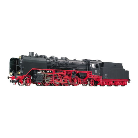
Lok mit LED-Beleuchtung.
Ein Öffnen der Lok ist nur zum Einbau eines DECODERS (DCC: 687301) erforderlich. Die Schrauben a, b und c lösen und das
Gehäuse nach oben abheben (Fig. 2).
Ölen: Geölt werden die Achsen und das Getriebe nur an den gekennzeichneten Schmierstellen (Fig. 3). Die Motor lager dürfen
unter keinen Umständen geölt werden!
Nur FLEISCHMANN-Öl 6599 verwenden. Nur ein kleiner Tropfen pro Schmierstelle (
Zur Dosierung die in der Verschlusskappe der Ölflasche angebrachte Nadel verwenden.
An der markierten Stelle kann der Schaltmagnet 942701 eingebaut werden (Fig. 3).
Der Lok liegen 2 Kolbenstangenschutzrohre bei, die Sie montieren können wenn sie die Lok auf Radien >R2 fahren lassen. Kol-
benstangenschutzrohre von vorne in die rechteckige Öffnung am Zylinder stecken (Fig. 2).
Sollte ihre Lok mit Bremsgehängen an den Vorlaufrädern ausgestattet sein, sind diese nach unten abzuziehen, wenn sie klei-
nere Radien als R2 befahren wollen.
942701
Fig. 3
Kolbenstangenschutzrohr, für Radien >R2
a
piston rod protection tube, for curves >R2
Contre-tige pour courbes >R2
), sonst Überölung.
Fig. 5
00544007
Tender mit LED-Beleuchtung.
Ein Öffnen des Tenders ist nur zum Ölen des Getriebes und
zum Austausch des Motors erforderlich.
Schrauben d, e und f lösen und das Tendergehäuse nach
oben abheben (Fig. 4).
Achtung: Wartungsfreier Motor!
Die Motorschleifkohlen sind nicht austauschbar!
Die Motor lager dürfen unter keinen Umständen geölt
werden!
Motortausch: Motorhalteklammer leicht aufbiegen und ab-
nehmen. Motor nach oben herausnehmen (Fig. 5). Beim
Einbau des neuen Motors auf die richtige Lage achten. Hierzu
die rot/schwarze Markierung an den Kohlenrohren des Mo-
tors beachten.
Tauschmotor: 00504103
Ersatzhaftreifen: 00544007
Fig. 4
NEM
Geeigneter DCC-Decoder: 687301
Die Lokomotive ist mit einer 6-poligen elektrischen Steck-
Schnitt stelle nach NEM 651 ausgestattet. Zum Einbau eines
digitalen DECODERS das Lokgehäuse abnehmen (Fig. 2). Die
Schnittstelle vorsichtig vom Untergrund lösen und den Brük-
kenstecker z herausziehen. Brückenstecker gut aufheben, er
kann bei einer Fehlersuche zum Rückbau auf Gleichstromver-
sion wieder verwendet werden. Den 6-poligen Stecker des
DCC-DECODERS so in die Schnittstel le stecken, dass die Mar-
kierungen „1" auf der gleichen Kante liegen. Bei Bedarf mit ei-
schwarz/black/noir
nem der Klebestreifen, die dem DECODER beiliegen, den DE-
CODER mit dem größten Bauelement an die Innenseite des
Messing-Metallwin kels kleben (s. Fig. 2). Beim Einkleben des
DECODERS auf den geringen Platz im Lokgehäuse achten, so
dass beim späteren Aufsetzen des Gehäuses keine Litzen ein-
geklemmt werden. Hierbei darauf achten, dass DECODER
und Schnittstelle durch das Klebeband elektrisch vom
Metallwinkel isoliert sind (Kurzschlussgefahr!). Lokgehäuse
wieder aufsetzen und mit den Schrau ben a, b, c befestigen.
Die Lok kann nun unter der Adresse „3" fahren.
Class 41 with variants
Between 1936 and 1941, a total of 366 engines of the Class 41 were built. They were used as a mixed traffic loco, which, with a top
speed of 90 km/h and a power rating of 1900 Hp, could also haul fast expresses, even though they were originally intended for use
pulling fast goods trains. Because the first locos were used to pull fast cattle trains, they became known as the »Oxen-Locos«. The slim
boiler and well proportioned driving mechanism gave her an elegant appearance.
Due to the reason that time and again technical difficulties occured with the boilers that were very susceptible to damage, the DR (OST)
had to take 300 locomotives out of service in 1956. This led to an enormous shortage of locomotives. The newly emerged need for trade
prompted the development and consequently the ordering of a new boiler design (later called the „39E") which was used with slight mo-
difications for the series 03,03.10, 39 and 41.
Loco with LED-lighting. Opening the loco is only necessary to fit a DCC-decoder. Undo the screws a, b and c and lift up the body (fig. 2).
Lubrication: Only the axles and bearings should be oiled at the points indicated (fig. 3). Under no circumstances should the
motor be oiled! Only use FLEISCHMANN-oil 6599. Only put a tiny drop in each place (), otherwise it will be overoiled. An applicator
needle is located in the cap of the oil bottle for your use.
The indicated point can be used for locating the switching magnet 942701 (fig. 3).
The loco comes with 2 piston rod protection tubes which you may fit to the front of the cylinders when running on curves greater than
R2. Insert the square ends of the tubes into the rectangular openings in the cylinder fronts.
In case your loco is fitted with brake equipments on the front wheelset, you must remove them (by pulling them off downwards) when
running on curves smaller than R2.
Tender with LED-lighting. Opening the tender is only necessary to oil the gear train and to change the motor. Undo
screws d, e and f, and lift up the tender body (fig. 4). Attention: Maintenance-free Motor! The motor brushes do not need to be
changed! Changing the Motor: Gently bend open the motor retainer clip and remove. Lift up the motor and take it out (fig. 5). When in-
stalling the new motor, please take care to insert the new motor the right way round. The red/black markings on the motor brushes indi-
cate the correct position (see fig. 5). Exchange Motor: 00504103. Suitable DCC-decoder: 687301.
Spare Traction Tyres: 00544007.
The locomotive is ready fitted with a 6-pole connector socket as per NEM 651. To install a digital DECODER the loco body must be
removed (Fig. 2) Carefullly loosen the connector socket from the base and remove the bridging clip (jumper) z. Keep jumper for trouble
shooting purposes (rebuilding to DC-version). Insert the plug of the DECODER into the connector socket, ensuring that the markings '1'
are on the same side. If required, using an accompanying adhesive strip, fix the decoder in place with the largest part onto the inner side
of the brass metal angle.
When gluing the decoder into tiny spaces inside the loco body, please make sure that there will suffcient room to replace the loco body with out
crimping any of the wires. Make sure that the decoder and connector socket are electrically isolated from the metal angle by the ad-
hesive strip.
Replace the loco body, and screw into position. The loco will now run under the address „3".
Exchange coupling: FLEISCHMANN-Clip exchange coupling: 6511 · FLEISCHMANN PROFI-Clip coupling: 6515. 1. Pull off in direction
of arrow. 2. Insert exchange coupling in direction of arrow until clipped into position.
Série 41 avec variantes
Entre 1936 et 1941 on avait réalisé un total de 366 locos de le série 41. Cette locomotive était une vraie loco à usages multiples, qui, en
roulant à une vitesse maximum de 90 km/h et une puissance de 1900 CV, était même apte à traîner un train express, bien qu'elle avait
effectivement été construite pour le service rapide des trains de marchandises. Étant donné que les premières locomotives de ce type
avaient autrefois tiré des trains grande vitesse à bestiaux, on leur avait donné le surnom de »Ochsenlok« (»loco aux bœufs«). Les lignes
sveltes de la chaudière et le châssis bien proportionné lui donnaient une apparence fort élégante.
En raison d'une augmentation des problèmes liés aux chaudières fragiles, la DR (Est) fut contrainte de se défaire temporairement de 300
locomotives, ce qui donna soudainementlieu à un énorme défilé de locomotives. Le manque de locomotives en état de fonctionnement
provoqua un souffle nouveau en matière de développement et eut notamment pourconséquence la commande d'une nouvelle chaudière
(baptisé ultérieurement « 39E ») qui - après quelques légères modifications - sera utilisée sur les séries 03, 03.10, 39 et 41.
Locomotive avec éclairage DEL ! Une ouverture de la loco est seulement necessaire pour l'installation d'un décodeur DCC art.
687301. Enlever les vis a, b et c et retirer la carrosserie en la soulevant (fig. 2). Lubrification: Les axes et l'embiellage seront huilés aux
endroits repérés (fig. 3). Ne jamais lubrifier le moteur! N'utilisez que l'huile recommandée FLEISCHMANN 6599. Une seule goutte par
point à lubrifier () afin d'éviter tout excès. L'aigulle montée dans le bouchon du petit flacon convient parfaitement à cet usage.
Accompagnant vous trouvez deux tubes de protection de la tige de piston qui peut monter si vous roulez la locomotive aux rayons
> R2. Montage des tubes de protection en face de l'ouverture rectangulaire sur la côté avant du cylindre (fig. 2).
En cas votre modelle est equipée avec une dispositif de suspension du frein de l'essieu directionnel : En présence de rayons de courbes
serrés (par ex. R 1), nous recommandons de retirer (vers la bas) le dispositif de suspension du frein.
L'aimant permanent 942701 peut être monté à l'endroit indique (fig. 3). Bandages de rechange: 00544007.
Tender avec éclairage DEL ! Une ouverture du tender est indispensable pour lubrifier le mécanisme et rem placer le moteur. Enlever les
vis d, e et f et retirer la carrosserie en la soulevant (fig. 4). Les charbons du moteur ne doivent pas être remplacés ! Remplacement du
mo teur : Déformer légèrement les clames de maintien du moteur et enlever. Retirer le moteur vers le haut (fig. 5). Au remontage veiller à
ce que le moteur pose correctement dans le logement. Tenir compte du marquage rouge/noir sur le charbons du moteur. Moteur de
remplacement : 00504103. Décodeur possible : 687301 (DCC).
La locomotive est équipée d'un connecteur électrique à 6 pôles, normalisé NEM 651. Pour monter un DECODER, retirer le boîtier de la
locomotive (fig. 2). Séparer soigneusement le connecteur de son support et extraire la fiche de pontage z. Brancher la fiche à 6 pôles du
DECODER en veillant à ce que les repères «1» soient du même côté. Si nécessaire, a l'aide de l'un des rubans adhésifs fournis avec le
DECODER, coller le décodeur avec son composant le plus gros orienté vers le bas sur la face intérieure de l'équerre métallique. Compte
tenu de l'espace réduit réservé au collage du décodeur dans le boîtier, le placer de sorte à ne pas coincer les fils lors de la repose du
boîtier. Veillez à ce que le décodeur et le connecteur soient isolés électriquement contre l'équerre métallique par le ruban adhésif.
Remettre le boîtier de la locomotive en place et fixer avec les vis. La locomotive peut à présent rouler avec l'adresse «3».
Changement de attelages : FLEISCHMANN-attelage à emboîtement d'autres marques : 6511 · FLEISCHMANN PROFI-Attelage à em-
boîtement: 6515. 1. Retirer dans le sens de la flèche. 2. Replacer le nouvel attelage jusqu'à en clanchement de la buttée.
Bouwserie 41 met varianten
Van de bouwserie 41 werden tussen 1936 en 1941 in totaal 366 machines gebouwd. Het waren echte universele locs, die met een
maximum snelheid van 90 km/h en een vermogen van 1900 pk zelfs een sneltrein konden trekken, al waren ze in eerste instantie voor de
goederentreindienst ontworpen. Omdat de eerste locs van deze serie snelle veetreinen reden, kregen ze in Duitsland de bijnaam
»Ochsenlok«. De slanke ketel en het goed geproportioneerde loopwerk gaven de locs een elegante uitstraling.
Vanwege de toenemende problemen met ongedierte-prone vaartuigen moest DR (Oost) Stand 1956, 300 locomotieven, die plotseling
leidde tot een enorme locomotief tekort. De plotselinge actie leidde uiteindelijk tot de ontwikkeling van bestaande en de daaropvolgende
aanstelling van een nieuwe ketel (later bekend als "39E") dat werd gebruikt met kleine wijzigingen voor Series 03, 03,10, 39 en 41.
Loc en tender met LED-verlichting! Het openen van de lok is alleen voor het inbouwen van een digitale DECODER noodzakelijk.
Schroeven a, b en c losdraaien en de kap naar boven losnemen (fig. 2).
Oliën: Alleen de assen van de loopwerk op de gekenmerkte plaatsen smeren (fig. 3). De motor mag absoluut niet worden gesmeerd! Al-
leen FLEISCHMANN-olie 6599 gebruiken. Een klein druppeltje per smeerpunt () is heus voldoende, anders wordt de zaak te vet. Voor
een juiste dosering het spuitje gebruiken dat wordt bijgeleverd in het olieflesjes. Op de gemerkte plaats kan de schakelmagneet 942701

Verwandte Anleitungen für FLEISCHMANN 41 Serie


Inhaltszusammenfassung für FLEISCHMANN 41 Serie
- Seite 1 Lubrication: Only the axles and bearings should be oiled at the points indicated (fig. 3). Under no circumstances should the motor be oiled! Only use FLEISCHMANN-oil 6599. Only put a tiny drop in each place (), otherwise it will be overoiled. An applicator Motortausch: Motorhalteklammer leicht aufbiegen und ab- needle is located in the cap of the oil bottle for your use.
- Seite 2 FLEISCHMANNs regulerbare transformatorer (max. 14 V…). Diese FLEISCHMANN-Modellok darf nur mit der vorgesehenen Fahr- non va mai oliato! Utilizzare solo olio FLEISCHMANN 6599. Usare soltanto una piccola goccia per ogni punto di oliatura (), altrimenti spannung (max. 14 V…) betrieben werden. Wir empfehlen die si rischia di oliare troppo.