Herunterladen Inhalt Inhalt Diese Seite drucken
Maico WR 310 Installationsanleitung
Vorschau ausblenden Andere Handbücher für WR 310:
Inhaltsverzeichnis

Werbung

Verfügbare Sprachen

Verfügbare Sprachen

DE
Installationsanleitung (  Seite 2)
UK
Installation instructions (  page 33)
FR
Notice d'installation (  page 65)
310/410
320/470
DE
Wichtige Hinweise
● Installation nur durch Fachinstallateure der Lüftungstechnik.
● Elektrischer Anschluss nur durch Elektrofachkräfte.
● Gerät wird mit der Inbetriebnahme-Software konfiguriert und einreguliert.
Für Download  www.maico-ventilatoren.com.
● Für weiterführende Informationen  Inbetriebnahme- und Wartungsanleitung.
● Gerät auch per
● Diese Anleitung vor Installationsarbeiten vollständig durchlesen und beachten.
UK
Important notes
● Installation should only be carried out by specialist ventilation installers.
● The electrical connection should only be established by trained electricians.
● Unit is configured and adjusted using the commissioning software.
For download  www.maico-ventilatoren.com.
● For more information, consult the  commissioning and maintenance instructions.
● Unit can also be operated using
● Read these instructions in full before starting installation work and observe them.
FR
Remarques importantes
● Installation uniquement par des installateurs spécialisés en technique de ventilation.
● Le branchement électrique est exclusivement réservé à des électriciens professionnels.
● L'appareil est configuré et régulé avec le logiciel de mise en service.
Pour le téléchargement  www.maico-ventilatoren.com.
● Pour d'autres informations  Notice de mise en service et d'entretien.
● Appareil pouvant aussi être commandé par l'APPLI
 Introduction rapide.
● Avant d'entreprendre les travaux d'installation, veuillez lire entièrement et respecter
les présentes instructions.
www.maico-ventilatoren.com
WR 310 / WR 410
WS 320 ... / WS 470 ...
-APP oder
WS 170 KBL ... / KBR ...
170
RB 170 CBL / CBR
Flat
WS 160 Flat ...
TRIO ...
Trio
-WebTool bedienbar  Schnelleinstieg.
-WebTool  Quick start guide.
-APP or
ou l'outil Web
!

Werbung

Inhaltsverzeichnis
loading

Inhaltszusammenfassung für Maico WR 310

  • Seite 1 Installationsanleitung (  Seite 2) Installation instructions (  page 33) Notice d’installation (  page 65) WS 170 KBL ... / KBR ... 310/410 WR 310 / WR 410 RB 170 CBL / CBR WS 320 ... / WS 470 ... 320/470 Flat WS 160 Flat ...
  • Seite 2 WS 160 Flat  Kap./Chap. 3...
  • Seite 3 WR 310/WR 410, WS 320/WS470  Kap./Chap. 3...
  • Seite 4 WS 170 / RB 170  Kap./Chap. 3...
  • Seite 5 Trio  Kap./Chap. 3...
  • Seite 6: Inhaltsverzeichnis

    Scannen Sie den QR-Code mit Ihrem Smart- Anhang: Produktdatenblätter RVU´s ...99 phone/Tablet und laden Sie die Inbetriebnah- mesoftware auf Ihr PC-System/Notebook. Alternativ können Sie unter www.maico-ven- 1 Lieferumfang tilatoren.com den Downloadbereich aufrufen Prüfen Sie den Inhalt auf Vollständigkeit. und die Software downloaden.
  • Seite 7: Gerätekomponenten

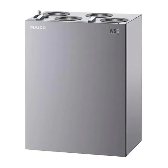
    Gerätekomponenten, Abb. A...D | DE 3 Gerätekomponenten, Abb. A...D Ausstattungsumfang abhängig von Gerätetype Pos Bezeichnung Funktion Flat Trio Außenluft Dem Lüftungsgerät zugeführte Luft      Zuluft Zuluft in die Wohnräume      III Abluft Abluft aus Wohnräumen ...
  • Seite 8 DE | Gerätekomponenten, Abb. A...D Pos Bezeichnung Funktion Flat Trio 18 Kreuz-Gegenstrom- Zur Wärmeübertragung zwischen    Wärmetauscher Abluft und Zuluft 19 Enthalpie- Zur Wärme- und Feuchteübertragung Opt. Opt. Opt.   wärmetauscher zwischen Abluft und Zuluft 20 Hauptplatine „A1“ auf Elektronik- Steuert das Lüftungsgerät ...
  • Seite 9: Zusatzplatinen (Optional)

    Zusatzplatine ZP 1 zur Ansteuerung einer der PTC-Heizregister folgenden Komponenten: Bypass ● Sole-UP (Sole-EWT geregelt/ungeregelt) ET Enthalpiewärmetauscher ● Nachheizung (elektrisch, hydraulisch etc.) Gerätetypen Artikel-Nr. ● Ansteuerung einer 3-Wege-Luftklappe eines WR 310 0095.0220 Luft-EWT WR 410 0095.0228 ● Zonenregelung WS 320 B 0095.0221  Zusatzplatine ZP 2 WS 470 B 0095.0229...
  • Seite 10: Allgemeine Hinweise

    DE | Allgemeine Hinweise Gerätetypen 5 Allgemeine Hinweise PTC-Heizregister Bypass 5.1 Qualifikation Fachinstallateur ET Enthalpiewärmetauscher Das Lüftungsgerät darf nur von einer Fach- Gerätetypen Artikel-Nr. kraft entsprechend dieser Anleitung installiert, eingerichtet, nachgerüstet, in Betrieb genom- WS 170 KBR 0095.0087   WS 170 KBL 0095.0088 men und gereinigt bzw.gewartet werden.
  • Seite 11: Bestimmungsgemäße Verwendung

    Allgemeine Hinweise | DE GEFAHR 5.2 Verwendete Warnhinweise Folgende Warnhinweise sind zusammen mit Entzündungs-/Brandgefahr durch den Sicherheitshinweisen zu beachten. Das brennbare Materialien, Flüssigkeiten oder Signalwort ist für jede Sicherheitsinformation Gase in der Nähe des Lüftungsgerätes. wie folgt ausgewählt:  In der Nähe des Lüftungsgerätes keine brennbaren Materialien, Flüssigkeiten oder GEFAHR Gase deponieren, die sich bei Hitze oder...
  • Seite 12: Sicherheitshinweise

    DE | Sicherheitshinweise 6 Sicherheitshinweise ACHTUNG: Gerätebeschädigung ● Bei Betrieb während der Bauphase Lesen und beachten Sie alle Gerätebeschädigung durch Verschmut- zung des Lüftungsgerätes und der Sicherheitsinstruktionen. Rohrleitungen.  Während der Bauphase ist ein Betrieb WARNUNG des Lüftungsgerätes unzulässig. ● Fett- und Öldämpfe von Dunstabzugs- Gefahren für Personen (auch hauben können das Gerät und die Kinder) mit eingeschränkten...
  • Seite 13 Sicherheitshinweise | DE Abmessungen (BxHxT in mm): WARNUNG 841x857x598 310/410 320/470 Verletzungsgefahr durch Her- 595x820x435 abfallendes Gerät bei falscher (LxBxH in mm) Flat Montage. 1260x582x230  Wand- und Deckenmontage LZ, QZ AL, QZ AR: Trio nur an Wänden/Decken mit 600x210x1000 ausreichender Tragkraft (Mas- QD AL, QD AR: 650x220x1100 sivwand mit min.
  • Seite 14 DE | Sicherheitshinweise zulässig und entbinden den VORSICHT Hersteller von jeglicher Gewähr- Nicht bestimmungsgemäßer leistung und Haftung. Betrieb bei falschem Einbau. Ein nicht ordnungsgemäß ein- GEFAHR gebautes Lüftungsgerät kann einen nicht bestimmungsgemä- Gesundheitsgefahr durch ßen Betrieb verursachen. fehlende Luftfilter.  Lüftungsgerät nur gemäß Bei fehlenden Luftfiltern ver- den Planungsunterlagen des schmutzt das Lüftungsgerät...
  • Seite 15 Sicherheitshinweise | DE GEFAHR VORSICHT Gefahr durch Stromschlag. Verbrennungsgefahr durch heiße Gehäuseteile bei Ge-  Vor dem Abnehmen der räten mit PTC-Heizregister Frontabdeckung und vor Elek- beim Abnehmen der Front- troinstallationen alle Versor- abdeckung. gungsstromkreise abschalten,  Nach dem Abnehmen der Netzsicherung ausschalten und Frontabdeckung nicht auf das gegen Wiedereinschalten si-...
  • Seite 16 DE | Sicherheitshinweise gasförmige Brennstoffe und des Bedienungsgriffes erkenn- der luftabsaugenden Anlage bar sein. Dies gilt als erfüllt, durch Sicherheitseinrichtungen wenn eine Absperrvorrichtung verhindert wird oder gegen Ruß (Rußabsperrer) verwendet wird. ● die Abgasabführung der raum- luftabhängigen Feuerstätte Lüftungsgeräte dürfen nicht durch besondere Sicherheitsein- installiert werden, wenn in der richtungen überwacht wird.
  • Seite 17: Anforderungen Aufstellungsort

    Anforderungen Aufstellungsort | DE Abluftfilter 310/410 7 Anforderungen Aufstellungsort 320/470 310/410 320/470 Flat Trio Flat Trio ● Umgebungstemperatur + 10 °C bis + 40 °C. ● Arbeitsraum vor dem Gerät min. 70 cm. Kondensatablauf 310/410 320/470 ● Platzbedarf für Zusatzkomponenten beachten. 1½“...
  • Seite 18: Anschlüsse

    DE | Anschlüsse 9 Anschlüsse 10 Montage Einfach-BDE [1] im Solobetrieb (= Standard- 10.1 Sicherheitshinweise einstellung), ohne Komfort-BDE (Touch- screen-BDE RLS T1 WS). Es sind bis zu ● Unfallverhütungsvorschriften 4 weitere Einfach-BDE´s parallel anschließbar beachten. Gerät generell mit  Verdrahtungspläne, Kapitel 13 bis 16. 2 Personen installieren.
  • Seite 19: Wandhalterung Anbringen

    Montage | DE Abdeckungen anbringen 4. Zum Anbringen der Frontabdeckung um- gekehrt vorgehen. Darauf achten, dass die 1. Frontabdeckung in die untere Gehäuse- Abdeckung richtig sitzt und keine Fehlluft schiene einsetzen, schließen und mit angesaugt werden kann. den 4 Schrauben (Bajonettverschluss) befestigen.
  • Seite 20: Flat-Gerät An Der Decke Oder Wand Befestigen

    DE | Montage ACHTUNG Funktionsbeeinträchtigung durch Kon- densat: Das Lüftungsgerät muss waagerecht montiert sein, damit das Kondensat einwand- frei abläuft. 1. Lüftungsgerät mit geeignetem Befesti- gungsmaterial [A], [B] oder [C] (je 4 Stück) fest mit der Decke/Wand verschrauben. Befestigungsmaterial ist bauseitig bereit- 1.
  • Seite 21: Kondensatablauf Installieren

    Montage | DE Trio 4. Dezentrale Geräte QD AR oder QD AL umbauen, je nach Einbausituation 1. Lüftungsgerät mit geeignetem Befesti- gungsmaterial an den beiden stirnseitigen Montagehaltern fest mit der Decke/Wand Pos. I: Auslieferungszustand verschrauben (4 Schrauben). Befesti- Pos. III: Umbau wie folgt gungsmaterial ist bauseitig bereitzustellen.
  • Seite 22 DE | Montage 2. Stecken Sie unten am Lüftungsgerät den mitgelieferten Kondensatbogen [B] auf den Kondensat-Ablaufstutzen [A] auf. Der Kondensatbogen besitzt eine Muffe mit Lippendichtung und ist beliebig (360°) drehbar. 3. Schließen Sie am Kondensatbogen ein 1. Frontblech und Frontabdeckung entfernen Ablaufrohr [R] (Ø...
  • Seite 23: Elektrischer Anschluss

    Elektrischer Anschluss | DE Lüftungsgerät nur mit auf dem Typen- 6. Siphon mit Tropftrichter und Sperrwas- schild angegebener Spannung und Fre- serhöhe min. 50 mm gemäß Abbildung quenz betreiben. anbringen. 7. Ablauf mit Wasser auffüllen, Dichtheit Eine feste Verdrahtung für den Netzan- und Abfluss prüfen.
  • Seite 24: De | Elektrischer Anschluss

    DE | Elektrischer Anschluss 1. Frontabdeckung(en) entfernen  Kap. 10.2. 2. Elektronikeinheit mit Hauptplatine [20] aus dem Lüftungsgerät nehmen und wie nachfolgend beschrieben einhängen. Elektronikeinschub herausnehmen und einhängen  Pfeile. Trio 1. Frontabdeckung(en) entfernen  Kap. 10.2. Die beiden Schrauben des Elektronikein- 2.
  • Seite 25: Umweltgerechte Entsorgung

    Umweltgerechte Entsorgung | DE 310/410 320/470 12 Umweltgerechte Entsorgung Flat Optionale Zusatzplatine(n) ZP 1 und/oder WARNUNG ZP 2 auf den Steckplätzen installieren Gefahr durch Stromschlag. und mit den beigefügten Anschlusskabeln Vor dem Abnehmen der Frontabdeckung anschließen. DIP-Schalter-Einstellungen das Lüftungsgerät allpolig vom Netz trennen, prüfen und ggf.
  • Seite 26: Verdrahtungsplan Hauptplatine

    BK/GR PTC- Heizregister BK/GR Bypass Fühler Bypassmotor WHBN GN YE GR T-LET T-FOL T-ZUL Lüftungsgerät WR 310/410, WS 320/470 Anschlussleitung PTC-Heizregister Elektronikeinschub Anschlussleitung Bypassmotor Steuerung KWL Geräteschalter Einfach-BDE RLS 1 WR Abluft-/Fortluftventilator B2-B5 Parallelanschluss max. 5 RLS 1 WR Außenluft-/Zuluftventilator...
  • Seite 27 Verdrahtungsplan Hauptplatine | DE Weitere Anschlussmöglichkeiten Anschlussleitung (bauseitig) für externen Sensor 1 W2‘ Anschlussleitung Touchscreen-BDE Anschlussleitung (bauseitig) für RLS T1 WS oder Modbus, z. B. externen Sensor 2 LIYY 4 x 0,34 mm² Steckplatz für optionales Kommu- Anschlussleitung (bauseitig) für nikationssteckmodul EnOcean/KNX externe Sicherheitseinrichtung 230 VAC-Anschlussklemmen zur...
  • Seite 28: Verdrahtungsplan Hauptplatine 170

    DE | Verdrahtungsplan Hauptplatine 14 Verdrahtungsplan Hauptplatine B2-B5 1 2 3 4 GNYE GNYE GNYE GNYE GNYE S-ABL PTC- Heizregister Bypass Fühler T-LET GNYE T-FOL Bypass T-ZUL Lüftungsgerät WS 170 / RB 170 Anschlussleitung PTC-Heizregister Elektronikeinschub Anschlussleitung Bypassmotor Steuerung KWL Geräteschalter Einfach-BDE RLS 1 WR / RB-ZF4 Türkontaktschalter...
  • Seite 29 Verdrahtungsplan Hauptplatine | DE Weitere Anschlussmöglichkeiten Anschlussleitung (bauseitig) für externen Sensor 2 W2‘ Anschlussleitung Touchscreen-BDE Steckplatz für optionales Kommu- RLS T1 WS oder Modbus, z. B. nikationssteckmodul EnOcean/KNX LIYY 4 x 0,34 mm² 230 VAC-Anschlussklemmen zur Anschlussleitung (bauseitig) für Beschaltung der Zusatzplatinen externe Sicherheitseinrichtung USB-Service-Schnittstelle mit potentialfreiem Kontakt 12 V/2 A...
  • Seite 30: Verdrahtungsplan Hauptplatine Flat

    DE | Verdrahtungsplan Hauptplatine Flat 15 Verdrahtungsplan Hauptplatine Anschlussleitung PTC-Heizregister Lüftungsgerät WS 160 Flat ... Anschlussleitung Bypassmotor Elektronikeinschub Geräteschalter Steuerung KWL Türkontaktschalter Einfach-BDE RLS 1 WR Abluft-/Fortluftventilator B2-B5 Parallelanschluss max. 5 Einfach-BDE´s Außenluft-/Zuluftventilator Touchscreen-BDE RLS T1 WS T-LET Temperaturfühler Lufteintritt Außenluft Anschlussleitung 230 V AC Geschirmte Steuerleitung Einfach-BDE T-FOL Temperaturfühler Fortluft...
  • Seite 31 Verdrahtungsplan Hauptplatine | DE Weitere Anschlussmöglichkeiten Anschlussleitung (bauseitig) für externen Sensor 2 W2‘ Anschlussleitung Touchscreen-BDE Steckplatz für optionales Kommu- RLS T1 WS oder Modbus, z. B. nikationssteckmodul EnOcean/KNX LIYY 4 x 0,34 mm² Steckplatz Hardware-Erweiterung Anschlussleitung (bauseitig) für Modularkabel externe Sicherheitseinrichtung 230 VAC-Anschlussklemmen zur mit potentialfreiem Kontakt 12 V/2 A Beschaltung der Zusatzplatinen...
  • Seite 32: Verdrahtungsplan Hauptplatine Trio

    DE | Verdrahtungsplan Hauptplatine Trio 16 Verdrahtungsplan Hauptplatine B2-B5 1 2 3 4 GNYE GNYE GNYE ZUL- Klappe ZUL Vent. M2.1 GNYE ABL- Klappe ABL Vent. M1.1 GNYE S-ABL Heizregister Bypass Fühler T-LET T-FOL T-ZUL Lüftungsgerät Trio Anschlussleitung Heizregister Elektronikeinschub Abluft-/Fortluftventilator Steuerung KWL Außenluft-/Zuluftventilator...
  • Seite 33 Verdrahtungsplan Hauptplatine | DE Weitere Anschlussmöglichkeiten Anschlussleitung (bauseitig) für geräteinterne und externe Sensoren W2‘ Anschlussleitung Touchscreen-BDE Anschlussleitung (bauseitig) für RLS T1 WS oder Modbus, z. B. geräteinterne und externe Sensoren LIYY 4 x 0,34 mm² Steckplatz für optionales Kommuni Anschlussleitung (bauseitig) für kationssteckmodul EnOcean/KNX externe Sicherheitseinrichtung 230 VAC-Anschlussklemmen zur...
  • Seite 34: Verdrahtungsplan Externe Sensoren

    DE | Verdrahtungsplan externe Sensoren – Platine A2 17 Verdrahtungsplan externe Sensoren – Platine A2 – Lüftungsgerät Die Sensoreingänge der Steuerung sind frei Elektronikeinschub parametrierbar. Die Eingänge sind nicht auf eine Steuerung KWL bestimmte Sensorart festgelegt. -Sensor ( Zubehör) Bei Inbetriebnahme eines Sensors muss der Luftqualitätsregler (...
  • Seite 35: Verdrahtungsplan Modbus

    Verdrahtungsplan ModBus – Platine A2 | DE 18 Verdrahtungsplan ModBus – Platine A2 – Bei im Parametermenü deaktiviertem Kom- Lüftungsgerät fort-BDE (Touchscreen-BDE RLS T1 WS) Elektronikeinschub können die Anschlussklemmen am Klem- Steuerung KWL menblock RS 485 als ModBus-Schnittstelle W11 Anschlussleitung ModBus (bauseitig), genutzt werden.
  • Seite 36: Verdrahtungsplan Glt

    DE | Verdrahtungsplan GLT – Platine A2 19 Verdrahtungsplan GLT – Platine A2 – 12VDC - Betriebsanzeige 12VDC - Filterwechselanzeige 12VDC - Störmeldung Luftstufe Aus* * Bei Einstellung "Lüftungsstufe Aus gesperrt" läuft das Gerät in Lüftungsstufe Feuchteschutz Lüftungsgerät Elektronikeinschub Steuerung KWL Durch Änderung der Einstellung „Einfach-BDE“...
  • Seite 37: Scope Of Delivery

    17 Wiring diagram for external sensors ..62 tively you can download the instructions from 18 Wiring diagram for ModBus ....63 the download area at www.maico-ventilato- ren.com. 19 Wiring diagram for building control tec. 64 Annexe: Product fiches RVU´s ....99...
  • Seite 38: Unit Components

    UK | Unit components, Fig. A...D 3 Unit components, Fig. A...D Scope of equipment depends on unit type Item Designation Function Flat Trio Outside air Air supplied to the ventilation unit      Supply air Supply air into the living areas ...
  • Seite 39 Unit components, Fig. A...D | UK Item Designation Function Flat Trio 18 Cross counterflow For transferring heat between exhaust air    heat exchanger and supply air 19 Enthalpy heat For transferring heat and Opt. Opt. Opt.   exchanger humidity between exhaust air and supply air 20 Main board „A1“...
  • Seite 40: Unit Types

    ● Brine circulation pump (brine EHE regu- ET Enthalpy heat exchanger lated/unregulated) Unit types Article no. ● Supplementary heating (electrical, hydraulic etc.) WR 310 0095.0220 WR 410 0095.0228 ● Control of a 3-way air flap of an air EHE WS 320 B 0095.0221 ●...
  • Seite 41: General Notes

    General notes | UK ** Connection sockets of external and Unit types outgoing air can be fitted lengthwise PTC heat register on the unit base Bypass ET Enthalpy heat exchanger 5 General notes Unit types Article no. WS 170 KBR 0095.0087 ...
  • Seite 42: Warnings Used

    UK | General notes DANGER 5.2 Warnings used The following warnings should be observed Risk of combustion/fire from flam- along with the safety instructions. The signal mable materials, liquids or gases in the word for safety information is selected as vicinity of the ventilation unit.
  • Seite 43: Safety Instructions

    Safety instructions | UK 6 Safety instructions NOTICE: Damage to the unit ● If operated during the build phase, Read and observe all the damage to unit caused by contamina- tion of the ventilation unit and piping. safety instructions.  Ventilation unit operation is not permit- ted during the build phase.
  • Seite 44 UK | Safety instructions Dimensions (WxHxD in mm): WARNING 841x857x598 310/410 320/470 Risk of injury from falling unit 595x820x435 if installed incorrectly. (LxWxH in mm) Flat  Only install on walls or 1260x582x230 ceilings with sufficient load- Trio LZ, QZ AL, QZ AR: bearing capacity (solid wall with 600x210x1000 at least 200 kg/m³) and with...
  • Seite 45 Safety instructions | UK  Other changes and modifica- CAUTION tions to the unit are not permit- Intended operation not en- ted and release the manufac- sured if installed incorrectly. turer from all guarantees and A ventilation unit not installed liability.
  • Seite 46 UK | Safety instructions DANGER CAUTION Danger from Danger of burning from hot housing parts on units with electric shock. PTC heat register when re-  Before removing the front moving the front cover. cover and installing the elec-  After removing the front trics, switch off all supply cir- cover, do not touch the heat cuits and secure them against...
  • Seite 47 Safety instructions | UK Ventilation systems must not ● the extraction of exhaust gas from the air-ventilated fire- be installed if there are air-ven- places is monitored by special tilated fireplaces in the living unit safety equipment. In the case that are connected to exhaust of air-ventilated fireplaces for gas systems, which themselves...
  • Seite 48: Requirements Of The Installation Site

    UK | Requirements of the installation site 7 Requirements of the installation site 8 Technical data 310/410 320/470 Dimensions (WxHxD) 310/410 320/470 Flat Trio 841 x 857 x 598 mm ● Ambient temperature + 10 °C to + 40 °C. ●...
  • Seite 49: Connections

    Connections | UK Power consumption 310/410 9 Connections (unit) at 100 Pa counter 34 ... 220 W Simple control unit [1] in solo mode (= pressure per duct 320/470 K/B/KB: standard setting), without comfort control unit 34 ... 220 W (touchscreen control unit RLS T1 WS).
  • Seite 50: Installation

    UK | Installation Fitting covers 10 Installation 1. Place front cover in the bottom housing rail, close and secure with 4 screws 10.1 Safety instructions (bayonet closure). 2. Fit front plate in the two lugs [L] and ● Observe accident prevention close (magnets [M]).
  • Seite 51 Installation | UK Trio NOTICE Removing/fitting front cover Function will be impaired by condensate: The ventilation unit must be installed hori- WARNING  Chapter 10.1 zontally so that the condensate can drain off unhindered. 1. Install rail [S2] on wall with appropriate mounting material.
  • Seite 52 UK | Installation 1. Firmly screw down ventilation unit to cei- 1. Firmly screw down ventilation unit to ling/wall with appropriate mounting mate- ceiling/wall with appropriate mounting ma- rial [A], [B] or [C] (4 items each). Mounting terial on mounting supports at both face material is to be supplied by the customer.
  • Seite 53 Installation | UK Trio 4. Modify decentralised units AR or QD AL, depending on installation situation. 1. Remove front plate and front cover  chapter 10.2. 2. Fit a siphon and open drip funnel on the condensate drain. 3. If the humidity level in the installation room Pos.
  • Seite 54: Electrical Connection

    UK | Electrical connection 2. Attach the condensate elbow [B] supplied 7. Fill drain with water, check seal integrity to the condensate discharge outlet [A] on and drainage. Fill the siphon up with water the bottom of the ventilation unit. The con- after long dry periods too.
  • Seite 55 Electrical connection | UK The ventilation unit may only be operated using the voltage and frequency shown on the rating plate. 1. Remove front cover(s)  chap. 10.2. Fixed wiring is prescribed for the mains 2. Take electronic unit with main printed connection.
  • Seite 56 UK | Electrical connection 310/410 320/470 Flat Install optional additional circuit board(s) ZP 1 and/or ZP 2 in slots and connect with connecting cables provided. Check DIP switch settings and adjust if necessary. For electrical connection and DIP switch settings  installation instructions for respective accessories.
  • Seite 57: Environmentally Responsible Disposal

    Environmentally responsible disposal | UK Professional disposal avoids detrimen- 12 Environmentally responsible tal impact on people and the environ- disposal ment and allows valuable materials to be reused. WARNING Once they are no longer needed, air filters, Danger from electric shock. packaging materials and used units should Before removing the front cover, disconnect be disposed of in compliance with local...
  • Seite 58: Wiring Diagram For Main Board

    Fühler Bypassmotor WHBN GN YE GR T-LET T-FOL T-ZUL Ventilation unit WR 310/410, WS 320/470 Connecting cable for PTC heat register Electronic slide-in module Connecting cable for bypass motor CDV unit control Unit switch Simple control unit RLS 1 WR Exhaust air/outgoing air fan B2-B5 Parallel connection max.
  • Seite 59 Wiring diagram for main board | UK Further connection options Connecting cable (provided by customer) for external sensor 1 W2’ Connecting cable for touchscreen Connecting cable (provided by control unit RLS T1 WS or Modbus, customer) for external sensor 2 e.g.
  • Seite 60: Wiring Diagram For Main Board 170

    UK | Wiring diagram for main board 14 Wiring diagram for main board B2-B5 1 2 3 4 GNYE GNYE GNYE GNYE GNYE S-ABL PTC- Heizregister Bypass Fühler T-LET GNYE T-FOL Bypass T-ZUL Connecting cable for PTC heat register Ventilation unit WS 170 / RB 170 Connecting cable for bypass motor Electronic slide-in module CDV unit control...
  • Seite 61 Wiring diagram for main board | UK Further connection options Connecting cable (provided by customer) for external sensor 2 W2’ Connecting cable for touchscreen Slot for optional communication control unit RLS T1 WS or Modbus, plug-in module EnOcean/KNX e.g. LIYY 4 x 0.34 mm² 230 VAC connecting terminals for Connecting cable (provided by custo- switching the additional boards...
  • Seite 62: Wiring Diagram For Main Board Flat

    UK | Wiring diagram for main board Flat 15 Wiring diagram for main board Ventilation unit WS 160 Flat ... Connecting cable for PTC heat register Electronic slide-in module Connecting cable for bypass motor CDV unit control Unit switch Simple control unit RLS 1 WR Door contact switch B2-B5 Parallel connection max.
  • Seite 63 Wiring diagram for main board | UK Further connection options Connecting cable (provided by customer) for external sensor 2 W2’ Connecting cable for touchscreen Slot for optional communication control unit RLS T1 WS or Modbus, plug-in module EnOcean/KNX e.g. LIYY 4 x 0.34 mm² Slot for modular cable hardware Connecting cable (provided by custo- extension...
  • Seite 64: Wiring Diagram For Main Board Trio

    UK | Wiring diagram for main board Trio 16 Wiring diagram for main board B2-B5 1 2 3 4 GNYE GNYE GNYE ZUL- Klappe ZUL Vent. M2.1 GNYE ABL- Klappe ABL Vent. M1.1 GNYE S-ABL Heizregister Bypass Fühler T-LET T-FOL T-ZUL Ventilation unit Trio Connecting cable heat register...
  • Seite 65 Wiring diagram for main board | UK Further connection options Connection cable (provided by custo- mer) for internal and external sensors W2’ Connecting cable for touchscreen Connection cable (provided by custo- control unit RLS T1 WS or Modbus, mer) for internal and external sensors e.g.
  • Seite 66: Wiring Diagram For External Sensors

    UK | Wiring diagram for external sensors – circuit board A2 r.h. 17 Wiring diagram for external sensors – circuit board A2 – r.h. Ventilation unit The control’s sensor inputs can be freely Electronic slide-in module parametrised. The inputs are not defined for a CDV unit control particular sensor type.
  • Seite 67: Wiring Diagram For Modbus

    Wiring diagram for ModBus – circuit board A2 r.h. | UK 18 Wiring diagram for ModBus – circuit board A2 – If the comfort control unit is deactivated in the Ventilation unit parameter menu (touchscreen control unit Electronic slide-in module RLS T1 WS), the connection terminals on the CDV unit control RS 485 terminal block can be used as the...
  • Seite 68: Wiring Diagram For Building Control Tec

    UK | Wiring diagram for building control technology – circuit board A2 r.h. 19 Wiring diagram for building control technology – circuit board A2 – 12VDC - Operating display 12VDC - Filter change display 12VDC - Fault message Ventilation level Reduced ventilation Nominal ventilation Intensive ventilation...
  • Seite 69: Volume De Fourniture

    Flat Appareil de ventilation, unité de com- mande simple (RLS 1 WR), kit d‘aide au monta- Mentions légales : © Maico Elektroapparate- ge (équerre, 4 vis, douille, écrou papillon), intro- Fabrik GmbH. Traduction de la notice allemande duction rapide et la présente notice d‘installation.
  • Seite 70: Composants D'appareil

    FR | Composants d’appareil, Fig. A...D r.h. 3 Composants d’appareil, Fig. A...D Étendue de l’équipement en fonction du type d’appareil Pos Bezeichnung Funktion Flat Trio Air extérieur Air amené à l‘appareil de ventilation      Air entrant Air entrant dans les pièces d‘habitation ...
  • Seite 71 Composants d’appareil, Fig. A...D r.h. | FR Pos Bezeichnung Funktion Flat Trio 17 Ventilateur d’air Achemine l’air frais dans les pièces      extérieur/air entrant Échangeur de chaleur Pour le transfert de la chaleur entre l’air sortant à...
  • Seite 72: Types D'appareils

    ET Échangeur de chaleur enthalpique saumure régulé/non régulé) Types Référence ● Réchauffage (électrique, hydraulique etc.) d'appareils ● Commande d’un clapet d’air 3 voies d’un WR 310 0095.0220 EG à air WR 410 0095.0228 ● Régulation par zone WS 320 B 0095.0221...
  • Seite 73: Remarques Générales

    Remarques générales r.h. | FR vent être montées en 3 positions (sur la Types d’appareils face avant, le côté longitudinal ou à travers Registre de chauffage PTC le fond de l‘appareil). Bypass ** Les pièces de raccordement pour l‘air ET Échangeur de chaleur enthalpique extérieur et l‘air rejeté...
  • Seite 74: Avertissements Utilisés

    FR | Remarques générales r.h. 5.2 Avertissements utilisés 5.4 Utilisation non conforme Les avertissement suivants sont à observer En utilisant l’appareil de ventilation, observez conjointement aux consignes de sécurité. Les toujours les informations de sécurité fonda- termes de signalisation correspondant aux mentales.
  • Seite 75 Remarques générales r.h. | FR AVERTISSEMENT ● l’assèchement des constructions neuves). L’appareil de ventilation n’est pas équipé Danger pour la santé par produits d’écoulement de condensat et est endom- chimiques ou gaz/vapeurs agressifs. magé par une accumulation excessive de Les produits chimiques ou gaz/vapeurs condensat qui ne peut pas être évacué.
  • Seite 76: Consignes De Sécurité

    FR | Consignes de sécurité r.h. 6 Consignes de sécurité DANGER Danger au cours du trans- Lisez et observez toutes les port dû à des charges trop instructions de sécurité. lourdes ou à des chutes de charges. AVERTISSEMENT  Respecter les consignes de Danger pour les personnes sécurité...
  • Seite 77 Consignes de sécurité r.h. | FR AVERTISSEMENT DANGER Danger présenté par l'exploi- Dangers en cas de montage tation d'appareils de venti- ultérieur d'éléments rappor- lation dont le montage n'est tés ou de transformations pas terminé (appareil ouvert/ influant sur le système de sans raccords tubulaires).
  • Seite 78 FR | Consignes de sécurité r.h.  Tenir compte de l’encom- PRUDENCE brement pour les composants Utilisation non conforme supplémentaires (silencieux suite à montage erroné. tubulaires, réchauffage, etc.). Si l'appareil de ventilation  Toute autre modification et n'est pas monté correctement, transformation apportée sur son exploitation peut être non l’appareil sont rigoureusement...
  • Seite 79 Consignes de sécurité r.h. | FR  Prévoir un dispositif de cou- PRUDENCE pure du secteur avec une ou- Danger pour la santé pré- verture de contact d’au moins senté par un appareil de 3 mm par pôle. ventilation qui n'est pas nettoyé/entretenu correcte- ment.
  • Seite 80 FR | Consignes de sécurité r.h. ● que la conduite de gaz DANGER d’échappement des foyers Danger de mort en cas d’utili- dépendants de l’air ambiant sation avec des foyers dépen- est contrôlée par des disposi- dants de l’air ambiant. tifs de sécurité...
  • Seite 81 Consignes de sécurité r.h. | FR Mesures de protection contre En cas de présence de foyers à combustibles solides, le dis- les incendies positif d’arrêt ne doit pouvoir se En matière de protection contre commander que manuellement. les incendies des installations La position du dispositif d’arrêt de ventilation, les règlements doit être visible sur le réglage...
  • Seite 82: Exigences Sur Le Lieu D'installation

    FR | Exigences sur le lieu d’installation r.h. 7 Exigences sur le lieu d’installation 8 Caractéristiques techniques 310/410 320/470 Dimensions (LxHxP) 310/410 320/470 Flat Trio 841 x 857 x 598 mm ● Température ambiante de + 10 °C à + 40 °C. 595 x 820 x 435 mm ●...
  • Seite 83: Raccords

    KNX K-SM (en option) cher jusqu’à 4 autres unités de commandes Pour des composants recommandés  simples en parallèle  Plan de câblage, Catalogue MAICO ou www.maico-ventila- chapitre 13 à 18. toren.com. Commande à écran tactile RLS T1 WS (en option) combinable avec jusqu’à...
  • Seite 84: Montage

    FR | Montage r.h. 10 Montage 10.2 Retirer/placer les caches de protection 10.1 Consignes de sécurité 310/410 320/470 ● Respecter les consignes de Retirer les caches de protection 1. Basculer la tôle de devant sur les deux prévention d‘accident. Prévoir angles supérieurs (aimants [M]) et retirer en principe 2 personnes pour par le haut.
  • Seite 85 Montage r.h. | FR 3. Pour remettre en place le cache de protec- Flat tion, reprendre les opérations dans le sens Déposer / poser le cache de protection inverse. Veiller à la bonne assise du cache pour éviter toute aspiration d‘air d‘appoint. AVERTISSEMENT ...
  • Seite 86 FR | Montage r.h. A Tiges filetées 1. Fixer les tiges filetées au plafond. 2. Accrocher l‘appareil de ventilation et le sécuriser contre la chute. B Équerre de fixation au plafond avec 310/410 320/470 : Coller les deux tam- élément amortisseur pons en caoutchouc [G] servant d’écar- 1.
  • Seite 87 Montage r.h. | FR montage situés à la face avant. Le matéri- Positions de montage possibles : sur le el de fixation sera fourni par le client. Tenir côté longitudinal [I] ou à travers le fond de compte du poids de 50 kg. l‘appareil [III].
  • Seite 88 FR | Montage r.h. 1. Enlever la tôle de devant et le cache de protection avant  Chapitre 10.2. Figure : Appareil de ventilation en version 2. Placer un siphon et un entonnoir à gouttes droite, version gauche inversée ouvert sur l’écoulement de condensat. 3.
  • Seite 89: Branchement Électrique

    Branchement électrique r.h. | FR 5. En cas d‘humidité exagérément élevée 11 Branchement électrique dans le local d‘installation, isoler l‘écou- lement et l‘embout de l‘écoulement de AVERTISSEMENT condensat pour éviter le condensat. Risque d'électrocution. ATTENTION Avant de déposer le cache de protection avant, couper du secteur l'appareil sur tous Possibilité...
  • Seite 90 FR | Branchement électrique r.h. 310/410 320/470 1. Retirer le(s) cache(s) de protection  Chap. 10.2. 2. Sortir l‘unité électronique avec la platine principale [20] de l‘appareil de ventilation et l‘accrocher. Pour ce faire, soulever le module électro- nique enfichable et le retirer du comparti- ment électronique.
  • Seite 91: Élimination Respect. De L'environnement

    Élimination respectueuse de l’environnement r.h. | FR de câblage des chapitres 13 à 18. Pour Trio les variantes de branchement des com- 1. Retirer le(s) cache(s) de protection posants supplémentaires  Notice de  Chap. 10.2. montage de l’accessoire. 2. Sortir l‘unité électronique avec la platine 310/410 320/470 principale [20] de l‘appareil de ventilation...
  • Seite 92: Plan De Câblage, Carte-Principale

    Bypass Fühler Bypassmotor WHBN GN YE GR T-LET T-FOL T-ZUL Appareil de ventilation WR 310/410, W2´ Câble de commande blindé pour WS 320/470 RLS T1 WS (à fournir par le client), p. ex. LIYY 4 x 0,34 mm² Module électronique...
  • Seite 93 Plan de câblage, carte-principale r.h. | FR T-LET Sonde de température entrée d’air Câble de raccordement (à fournir par Airextérieur le client) pour le contact multifonction- T-FOL Sonde de température de l’air rejeté nel (contact relais libre de potentiel T-FOL Sonde de température de l’air entrant 230 VAC/5A ou 30 VDC/5A) S-ABL Détecteur combiné...
  • Seite 94: Plan De Câblage, Carte-Principale 170

    FR | Plan de câblage, carte-principale r.h. 14 Plan de câblage, carte-principale B2-B5 1 2 3 4 GNYE GNYE GNYE GNYE GNYE S-ABL PTC- Heizregister Bypass Fühler T-LET GNYE T-FOL Bypass T-ZUL Appareil de ventilation WS 170/RB 170 W2´ Câble de commande blindé pour Module électronique RLS T1 WS (à...
  • Seite 95 Plan de câblage, carte-principale r.h. | FR T-LET Sonde de température entrée d’air Câble de raccordement (à fournir par Airextérieur le client) pour détecteur 1 externe T-FOL Sonde de température de l’air rejeté Câble de raccordement (à fournir par T-FOL Sonde de température de l’air entrant le client) pour détecteur 2 externe S-ABL Détecteur combiné...
  • Seite 96: Plan De Câblage, Carte-Principale Flat

    FR | Plan de câblage, carte-principale r.h. Flat 15 Plan de câblage, carte-principale W2´ Câble de commande blindé pour Appareil de ventilation WS 160 Flat ... RLS T1 WS (à fournir par le client), Module électronique p. ex. LIYY 4 x 0,34 mm² Commande appareil VMC double flux Unité...
  • Seite 97 Plan de câblage, carte-principale r.h. | FR T-LET Sonde de température entrée d’air Câble de raccordement (à fournir par Airextérieur le client) pour détecteur 1 externe T-FOL Sonde de température de l’air rejeté Câble de raccordement (à fournir par T-FOL Sonde de température de l’air entrant le client) pour détecteur 2 externe S-ABL Détecteur combiné...
  • Seite 98: Plan De Câblage, Carte-Principale Trio

    FR | Plan de câblage, carte-principale r.h. Trio 16 Plan de câblage, carte-principale B2-B5 1 2 3 4 GNYE GNYE GNYE ZUL- Klappe ZUL Vent. M2.1 GNYE ABL- Klappe ABL Vent. M1.1 GNYE S-ABL Heizregister Bypass Fühler T-LET T-FOL T-ZUL W2´...
  • Seite 99 Plan de câblage, carte-principale r.h. | FR T-LET Sonde de température entrée d’air Câble de raccordement (à fournir par Airextérieur le client) pour le contact multifonction- T-FOL Sonde de température de l’air rejeté nel (contact relais libre de potentiel T-FOL Sonde de température de l’air entrant 230 VAC/5A ou 30 VDC/5A) S-ABL Détecteur combiné...
  • Seite 100: Plan De Câblage Des Détecteurs Externes

    FR | Plan de câblage des détecteurs externes – carte A2 COV 17 Plan de câblage des détecteurs externes – carte A2 – h.r. Appareil de ventilation Les entrées des détecteurs de la commande Module électronique sont librement paramétrables. Les entrées Commande appareil VMC double flux ne sont pas fixées sur un certain type de Détecteur de CO...
  • Seite 101: Plan De Câblage Modbus

    Plan de câblage ModBus – carte A2 COV | FR 18 Plan de câblage ModBus – carte A2 – Lorsque l’unité de commande Confort Appareil de ventilation (commande à écran tactile RLS T1 WS) est Module électronique désactivée dans le menu de paramétrage, Commande appareil VMC double flux les bornes de raccordement sur le bornier W11 Câble de raccordement ModBus...
  • Seite 102: Plan De Câblage Domotique

    FR | Plan de câblage domotique – carte A2 COV 19 Plan de câblage domotique – carte A2 – 12VDC - A chage de fonctionnement 12VDC - A chage de remplacement de ltres 12VDC - Message d'erreur Niveau de ventilation Arrêt* Arrêt Arrêt...
  • Seite 103: Anhang: Produktdatenblätter Rvu´s

    Produktdatenblatt RVU Product fiche RVU a) Lieferant Maico Elektroapparate-Fabrik GmbH supplier´s name WR 310 (0095.0220) b) Modellkennung (Code) WS 320 B (0095.0221) supplier model (code) WS 320 K (0095.0222) WS 320 KB (0095.0223) c) Spezifischer Energieverbrauch cold average warm kWh/(m²∙a) specific energy consumption -82.16...
  • Seite 104 Produktdatenblatt RVU Product fiche RVU a) Lieferant Maico Elektroapparate-Fabrik GmbH supplier´s name WS 320 ET (0095.0224) b) Modellkennung (Code) WS 320 BET (0095.0225) supplier model (code) WS 320 KET (0095.0226) WS 320 KBET (0095.0227) c) Spezifischer Energieverbrauch cold average warm kWh/(m²∙a)
  • Seite 105 Produktdatenblatt RVU Product fiche RVU a) Lieferant Maico Elektroapparate-Fabrik GmbH supplier´s name WR 410 (0095.0228) b) Modellkennung (Code) WS 470 B (0095.0229) supplier model (code) WS 470 K (0095.0230) WS 470 KB (0095.0231) c) Spezifischer Energieverbrauch cold average warm kWh/(m²∙a) specific energy consumption -78.9...
  • Seite 106 Produktdatenblatt RVU Product fiche RVU a) Lieferant Maico Elektroapparate-Fabrik GmbH supplier´s name b) Modellkennung (Code) WS 470 ET (0095.0232) WS 470 BET (0095.0233) supplier model (code) WS 470 KET (0095.0234) WS 470 KBET (0095.0235) c) Spezifischer Energieverbrauch cold average warm kWh/(m²∙a)
  • Seite 107 Produktdatenblatt RVU Product fiche RVU a) Lieferant Maico Elektroapparate-Fabrik GmbH supplier´s name AEREX HaustechnikSysteme GmbH WS 170 KBR (0095.0087) b) Modellkennung (Code) supplier model (code) WS 170 KBL (0095.0088) RB 170 CBR (0040.0085) RB 170 CBL (0040.0086) c) Spezifischer Energieverbrauch...
  • Seite 108 Produktdatenblatt RVU Product fiche RVU a) Lieferant Maico Elektroapparate-Fabrik GmbH supplier´s name b) Modellkennung (Code) WS 170 KBRET (0095.0114) supplier model (code) WS 170 KBLET (0095.0115) c) Spezifischer Energieverbrauch cold average warm kWh/(m²∙a) specific energy consumption -72.58 -36.53 -13.25 d) Typ...
  • Seite 109 Produktdatenblatt RVU Product fiche RVU a) Lieferant Maico Elektroapparate-Fabrik GmbH supplier´s name WS 160 Flat ET (0095.0090) b) Modellkennung (Code) WS 160 Flat KET (0095.0091) supplier model (code) WS 160 Flat BET (0095.0092) WS 160 Flat KBET (0095.0093) WS 160 Flat KBZET (0095.0094)
  • Seite 110 Anweisungen für Anbringung regelbarer AUL-, FOL-Gitter – instructions to install regulated supply/exhaust grilles s) Internetadresse www.maico-ventilatoren.com internet address t) Druckschwankungsempfindlichkeit Luftstrom – airflow sensitivity to pressure variations at -20 Pa / +20 Pa u) Luftdichtheit zwischen innen und außen...
  • Seite 111 Anweisungen für Anbringung regelbarer AUL-, FOL-Gitter – instructions to install regulated supply/exhaust grilles s) Internetadresse www.maico-ventilatoren.com internet address t) Druckschwankungsempfindlichkeit Luftstrom – airflow sensitivity to pressure variations at -20 Pa / +20 Pa u) Luftdichtheit zwischen innen und außen...
  • Seite 112 MAICO Elektroapparate-Fabrik GmbH Steinbeisstr. 20 78056 Villingen-Schwenningen ● ● ● Germany Service +49 7720 6940 technik@maico.de ● ●...

Inhaltsverzeichnis