
Verwandte Anleitungen für Maico aeronom WS 150


Inhaltszusammenfassung für Maico aeronom WS 150
- Seite 1 Wärmerückgewinnungs- system WS 150 Einbau-, Bedienungs- und Wartungsanleitung www. m aic o-v ent ilat oren.c om...
-
Seite 2: Wichtige Hinweise Zur Anleitung
Wichtige Hinweise zur Anleitung Wichtige Hinweise zur Anleitung Lesen Sie diese Anleitung auf jeden Fall sorgfältig und vollständig durch, bevor Sie das Lüftungsgerät bedienen, , , , , einbauen oder anschließen. Bewahren Sie die Anleitung gut auf ! Hinweise, Bedienung: Die ersten Kapitel richten sich an den Benutzer. Hier sind wichtige unbedingt lesen ! Informationen über das Lüftungssystem sowie Einstellmöglichkeiten an der Bedieneinheit aufgeführt. -
Seite 3: Inhaltsverzeichnis
Inhaltsverzeichnis Inhaltsverzeichnis Seite Einführung ................ Lieferumfang ..............Symbole in dieser Anleitung ..........Einsatzgebiete, Verwendungszweck ........ Bestimmungen für den Betrieb mit Feuerstätten ....Sicherheitshinweise ............Das Lüftungssystem ............Übersicht ................Funktion ................Systemmerkmale ............. Systemerweiterungen ............Systemzubehör ..............Sicherheitseinrichtungen ..........Bedienung ................ Lüftungsgerät .............. -
Seite 4: Einführung
1. Einführung 1.1 Lieferumfang 1. Einführung 1.1 Lieferumfang Lüftungsgerät Diese Bedienungs-, Wartungs- und Montageanleitung Die Bedieneinheit ist nicht im Lieferumfang enthalten 1.2 Symbole in dieser Anleitung Warnsymbol: Hier ist äußerste Vorsicht und Umsicht geboten. Bei Fehlver- halten besteht direkte Verletzungsgefahr für den Systembediener oder Dritte. Bei Nichtbeachtung kann das Lüftungssystem Schaden nehmen. -
Seite 5: Sicherheitshinweise
1. Einführung 1.5 Sicherheitshinweise 1.5 Sicherheitshinweise 1. Setzen Sie das Lüftungsgerät nur gemäß dem zuvor beschriebenen Verwendungszweck ein. 2. Lassen Sie sich nach der Installation durch Ihren Installateur an Gerät und WARNUNG Bedieneinheit einweisen. 3. Betreiben Sie das Lüftungsgerät niemals ohne Filter. 4. -
Seite 6: Das Lüftungssystem
2. Das Lüftungssystem... -
Seite 7: Übersicht
2. Das Lüftungssystem 2.1 Übersicht 17. Integrieren Sie auf keinen Fall Dunstabzugshauben in den Abluft- oder Fortluftkreislauf des Lüftungsgerätes. Diese sind separat zu betreiben. 18. Betrieb mit raumluftabhängigen Feuerstätten: Für Wohnungen mit Lüf- WARNUNG tungsanlagen unterliegen diese der DIN 1946, Teil 6. Beachten Sie unbedingt die Brandschutzanforderungen. -
Seite 8: Systemmerkmale
2. Das Lüftungssystem 2.3 Systemmerkmale 2.3 Systemmerkmale Bedienung des Lüftungsgerätes mit Bedieneinheit (2). Die hier gezeigte Bedieneinheit besitzt eine Zeitschaltuhr für den Automatikbetrieb zwi- schen Lüfterstufe 1 und 2 sowie eine Filterwechselanzeige. Wärmebereitstellungsgrad bis zu 90%. Zuluft- und Abluftventilator mit besonders energiesparendem Gleichstrom- motor. -
Seite 9: Systemzubehör
2. Das Lüftungssystem 2.5 Systemzubehör 2.5 Systemzubehör Bedieneinheit Ersatzfilter-Set Schalldämpfer Elektro-Lufterhitzer mit Eigensteuerung Luft-Wasser Heizregister (zur Luftnacherhitzung) Elektronischer Temperaturregler 2.6 Sicherheitseinrichtungen Das Lüftungsgerät ist mit einem Sicherheitsschalter ausgestattet. Dieser spricht bei heruntergeklappter Fronttür an. Das Lüftungsgerät schaltet automatisch ab. VORSICHT Der Sicherheitsschalter darf nicht außer Funktion gesetzt werden ! Es besteht Verletzungsgefahr durch sich drehende Ventilatoren. -
Seite 10: Lüftungsgerät - Übersicht
2. Das Lüftungssystem 2.8 Lüftungsgerät – Übersicht... -
Seite 11: Lüftungsgerät
2. Das Lüftungssystem 2.8 Lüftungsgerät 2.8 Lüftungsgerät R = Lüftungsgerät in Rechtsausführung L = Lüftungsgerät in Linksausführung A = Außenluft: Die aus dem Freien angesaugte Frischluft. B = Zuluft: Die in die Wohnung zuströmende, erwärmte Frischluft. C = Abluft: Die aus der Wohnung abgesaugte, verbrauchte warme Luft. D = Fortluft: Die ins Freie abgeführte verbrauchte und abgekühlte Luft. -
Seite 12: Reinigung, Wartung
3. Reinigung, Wartung 3.1 Sicherheitshinweise 3. Reinigung, Wartung 3.1 Sicherheitshinweise Trennen Sie zu Reinigungs- und Wartungsarbeiten das Lüftungsgerät sowie alle Zusatzkomponeten vom Netz (Netzsicherung ausschalten). Verletzungsgefahr durch herunterklappende Fronttür: Halten Sie GEFAHR die Fronttür beim Öffnen der Schnellspannverschlüsse immer mit einer Hand fest, damit diese nicht plötzlich herunterklappt. -
Seite 13: Lüftungsgerät Reinigen
3. Reinigung, Wartung 3.3 Lüftungsgerät reinigen 3.3 Lüftungsgerät reinigen Abhängig vom Verschmutzungsgrad empfehlen wir eine: jährliche Innenreinigung jährliche Reinigung des Wärmetauschers halbjährliche Reinigung des Kondensatabflusses und Siphons Wärmetauscher (siehe Kapitel 2.8, Pos. 7) reinigen, Innenreinigung des Lüftungsgerätes 1. Netzsicherung ausschalten. 2. -
Seite 14: Montage Des Lüftungsgerätes
4. Montage des Lüftungsgerätes (Fachinstallateur) 4.1 Vor der Installation 4. Montage des Lüftungsgerätes 4.1 Vor der Installation / Aufstellungsplan Transport Beachten Sie beim Transport, dass das Gerät weder beschädigt noch umgeworfen wird. Beachten Sie die gültigen Sicherheits- und Unfallverhütungsvorschriften. VORSICHT Für Schäden durch unsachgemäßen Transport und unsachgemäße Lagerung übernimmt der Hersteller keine Gewährleistung und Haftung. -
Seite 15: Lüftungsgerät Aufstellen
4. Montage des Lüftungsgerätes (Fachinstallateur) 4.2 Lüftungsgerät aufstellen 4.2 Lüftungsgerät aufstellen 1. Stellen Sie das Lüftungsgerät am Montageort ab und richten sie das Gerät waagrecht aus. 2. Berücksichtigen Sie für Einbau und Betrieb einen ausreichenden Freiraum vor dem Gerät: Die Fronttür muss sich heruntergeklappen, die Filter und der Wärmetauscher ausbauen lassen. -
Seite 16: Elektrischen Anschluss Vornehmen
4. Montage des Lüftungsgerätes (Fachinstallateur) 4.5 Elektrischen Anschluss vornehmen 4.5 Elektrischen Anschluss vornehmen Der elektrische Anschluss des Lüftungsgerätes und der Zusatzkomponenten darf nur von Elektrofachkräften vorgenommen werden. Betreiben Sie das Lüftungsgerät nur mit der auf dem Typenschild GEFAHR angegebenen Bemessungsspannung. Schließen Sie das Lüftungsgerät an einer festverlegten elektrischen Installation an. -
Seite 17: Verdrahtungsplan: Beispielanschluss Mit Bedieneinheit
4. Montage des Lüftungsgerätes (Fachinstallateur) 4.6 Verdrahtungsplan 4.6 Verdrahtungsplan: Beispielanschluss mit Bedieneinheit Hinweis: Die hier gezeigte optionale Bedieneinheit ist eine 3-Stufen- steuerung mit Zeitschaltuhr und Filterwechselanzeige. Für den Anschluss an das Lüftungsgerät gilt der oben dargestellte Ver- drahtungsplan. Für Informationen zur Bedieneinheit siehe zugehörige Anleitung. -
Seite 18: Einstellungen Am Schaltnetzteil
4. Montage des Lüftungsgerätes (Fachinstallateur) 4.7 Einstellungen am Schaltnetzteil 4.7 Einstellungen am Schaltnetzteil DIP-Schalter-Einstellungen Das Lüftungsgerät ist mit einer elektronischen Volumenstromregelung für konstanten Luftstrom ausgestattet. Die Geräteelektronik passt die Drehzahl beider Ventilatoren an, um die eingestellte Luftmenge unabhängig vom Systemdruck konstant zu halten. Aus diesem Grund drehen sich die beiden Ventilatoren nicht immer mit der gleichen Drehzahl. - Seite 19 4. Montage des Lüftungsgerätes (Fachinstallateur) 4.7 Einstellungen am Schaltnetzteil DIP-Schalter 3 + 4 für Lüfterstufe 2 (Normallüftung/Tagbetrieb) Volumenstrom Schalter 3 Schalter 4 1= ON 0 = OFF 135 m³/h 120 m³/h 100 m³/h (ab Werk) 85 m³/h DIP-Schalter 5 + 6 für Lüfterstufe 1 (Grundlüftung/Nachtbetrieb) Volumenstrom Schalter 5 Schalter 6...
-
Seite 20: Technische Daten
5. Technische Daten 5. Technische Daten Rechtsausführung ca.48 ca.48 ABLUFT AUSSENLUFT ZULUFT FORTLUFT Ø13 Kondensatablauf EL.-Anschlüsse AUSSENLUFT ABLUFT FORTLUFT ZULUFT Verschluss Linksausführung ANSICHT VON VORNE ca.48 ca.48 EL-Anschlüsse ABLUFT AUSSENLUFT FORTLUFT ZULUFT Kondensatablauf ZULUFT FORTLUFT ABLUFT AUSSENLUFT Verschluss... - Seite 21 5. Technische Daten Gehäuseabmessung mit Stutzen und Füßen (B x H x T) 1070 x 463 x 400 mm Bauart Sandwichbauweise mit 20 mm Wärmedämmung Material/Farbe Stahlblech verzinkt Rohranschlüsse DN 125 mm Kondensatanschluss 1/2"-Schlauch Schutzklasse Schutzart IP 00 Außenfilter/Abluftfilter Staubfilter, Filterklasse G4 Zulässige Umgebungstemperatur +10 ...
-
Seite 22: Entsorgung
6. Entsorgung 6. Entsorgung Verpackung Verpackung: Die Transport- und Schutzverpackung ist weitgehend aus wiederverwertbaren Stoffen hergestellt. Entsorgen Sie die Verpackungsmaterialien nach den örtlichen Bestimmungen. Bringen Sie z. B. die Holzpalette zur Wiederverwertung zu Ihrem Wertstoffhof. Filter: Entsorgen Sie die Filter über die Restmüllsammlung. Altgerät: Das Altgerät muss durch einen Fachbetrieb demontiert und fachge- recht entsorgt werden. - Seite 24 Auslegung erhalten Sie auf unseren Internetseiten. Gerne können Sie sich mit Ihren Fragen aber auch an unsere Technische Beratung wenden. Service +49 7720 694 447 Service +49 7720 694 447 Maico Elektroapparate-Fabrik GmbH technik@maico.de Steinbeisstraße 20 78056 Villingen-Schwenningen www.maico.de...
- Seite 25 Heat recovery system WS 150 Installation, operation and maintance instructions www. m aic o-v ent ilat oren.c om...
- Seite 26 Important tips relating to the instructions Important tips relating to the instructions In all cases, these instructions should be read through carefully and completely before operating, installing or connecting the ventilation unit. Keep the instructions somewhere safe. Always read Operation: The first chapters are directed at the user. They contain important notes! information about the ventilation system as well as the setting options at the operator unit.
- Seite 27 Table of contents Table of contents Page Introduction ..............Scope of delivery ............. Symbols in this manual ............ Application areas, application purpose ......Regulations for operation with fireplaces ......Safety instructions ............The ventilation system ............. Overview ................Function ................System features ...............
-
Seite 28: Introduction
1. Introduction 1.1 Scope of delivery 1. Introduction 1.1 Scope of delivery Ventilation unit These Operation, Maintenance and Assembly Instructions The operator unit is not supplied 1.2 Symbols in this manual Danger to life! Non-observance can lead to death or serious bodily injuries DANGER Danger of injury! Non-observance can lead to serious bodily injuries. -
Seite 29: Safety Instructions
1. Introduction 1.5 Safety instructions 1.5 Safety instructions 1. Only use the ventilation unit in accordance with the application purpose described above. 2. Ask your installer to familiarise you with the unit and the operator panel once WARNING installation is completed. 3. -
Seite 30: The Ventilation System
2. The ventilation system... -
Seite 31: Overview
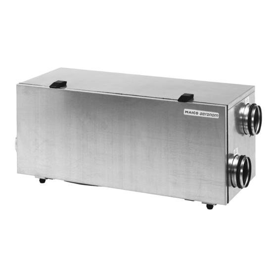
2. The ventilation system 2.1 Overview 2. The ventilation system 2.1 Overview The top pictures on the left show the components of the ventilation system (ventilation unit , here shown as a right-hand version, supplied / operator unit as an accessory). The lower picture on the left, shows the schematic construction of a ventilation system, combined with additional system components. -
Seite 32: System Features
2. The ventilation system 2.3 System features 2.3 System features Operation of the ventilation unit with the operator panel (2). The operator unit shown here has a timer for automatic switching between fan level 1 and 2, as well as a filter change display. Degree of heat provision up to 90%. -
Seite 33: System Accessories
2. The ventilation system 2.5 System accessories 2.5 System accessories Operator unit Replacement filter set Sound absorber Electric air heater with own controller Air-water heating register (for air reheating) Electronic temperature controller 2.6 Safety devices The ventilation unit is fitted with a safety switch. This is activated when the front door is folded down. - Seite 34 2. The ventilation system 2.8 Ventilation unit – Overview...
-
Seite 35: Ventilation Unit
2. The ventilation system 2.8 Ventilation unit 2.8 Ventilation unit R = Ventilation unit, right-hand version L = Ventilation unit, left-hand version A = Outside air: Fresh air that is drawn in from the outside. B = Supply air: Warmed, fresh air that flows into the living area. C = Exhaust air: Used, warm air that is extracted from the living area. -
Seite 36: Cleaning, Maintenance
3. Cleaning, maintenance 3.1 Safety instructions 3. Cleaning, maintenance 3.1 Safety instructions Disconnect the ventilation unit as well as all other components from the mains supply before carrying out any cleaning and maintenance work (switch off mains fuse). CAUTION Risk of injury if the front door is folded down. Always hold the front door in place with one hand while opening the quick-release clips so that it doesn't fold down suddenly. -
Seite 37: Cleaning The Ventilation Unit
3. Cleaning, maintenance 3.3 Cleaning the ventilation unit 3.3 Cleaning the ventilation unit Depending on the level of contamination, we recommend: Cleaning the inside of the unit once a year Cleaning the heat exchanger once a year Cleaning the condensation run-off and the siphon twice a year Cleaning the heat exchanger (see Chapter 2.8, Item 7), cleaning the inside of the ventilation unit 1. -
Seite 38: Assembling The Ventilation Unit
4. Assembling the ventilation unit (Specialist installer) 4.1 Before the installation 4. Assembling the ventilation unit 4.1 Before the installation / Installation plan Transport Make sure that the unit is not damaged or knocked over during transport. Pay attention to the valid safety and accident prevention regulations. The manufacturer offers no guarantee and assumes no liability for damage CAUTION caused by incorrect transport or storage. -
Seite 39: Installing The Ventilation Unit
4. Assembling the ventilation unit (Specialist installer) 4.2 Installing the ventilation unit 4.2 Installing the ventilation unit 1. Place the ventilation unit in position and make sure that it is horizontal. 2. Make sure that there is enough free space in front of the unit for installation and operation. -
Seite 40: Carrying Out The Electrical Connection
4. Assembling the ventilation unit (Specialist installer) 4.5 Carrying out the electrical connection 4.5 Carrying out the electrical connection The electrical connection of the ventilation unit and the additional components may only be done by a qualified electrician. The ventilation unit may only be operated using the rated voltage shown DANGER on the rating plate. -
Seite 41: Wiring Diagram Example Connection With Operator Unit
4. Assembling the ventilation unit (Specialist installer) 4.6 Wiring diagram 4.6 Wiring diagram Example connection with operator unit Unit off Daytime operation, fan level 2 Nighttime operation, fan level 1 Automatic operation, fan level 1/2 Party operation, fan level 3 Potentiometer for adjusting the exhaust air volumetric 230 VAC connecting cable Switchable power unit with volumetric flow regulation... -
Seite 42: Volumetric Flow
4. Assembling the ventilation unit (Specialist installer) 4.7 Settings at the switchable power unit 4.7 Settings at the switchable power unit DIP switch settings The ventilation unit is fitted with an electronic volumetric flow regulation for a constant air flow. The unit's electronics adjusts the speeds of both fans to hold the air quantity constant, irrespective of the system pressure. - Seite 43 There is a potentiometer (P2) on the ventilation unit's switchable power unit for adjusting the exhaust air volumetric flow to the supply air volume flow. This setting may only be made by MAICO Customer service. Anticlockwise = Reducing the exhaust air volumetric flow...
-
Seite 44: Technical Data
5. Technical Data 5. Technical Data Right-hand version ca.48 ca.48 EXHAUST AIR OUTSIDE AIR OUTGOING AIR SUPPLY AIR Condensation drain El. connections EXHAUST AIR OUTSIDE AIR SUPPLY AIR OUTGOING AIR Clips Left-hand version View from the front ca.48 ca.48 El.connections EXHAUST AIR OUTSIDE AIR SUPPLY AIR... - Seite 45 5. Technical Data Housing dimensions with connectors and feet (W x H x D) 1070 x 463 x 400 mm Construction Sandwich construction with 20 mm thermal insulation Material/colour Sheet steel, galvanised Duct connection DN 125 mm Condensation connection ½" hose Protection class Degree of protection IP 00...
-
Seite 46: Disposal
6. Disposal 6. Disposal Packaging: Transport and protective packaging is, to a large extent, made of recyclable materials. Dispose of the packaging materials in accordance with local regulations. Take the wooden pallets, for example, to your local recycling point. Filters: Dispose of the filters with normal rubbish. Old units: The old unit must be dismantled by a specialist company and disposed of correctly. - Seite 48 Maico Elektroapparate-Fabrik GmbH Phone Nos.: Fax: + 49 7720 694 177 Steinbeisstraße 20 Sales + 49 7720 694 359 www.maico.de 78056 Villingen-Schwenningen Order processing + 49 7720 694 343 sales@maico.de Germany Tech. advice: + 49 7720 694 392...
- Seite 49 Récupérateur de chaleur WS 150 Notice de montage, d'utilisation et d'entretien www. m aic o-v ent ilat oren.c om...
- Seite 50 Remarques importantes relatives à cette notice Remarques importantes relatives à cette notice Lisez attentivement et intégralement cette notice avant d’utiliser, de monter ou de raccorder l’appareil de ventilation. Conservez ces instructions soigneusement. Remarques, Utilisation : les premiers chapitres s’adressent à l’utilisateur. Voici quelques à...
- Seite 51 Sommaire Sommaire Page Introduction ..............Eléments fournis .............. Symboles figurant dans cette notice d'instructions ..Domaines d'application, finalité ........Directives relatives à une utilisation avec un foyer ..Consignes de sécurité ........... Le système de ventilation ..........Vue d'ensemble ..............Fonction ................
-
Seite 52: Introduction
1. Introduction 1.1 Scope of delivery 1.2 Symboles figurant dans cette notice d'instructions Danger de mort ! Le non respect peut entraîner des blessures corporelles graves, voire la mort. DANGER Risque de blessure! Le non-respect peut entraîner des blessures corporelles graves. -
Seite 53: Consignes De Sécurité
1. Introduction 1.5 Consignes de sécurité 1.5 Consignes de sécurité 1. Installez exclusivement l'appareil de ventilation conformément à la destination décrite précédemment. 2. Une fois l'installation effectuée, demandez à votre installateur de vous AVERTISSEMENT former à l'utilisation de l'appareil et du module de commande. 3. -
Seite 54: Le Système De Ventilation
2. Le système de ventilation... -
Seite 55: Vue D'ensemble
6. Respectez impérativement les exigences relatives à la protection AVERTISSEMENT contre l'incendie. 19. Les modifications et transformations apportées sur l'appareil de ventilation sont rigoureusement interdites et dégagent MAICO de toute responsabilité ou garantie. 2. Le système de ventilation 2.1 Vue d'ensemble L'illustration en haut à... -
Seite 56: Caractéristiques Du Système
2. Le système de ventilation 2.3 Caractéristiques du système 2.3 Caractéristiques du système Commande de l'appareil de ventilation avec module de commande (2). Le module de commande ici représenté dispose d'une minuterie destinée au mode automatique entre les niveaux de ventilateur 1 et 2 et d'un affichage du remplacement du filtre. -
Seite 57: Accessoires Du Système
2. Le système de ventilation 2.5 Accessoires du système 2.5 Accessoires du système Module de commande Kit filtres de rechange Silencieux Réchauffeur d'air électrique à commande individuelle Registre de tirage air-eau (pour le réchauffage de l'air) Régulateur électronique de température 2.6 Dispositifs de sécurité... - Seite 58 2. Le système de ventilation 2.8 Appareil de ventilation – Vue d'ensemble...
-
Seite 59: Appareil De Ventilation
2. Le système de ventilation 2.8 Appareil de ventilation 2.8 Appareil de ventilation R = Appareil de ventilation en version à droite L = Appareil de ventilation en version à gauche A = Air extérieur: air frais aspiré à l'extérieur. B = Air entrant: air frais chauffé... -
Seite 60: Nettoyage, Entretien
3. Nettoyage, entretien 3.1 Consignes de sécurité 3. Nettoyage, entretien 3.1 Consignes de sécurité Pour les travaux de nettoyage et d'entretien, coupez l'appareil de ventilation et tous les composants complémentaires du secteur (déconnexion fusible secteur). PRUDENCE Risque de blessure lié à la porte avant rabattable: en ouvrant les fermetures de serrage rapide, maintenez toujours fermement la porte avant avec la main, afin d'éviter que celle-ci ne se rabatte brutalement. -
Seite 61: Nettoyage De L'appareil De Ventilation
3. Nettoyage, entretien 3.3 Nettoyage de l'appareil de ventilation 3.3 Nettoyage de l'appareil de ventilation En fonction du degré d'encrassement, nous recommandons: un nettoyage interne annuel un nettoyage annuel de l'échangeur de chaleur un nettoyage bi-annuel de l'écoulement de condensat et du siphon Nettoyer l'échangeur de chaleur (cf. -
Seite 62: Montage De L'appareil De Ventilation
4. Montage de l'appareil de ventilation (installateur spécialisé) 4.1 Avant l'installation 4. Montage de l'appareil de ventilation 4.1 Avant l'installation / Schéma d'encombrement Transport Lors du transport, veillez à ce que l'appareil ne soit ni endommagé ni renversé. Respectez les directives relatives à la sécurité et à la prévention des PRUDENCE accidents en vigueur. -
Seite 63: Mise En Place De L'appareil De Ventilation
4. Montage de l'appareil de ventilation (installateur spécialisé) 4.2 Mise en place de l'appareil de ventilation 4.2 Mise en place de l'appareil de ventilation 1. Installez l'appareil de ventilation sur le lieu de montage et positionnez-le à l'horizontale. 2. Pensez à laisser un espace libre suffisant devant l'appareil pour le montage et le fonctionnement: La porte avant doit pouvoir se rabattre et les filtres et l'échangeur de chaleur être démontés. -
Seite 64: Réalisation Du Raccordement Électrique
4. Montage de l'appareil de ventilation (installateur spécialisé) 4.5 Réalisation du raccordement électrique 4.5 Réalisation du raccordement électrique Le raccordement électrique de l'appareil de ventilation et des composants supplémentaires est exclusivement réservé à des électriciens qualifiés. Faites exclusivement fonctionner l'appareil de ventilation à la tension de DANGER service indiquée sur la plaque signalétique. -
Seite 65: Plan De Câblage: Exemple De Raccordement Avec Module De Commande
4. Montage de l'appareil de ventilation (installateur spécialisé) 4.6 Plan de câblage: Exemple de raccordement 4.6 Plan de câblage: Exemple de raccordement avec module de commande Appareil à l’arrêt Mode jour, niveau de ventileur 2 Mode nuit, niveau de ventilateur 1 Mode automatique, niveau de ventilateur ½... -
Seite 66: Réglages Sur L'alimentation À Découpage
4. Montage de l'appareil de ventilation (installateur spécialisé) 4.7 Réglages sur l'alimentation à découpage 4.7 Réglages sur l'alimentation à découpage Réglages des interrupteurs DIP L'appareil de ventilation est équipé d'une régulation électronique du débit volumique garantissant un flux d'air constant. L'électronique de l'appareil ajuste la vitesse de rotation des deux ventilateurs, afin de maintenir la quantité... - Seite 67 4. Montage de l'appareil de ventilation (installateur spécialisé) 4.7 Réglages sur l'alimentation à découpage Interrupteurs DIP 3 + 4 pour le niveau de ventilation 2 (ventilation normale /mode jour) Débit d'air Interrupteur 3 Interrupteur 4 1= ON 0 = OFF 135 m³/h 120 m³/h 100 m³/h (réglage...
-
Seite 68: Caractéristiques Techniques
5. Caractéristiques techniques 5. Caractéristiques techniques Version à droite Air extérieur Air rejeté Air extérieur Air rejeté Version à gauche Air extérieur Air rejeté Air rejeté Air extérieur... - Seite 69 5. Caractéristiques techniques Dimensions du boîtier avec supports et pieds (L x H x P) 1070 x 463 x 400 mm Type de construction Construction sandwich avec isolation thermique de 20 mm Matériau/couleur Tôle d'acier, galvanisée Raccords gaine ronde DN 125 mm Raccordement pour condensat Tuyau ½"...
-
Seite 70: Elimination
6. Élimination 6. Élimination Emballage : l’emballage de protection et de transport est essentiellement composé de matériaux recyclables. Eliminez les matériaux d’emballage dans le respect des prescriptions locales. Rapportez p. ex. la palette de bois à votre site de matériaux recyclables en vue de son recyclage. - Seite 72 Maico Elektroapparate-Fabrik GmbH Phone Nos.: Fax: + 49 7720 694 177 Steinbeisstraße 20 Sales + 49 7720 694 359 www.maico.de 78056 Villingen-Schwenningen Order processing + 49 7720 694 343 sales@maico.de Allemagne Tech. advice: + 49 7720 694 392...