Herunterladen Inhalt Inhalt Diese Seite drucken
Inhaltsverzeichnis

Werbung

Verfügbare Sprachen
  • DE

Verfügbare Sprachen

  • DEUTSCH, seite 35
PX 110 - PX 120
PUISSANCEMÈTRE
POWER METER
WATTMETER
WATTOMETRI
VATÍMETROS

Werbung

Inhaltsverzeichnis
loading

Inhaltszusammenfassung für Metrix PX 110

  • Seite 1 PX 110 - PX 120 PUISSANCEMÈTRE POWER METER WATTMETER WATTOMETRI VATÍMETROS...
  • Seite 2 PX 110 - PX 120 PUISSANCEMÈTRE POWER METER WATTMETER WATTOMETRI VATÍMETROS Notice de fonctionnement page 6 Chapitre User's manual page 21 Chapitre Bedienungsanleitung Seite 36 Kapitel Libretto d'Istruzioni pagina 51 Capitolo Manual de Instrucciones página 66 Capítulo Copyright © 688 919 A00 - Ed 1 - 03/2001...
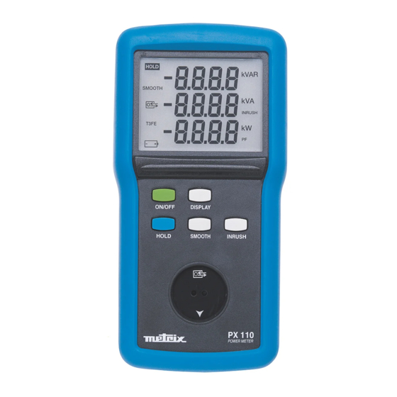
  • Seite 3 HOLD kVAR SMOOTH INRUSH ON/OFF DISPLAY HOLD SMOOTH INRUSH PX 110 POWER METER Se reporter au § 2. Description See § 2. Description Siehe § 2. Beschreibung Vedi § 2. Descrizione Remitirse al § 2. Descripción Puissancemètres...
  • Seite 4 HOLD kVAR SMOOTH INRUSH T3FE ON/OFF DISPLAY T3FE HOLD SMOOTH INRUSH PX 120 POWER METER Se reporter au § 2. Description See § 2. Description Siehe § 2. Beschreibung Vedi § 2. Descrizione Remitirse al § 2. Descripción Puissancemètres...
  • Seite 5: Inhaltsverzeichnis

    SOMMAIRE 1. INSTRUCTIONS GENERALES ....................7 1.1. Précautions et mesures de sécurité .................. 7 1.2. Dispositifs de protection ..................... 8 1.3. Garantie ..........................8 1.4. Réparation et vérification métrologique ................9 1.5. Déballage - Réemballage ....................9 2. DESCRIPTION DE L'APPAREIL ....................9 2.1.
  • Seite 6: Instructions Generales

    Chapitre I INSTRUCTIONS GENERALES Vous venez d’acquérir un wattmètre PX 110 ou PX 120 et nous vous remercions de votre confiance. Cet appareil est conforme à la norme de sécurité NF EN 61010 Ed. 95, relative aux instruments de mesure électroniques. Vous devez respecter, pour votre sécurité et celle de l'appareil, les consignes décrites dans cette notice.
  • Seite 7: Dispositifs De Protection

    Chapitre I 1.1.3 Symboles Les symboles suivants sont utilisés : ATTENTION : Référez-vous à la notice. Une utilisation incorrecte peut endommager l'appareil et mettre en jeu la sécurité de l'utilisateur. Cet appareil est protégé par une isolation double ou une isolation renforcée. Il ne nécessite pas de raccordement à...
  • Seite 8: Réparation Et Vérification Métrologique

    DESCRIPTION DE L'APPAREIL Les wattmètres PX 110 et PX 120 permettent la mesure en alternatif et continu des puissances, des tensions et des courants. Ils ont été conçus particulièrement pour les lycées d'enseignement généraux et techniques, les installateurs et les services de maintenance.
  • Seite 9: Boîtier

    Douilles de sécurité pour l'entrée des courants à mesurer Douilles de sécurité pour l'entrée des tensions à mesurer Touches de commande (5 pour le PX 110 et 6 pour le PX120) ON / OFF Mise en / hors service DISPLAY Permet l'accès aux différents écrans, par appuis successifs...
  • Seite 10: Fonction Inrush

    Chapitre III 2.2.2 Affichage des symbole des fonctions HOLD Indique l'utilisation de la touche correspondante (voir § 2.1) SMOOTH Indique l'utilisation de la touche correspondante (voir § 2.1) Indique qu'une communication est activée (voir § 3.6) T3FE Indique l'utilisation de la touche correspondante en mesure Triphasé 3 Fils Equilibrés (uniquement sur PX 120) Indique que l'autonomie des piles est <...
  • Seite 11: Mesure De Tensions (V)

    Chapitre III Mesure de tensions 1. Appuyer sur la touche ON/OFF : le premier écran apparait 2. Brancher les cordons de mesure sur les bornes mesure de tension de l’appareil (à droite), en respectant les polarités indiquées : cordon rouge sur la borne "+" et cordon noir sur la borne "COM".
  • Seite 12: Mesures De Puissance

    Chapitre III 3.3.1 Conditions de référence particulières En DC : Composante AC 0,1% du signal DC . En AC : Signal sinusoïdal (THD < 0,1%). 3.3.2 Caractéristiques en mode normal et SMOOTH Gamme d’affichage 10 A (1) Etendue de mesure 10 mA...1,999 A 2,00...9,99 A Précision en AC...
  • Seite 13 Chapitre III Fig 4.4.2 Schéma de branchement en Triphasé 3 Fils Equilibrés (uniquement PX 120) 3.4.1 Conditions de référence particulières En DC : Composante AC < 0,1% du signal DC. En AC : - Signaux sinusoïdaux - PF = 1 - Fréquence : 50 Hz 3.4.2 Mesures de puissance active...
  • Seite 14 Chapitre III 3.4.3 Mesures de puissance apparente 1. Appuyer sur la touche ON/OFF : le premier écran apparait 2. Brancher les cordons de mesure sur les bornes mesure de courant de l’appareil (à gauche), en respectant les polarités indiquées : cordon rouge sur la borne "+" et cordon noir sur la borne "COM".
  • Seite 15: Communication (Option)

    Chapitre III Appuyer sur la touche DISPLAY, pour afficher le 2 ème écran : - l'afficheur numérique du haut indique la valeur de la puissance réactive et l'unité correspondante (VAR). Caractéristiques Gamme d’affichage 1000 VAR 6 kVAR Etendue de mesure 10,0 VAR...999,9 VAR 1000 VAR...5999 kVAR Précision...
  • Seite 16: Alimentation Secteur (Option)

    Chapitre IV - Calibrage de l'appareil en usine ou agence Manumesure - Avec un logiciel d'exploitation (en option) installé sur un PC, il est possible de lire et d'enregistrer les mesures des wattmètres selon le mode de fonctionnement, il est possible de : - visualiser sur l'écran du PC, une ou deux grandeurs parmis six, - de faire des impressions d'écran, - de transférer des fichiers de mesure vers un fichier Excel et de les stocker.
  • Seite 17: Conformité Aux Normes

    Chapitre IV Altitude - Fonctionnement : ≤ 2000 m - Stockage : ≤ 10000 m Etanchéité : indice de protection IP 54 (selon EN 60529, éd. 2000) (IP2X électrique pour les bornes) Conformité aux normes Sécurité électrique (selon EN 61010-1, éd. 95) - Double isolation : - Catégorie d'installation : III - Degré...
  • Seite 18: Accessoires

    Nota : Le terme Puissance fait référence à la puissance active et ses grandeurs associées Q, S et PF. ACCESSOIRES Livrés avec les wattmètres PX 110 / PX 120 - 2 jeux de câbles de sécurité - 2 pointes de touche noir et rouge...
  • Seite 19: Maintenance

    Chapitre VI MAINTENANCE Pour la maintenance, utilisez seulement les pièces de rechange qui ont été spécifiées. Le fabricant ne pourra être tenu pour responsable de tout accident survenu suite à une réparation effectuée en dehors de son service après-vente ou des réparateurs agréés.
  • Seite 20 ENGLISH CONTENTS 1. GENERAL INSTRUCTIONS ....................22 1.1 Precautions and safety measures .................. 22 1.2 Protective systems ......................23 1.3 Guarantee ........................23 1.4 Repair and metrological verification ................24 1.5 Unpacking - Repacking ....................24 2. DESCRIPTION OF THE INSTRUMENT .................. 24 2.1 Casing ..........................
  • Seite 21: General Instructions

    Chapter I GENERAL INSTRUCTIONS Thank you for purchasing this PX 110 or PX 120 wattmeter. This instrument complies with the NF EN 61010 Ed. 95 safety standard concerning electronic measurement instruments. For your own safety and to prevent damage to the instrument, it is essential to respect the instructions given in this manual.
  • Seite 22: Protective Systems

    Chapter I 1.1.3 Symbols The following symbols are used: ATTENTION : Consult the manual. Incorrect use may damage the instrument and endanger the user. This appliance is protected by dual insulation or reinforced insulation. It does not have to be connected to an earth protection terminal for electrical safety. 1.1.4 Instructions * Before opening the instrument, disconnect if from all sources of electrical current and...
  • Seite 23: Repair And Metrological Verification

    DESCRIPTION OF THE INSTRUMENT The PX 110 and PX 120 wattmeters can be used to measure AC and DC power levels, voltages and currents. They have been designed specifically for general and technical colleges, installers and maintenance departments.
  • Seite 24: Casing

    (see the diagrams at the beginning of this operating manual) Safety sockets for input of the currents to be measured Safety sockets for input of the voltages to be measured Control keys (5 for the PX 110 and 6 for the PX120) ON / OFF Activation / shutdown DISPLAY...
  • Seite 25: Inrush Function

    Chapter III 2.2.2 Display of the function symbols HOLD Indicates use of the corresponding key (see § 2.1) SMOOTH Indicates use of the corresponding key (see § 2.1) Indicates that communication is activated (see § 3.6) T3FE Indicates use of the corresponding key for three-phase/balanced wires measurement (only on PX 120) Indicates that the remaining battery charge life is <...
  • Seite 26: Voltage Measurements (V)

    Chapter III Voltage measurements 1. Press the ON/OFF key: the first screen appears 2. Connect the measurement leads to the instrument’s voltage measurement terminals (on the right), complying with the polarities indicated: red lead on the “+” terminal and black lead on the “COM”...
  • Seite 27: Characteristics In Inrush Mode

    Chapter III 3.3.1 Specific reference conditions DC: AC component 0.1% of the DC signal AC: Sinusoidal signal (THD < 0.1%) 3.3.2 Characteristics in normal and SMOOTH modes Display range 10 A (1) Measuring range 10 mA...1.999 A 2.00...9.99 A Accuracy for AC 0.5% reading ±2 cts +1 mA 0.5% of reading ±2 cts Accuracy for DC...
  • Seite 28 Chapter III Fig 4.4.2 Three-phase/balanced wires (T3FE) connection diagram (PX 120 only) 3.4.1 Specific reference conditions DC: AC component < 0.1% of the DC signal AC: - Sinusoidal signals - PF = 1 - Frequency: 50 Hz 3.4.2 Active power measurements 1.
  • Seite 29 Chapter III 3.4.3 Apparent power measurements 1. Press the ON/OFF key: the first screen appears 2. Connect the measurement leads to the instrument’s current measurement terminals (on the left), complying with the polarities indicated: red lead on the “+” terminal and black lead on the “COM”...
  • Seite 30: Communication (Option)

    Chapter III Press the DISPLAY key to display the 2nd screen: - the upper digital display indicates the value of the reactive power and the corresponding unit (VAR). Characteristics Display range 1000 VAR 6 kVAR Measuring range 10.0 VAR...999.9 VAR 1000 VAR...5999 kVAR Accuracy 2% of reading ±2 cts...
  • Seite 31: Mains Power Supply (Option)

    Chapter IV - Calibration of the instrument in the factory or at a Manumesure branch. - With operating software (available as an option) installed on a PC, it is possible to read and record the wattmeter measurements; depending on the operating mode, you can: - view one or two of six parameters on the PC screen, - print out the contents of the screen, - transfer measurement files into an Excel file and store them.
  • Seite 32: Compliance With Norms

    Chapter IV Altitude - Operation: ≤ 2,000 m - Storage ≤ 10,000 m Impermeability: protection index IP 54 (according to EN 60529, ed. 2000) (IP2X electrical protection for the terminals) Compliance with norms Electrical safety (as per EN 61010-1 ed. 95) - Dual insulation: - Installation category: III - Pollution level: 2...
  • Seite 33: Accessories

    Chapter V Operating Parameters Influence parameter Typical error Max error range influenced Current 0,2% 0,5% Peak factor 1 to 5 Voltage 0,2% 0,2% Active power 0,3% < 1% 0,5 < PF < 1 Reactive power < 2% ±10 VAR Active power 0,7% <...
  • Seite 34: Maintenance

    Chapter VI MAINTENANCE Only use specified spare parts for maintenance purposes. The manufacturer cannot accept any responsibility for accidents occurring following repairs carried out outside its after-sales department or approved maintenance network. Replacing the batteries Disconnect the leads from the instrument Press the OFF key Unscrew the “quarter-turn screw”...
  • Seite 35 DEUTSCH INHALT 1. ALLGEMEINE ANWEISUNGEN ..................... 37 1.1 Vorsichts- und Sicherheitsmaßnahmen ................37 1.2 Schutzvorrichtungen ....................... 38 1.3 Garantie ........................... 38 1.4 Reparatur und messtechnische Überprüfung ..............39 1.5 Auspacken – Verpacken ....................39 2. BESCHREIBUNG DES GERÄTS ................... 39 2.1 Gehäuse ..........................
  • Seite 36: Allgemeine Anweisungen

    Kapitel I ALLGEMEINE ANWEISUNGEN Wir danken Ihnen für das Vertrauen, dass Sie uns mit dem Kauf dieses Wattmeters PX 110 oder PX 120 entgegengebracht haben. Dieses Gerät entspricht der Sicherheitsnorm NF EN 61010 Ausg. 95 für elektronische Messgeräte. Zu Ihrer eigenen Sicherheit und der des Geräts sollten Sie die in der vorliegenden Bedienungsanleitung beschriebenen Anweisungen befolgen.
  • Seite 37: Schutzvorrichtungen

    Kapitel I 1.1.3 Symbole Die folgenden Symbole werden verwendet: ACHTUNG : Siehe Bedienungsanleitung. Falsche Bedienung kann zu Schäden am Gerät führen und die Sicherheit des Benutzers gefährden. Das Gerät ist schutzisoliert bzw. durch eine verstärkte Isolierung geschützt. Der Anschluss an einen Erdleiter ist für die Gewährleistung der elektrischen Sicherheit nicht erforderlich.
  • Seite 38: Reparatur Und Messtechnische Überprüfung

    -Spannungen und -Strömen. Sie wurden insbesondere für allgemeine und technische Schulen, für Installateure und für Wartungsdienste entwickelt. Das PX 110 ist ein Wattmeter nur für einphasige Messungen, das PX 120 verfügt über die Möglichkeit zur dreiphasigen Leistungsmessung nur im symmetrischen 3 Leiter-System. Beide Modelle ermöglichen Messungen in allen vier Quadranten.
  • Seite 39: Gehäuse

    (siehe Schemazeichnungen am Anfang dieser Bedienungsanleitung) Sicherheitsbuchsen für den Eingang der zu messenden Ströme Sicherheitsbuchsen für den Eingang der zu messenden Spannungen Steuertasten (5 beim PX 110 und 6 beim PX120) ON / OFF Ein- / Ausschalten DISPLAY Erlaubt durch mehrmaliges Drücken den Zugriff auf verschiedene Bildschirme T3FE Ermöglicht den Zugriff auf die Messungen der Leistung und des...
  • Seite 40: Anzeige Der Funktionssysmbole

    Kapitel III 2.2.2 Anzeige der Funktionssysmbole HOLD Zeigt die Verwendung der entsprechenden Taste an (siehe § 2.1) SMOOTH Zeigt die Verwendung der entsprechenden Taste an (siehe § 2.1) Zeigt an, dass eine Kommunikation aktiviert wurde (siehe § 3.6) T3FE Zeigt die Verwendung der entsprechenden Taste bei dreiphasiger Messung im symmetrischen Leiter-System an (nur beim PX 120) Zeigt an, dass die Betriebsdauer der Batterien <...
  • Seite 41: Spannungsmessung (V)

    Kapitel III Spannungsmessung 1. Drücken Sie die Taste ON/OFF: Der erste Bildschirm erscheint. 2. Schließen Sie die Messleitungen unter Beachtung der Polarität an die Klemmen zur Spannungsmessung des Geräts an (rechts): rote Leitung an die Klemme „+“ und schwarze Leitung an die Klemme „COM“. 3.
  • Seite 42: Technische Daten Im Modus Inrush

    Kapitel III 3.3.1 Besondere Bezugsbedingungen Bei DC: Komponente AC < 0,1 % des DC-Signals Bei AC: Sinusförmiges Signal (THD < 0,1 %) 3.3.2 Technische Daten in den Modi Normal und SMOOTH 10 A (1) Anzeigebereich Messbereich 10 mA...1,999 A 2,00...9,99 A Genauigkeit bei AC 0,5 % Anz.
  • Seite 43: Wirkleistungsmessung

    Kapitel III Abb. 4.4.2 Anschlussschema für dreiphasige Messung im symmetrischen 3 Leitersystem (nur PX 120) 3.4.1 Besondere Bezugsbedingungen Bei DC: Komponente AC < 0,1 % des DC-Signals Bei AC: - Sinusförmige Signale - PF = 1 - Frequenz: 50 Hz 3.4.2 Wirkleistungsmessung 1.
  • Seite 44: Scheinleistungsmessung

    Kapitel III 3.4.3 Scheinleistungsmessung 1. Drücken Sie die Taste ON/OFF: Der erste Bildschirm erscheint. 2. Schließen Sie die Messleitungen unter Beachtung der Polarität an die Klemmen zur Strommessung des Geräts an (links): rote Leitung an die Klemme „+“ und schwarze Leitung an die Klemme „COM“.
  • Seite 45: Messung Des Leistungsfaktors Pf

    Kapitel III Technische Daten Anzeigebereich 1000 VAR 6 kVAR Messbereich 10,0 VAR...999,9 VAR 1000 VAR...5999 kVAR Genauigkeit 2 % Anz. ± 2 Digits 2 % Anz. ± 2 Digits Auflösung 0,1 VAR 1 VAR Stabilität der Anzeige 5 Digits im Normalmodus 2 Digits im Modus SMOOTH Ansprechzeit 400 ms im Normalmodus...
  • Seite 46: Netzteil (Option)

    Kapitel IV - Kalibrierung des Geräts im Werk oder in einer Manumesure Niederlassung - Mit einer auf einem PC installierten Auswertungssoftware (optional) können die Messwerte des Wattmeters je nach Betriebsart eingelesen und gespeichert werden. Möglich sind: - die Anzeige von einer oder zwei Größen von sechs möglichen auf dem Bildschirm des PC, - die Durchführung eines Bildschirmausdrucks, - die Übertragung der Messwertdateien in eine Excel-Datei und deren Speicherung.
  • Seite 47: Einhaltung Der Normen

    Kapitel IV Höhe - Betrieb: < 2.000 m - Lagerung: < 10.000 m Dichtheit: Schutzart IP 54 (gemäß EN 60529, Ausg. 2000) (IP2X elektrisch für die Klemmen) Einhaltung der Normen Elektrische Sicherheit (gemäß EN 61010-1, Ausg. 95) - Schutzisolierung: - Überspannungskategorie: III - Verschmutzungsgrad: 2 - Betriebsspannung: 600 V Elektromagnetische Verträglichkeit (EN 61326-1 Ausg.
  • Seite 48: Zubehör

    Kapitel V Beeinflusste Einflussgröße Betriebsbereich Typischer Fehler Max. Fehler Größen Strom (THD = 40%) 0,2% 0,5% Oberwellen Spannung (THD = 20%) 0,2% 0,5% Strom 0,2% 0,5% Scheitelfaktor 1 bis 5 Spannung 0,2% 0,2% Wirkleistung 0,3% < 1% 0,5 < PF < 1 Blindleistung <...
  • Seite 49: Wartung

    Kapitel VI WARTUNG Für die Wartung sind ausschließlich die angegebenen Ersatzteile zu verwenden. Der Hersteller kann nicht für Unfälle haftbar gemacht werden, die auf eine Reparatur zurückzuführen sind, die nicht von seinem Kundendienst oder einem zugelassenen Reparaturservice durchgeführt wurde. Batteriewechsel Klemmen Sie die Leitungen vom Gerät ab.
  • Seite 50 ITALIANO SOMMARIO 1. ISTRUZIONI GENERALI ......................52 1.1 Precauzioni e misure di sicurezza .................. 52 1.2 Dispositivi di protezione ....................53 1.3 Garanzia .......................... 53 1.4 Riparazione e verifica metrologica .................. 54 1.5 Sballatura - Reimballaggio ....................54 2. DESCRIZIONE DELL’APPARECCHIO ................... 54 2.1 Scatola ..........................
  • Seite 51: Istruzioni Generali

    Capitolo I ISTRUZIONI GENERALI Avete appena acquistato un wattmetro PX 110 o PX120 e vi ringraziamo per la vostra fiducia Il presente apparecchio è conforme alla norma di sicurezza NF EN 61010 Ed. 95, relativa agli strumenti di misura elettronici. Per la sicurezza vostra e dell’apparecchio, dovete rispettare le raccomandazioni riportate nel presente libretto.
  • Seite 52: Norme Cautelari

    Capitolo I 1.1.3 Simboli Sono utilizzati i seguenti simboli: Attenzione: Vedi il libretto. Uno utilizzo non corretto può danneggiare l’apparecchio e porre in gioco l’incolumità dell’utilizzatore. Il presente apparecchio è protetto da doppio isolamento. Non richiede collegamento al morsetto di terra di protezione per garantire la sicurezza elettrica 1.1.4 Norme cautelari * Prima di aprire l’apparecchio , è...
  • Seite 53: Riparazione E Verifica Metrologica

    DESCRIZIONE DELL’APPARECCHIO I wattmetri PX 110 e PX 120 permettono la misura delle potenze, delle tensioni e delle correnti. Essi sono stati progettati specificatamente per l’insegnamento generale e tecnico, per gli installatori e per i servizi di manutenzione.
  • Seite 54: Scatola

    Boccole di sicurezza per l’entrata delle correnti da misurare Boccole di sicurezza per l’entrata delle tensioni da misurare Tasti di comando (5 per il PX 110 e 6 per il PX120) ON / OFF Messa in servizio / fuori servizio DISPLAY Permette l’accesso ai differenti schermi, con pressioni successive...
  • Seite 55: Funzione Inrush

    Capitolo III 2.2.2 Visualizzazione dei simboli delle funzioni HOLD Indica l’utilizzazione del tasto corrispondente (vedi § 2.1) SMOOTH Indica l’utilizzazione del tasto corrispondente (vedi § 2.1) Indica che una comunicazione è attivata (vedi § 3.6) T3FE Indica l’utilizzazione del tasto corrispondente in misura Trifase 3 Fili Equilibrati (unicamente su PX 120) Indica che l’autonomia delle pile è...
  • Seite 56: Misura Di Tensione (V)

    Capitolo III Misura di tensione 1. Premere sul tasto ON/OFF : appare il primo schermo 2. Collegare i cavi di misura sui morsetti di misura di tensione dello strumento (a destra), rispettando le polarità indicate : cavo rosso sul morsetto “+” e cavo nero sul morsetto “COM”.
  • Seite 57: Caretteristiche In Modo Normale E Smooth

    Capitolo III 3.3.1 Condizioni di riferimento particolari. In DC : Componente AC < 0,1% del segnale DC In AC : Segnale sinusoidale (THD < 0,1%) 3.3.2. Caretteristiche in modo normale e SMOOTH Gamma di visualizzazione 10 A (1) Escursione di misura 10 mA...1,999 A 2,00...9,99 A Precisione in AC...
  • Seite 58 Capitolo III Fig 4.4.2 Schema di collegamento in Trifase 3 Fili Equilibrati (unicamente PX 120) 3.4.1 Condizioni di riferimento particolari. In DC : Componente AC < 0,1% del segnale DC In AC : - Segnali sinusoidali - PF = 1 - Frequenza: 50 Hz 3.4.2 Misure di potenza attiva...
  • Seite 59 Capitolo III 3.4.3 Misure di potenza apparente 1. Premere sul tasto ON/OFF : appare il primo schermo 2. Collegare i cavi di misura sui morsetti di misura di corrente dello strumento (a sinistra), rispettando le polarità indicate : cavo rosso sul morsetto “+” e cavo nero sul morsetto “COM”.
  • Seite 60: Comunicazione (Optional)

    Capitolo III Caratteristiche Portata 1000 VAR 6 kVAR Campo di misura 10,0 VAR...999,9 VAR 1000 VAR...5999 kVAR Precisione 2% L ±2 pt 2% L ±2 pt Risoluzione 0,1 VAR 1 VAR Stabilità della visualizzazione 5 pt in modo normale 2 pt in modo SMOOTH Tempi di risposta 400 ms in modo normale di visualizzazione...
  • Seite 61: Alimentazione Rete Elettrica (Optional)

    Capitolo IV - visualizzare sullo schermo del PC, una o due grandezze fra sei, - realizzare delle impressioni dello schermo, - trasferire i file di misura verso un file di tipo Excel. Caratteristiche - 1 bit di start - 8 bits di dati - niente parità...
  • Seite 62: Conformità Alle Norme

    Capitolo IV Altitudine - Funzionamento: ≤ 2.000 m - Stoccaggio : ≤ 10.000 m Ermeticità: indice di protezione IP 54 (secondo EN 60529, ed. 2000) (IP2X elettrico per i morsetti) Conformità alle norme Sicurezza elettrica (secondo EN 61010-1, ed. 95) - Doppio isolamento: - Categoria d’impianto: III - Livello di inquinamento: 2...
  • Seite 63: Accessori

    Capitolo V Grandezze Grandezze Portata Errore Tipico Errore Massimo di influenza influenzate Corrente (THD = 40%) 0,2% 0,5% Armoniche Tensione (THD = 20%) 0,2% 0,5% Corrente 0,2% 0,5% Fattore di cresta da 1 a 5 Tensione 0,2% 0,2% Potenza attiva 0,3% <...
  • Seite 64: Manutenzione

    Capitolo VI MANUTENZIONE Per la manutenzione, utilizzare solo i pezzi di ricambio specificati. Il costruttore non è responsabile degli incidenti conseguenti a riparazioni non effettuate dal suo servizio di assistenza o da riparatori autorizzati. Sostituzione delle pile Scollegare i cavi dello strumento Premere sul tasto OFF Svitare la “vite “...
  • Seite 65 ESPAÑOL INDICE 1. INSTRUCCIONES GENERALES .................... 67 1.1 Precauciones y medidas de seguridad ................67 1.2 Dispositivos de protección ....................68 1.3 Garantía ........................... 68 1.4. Reparación y verificación metrólogica ................69 1.5. Desembalaje - Embalaje repetido ................... 69 2. DESCRIPCION DEL APARATO ....................69 2.1 Carcasa ...........................
  • Seite 66: Instrucciones Generales

    Capítulo I INSTRUCCIONES GENERALES Usted acaba de adquirir un vatímetro PX 110 o PX 120 y le agradecemos su confianza. Este aparato es conforme a la norma de seguridad NF EN 61010 Ed. 95, relativa a los instrumentos de medida electrónicos. Usted debe respetar, para su seguridad y la del aparato, las consignas descritas en este manual de instrucciones.
  • Seite 67: Dispositivos De Protección

    Capítulo I 1.1.3 Símbolos Se utilizan los símbolos siguientes: ATENCIÓN: Remítase al manual de instrucciones. Un uso incorrecto puede dañar el aparato y poner en juego la seguridad del usuario. Este aparato está protegido por un doble aislamiento o un aislamiento reforzado. No requiere conexión al terminal de tierra de protección para asegurar la seguridad eléctrica.
  • Seite 68: Reparación Y Verificación Metrólogica

    DESCRIPCION DEL APARATO Los vatímetros PX 110 y PX 120 permiten medir en corriente alterna y continua las potencias, tensiones y corrientes. Han sido diseñados particularmente para los institutos de enseñanza secundaria, académias técnicas, los instaladores y los servicios de mantenimiento.
  • Seite 69: Carcasa

    Bornas de seguridad para la entrada de las corrientes a medir Bornas de seguridad para la entrada de las tensiones a medir Botones de mando (5 para el PX 110 y 6 para el PX120) ON / OFF Encendido/apagado DISPLAY...
  • Seite 70: Función Inrush

    Capítulo III 2.2.2 Visualización de los símbolo de las funciones HOLD Indica la utilización de la tecla correspondiente (véase § 2.1) SMOOTH Indica la utilización de la tecla correspondiente (véase § 2.1) Indica que una comunicación está activada (véase § 3.6) T3FE Indica la utilización de la tecla correspondiente en medida Trifásica 3 Cables Equilibrados (únicamente en PX 120)
  • Seite 71: Medida De Tensiones (V)

    Capítulo III Medida de tensiones 1. Pulsar la tecla ON/OFF: aparece la pantalla principal 2. Conectar los cables de medida en los terminales de medida de tensión del aparato (a la derecha), respetando las polaridades indicadas: cable rojo en el terminal «+» y cable negro en el terminal «COM».
  • Seite 72: Medidas De Potencia

    Capítulo III 3.3.1 Condiciones de referencia particulares En c.c.: Componente c.a. 0,1% de la señal c.c. En c.a.: Señal sinusoidal (THD < 0,1%). 3.3.2 Características en modo normal y SMOOTH 10 A (1) Escalas Alcance de medida: 10 mA...1,999 A 2,00...9,99 A Precisión en c.a.
  • Seite 73 Capítulo III Fig 4.4.2 Esquema de conexión en Trifásico 3 Cables Equilibrados (únicamente PX 120) 3.4.1 Condiciones de referencia particulares En c.c.: Componente CA < 0,1% de la señal CD. En c.a.: - Señales sinusoidales - PF = 1 - Frecuencia: 50 Hz 3.4.2 Medidas de potencia activa 1.
  • Seite 74 Capítulo III 3.4.3 Medidas de potencia aparente 1. Pulsar la tecla ON/OFF: aparece la pantalla principal. 2. Conectar los cables de medida en los terminales de medida de corriente del aparato (a la izquierda), respetando las polaridades indicadas: cable rojo en el terminal «+» y cable negro en el terminal «COM».
  • Seite 75: Comunicación (Opción)

    Capítulo III Características Escalas 1000 VAR 6 kVAR Alcance de medida: 10,0 VAR...999,9 VAR 1000 VAR...5999 kVAR Precisión 2% L ±2 pt 2% L ±2 pt Resolución 0,1 VAR 1 VAR Estabilidad de la lectura 5 pt en modo normal 2 pt en modo SMOOTH Tiempo de respuesta 400 ms en modo normal...
  • Seite 76: Alimentación Red Eléctrica (Opción)

    Capítulo IV - visualizar en la pantalla del PC, una o dos magnitudes entre seis, - efectuar impresiones de pantalla, - transferir los archivos de medida hacia un archivo Excel y almacenarlos. Características - 1 bit de start - 8 bits de datos - no hay paridad - 1 bit de stop - 9600 baudios.
  • Seite 77: Conformidad A Las Normas

    Capítulo IV Altitud - Funcionamiento: ≤ 2000 m - Almacenamiento: ≤ 10000 m Hermeticidad: índice de protección IP 54 (según EN 60529, ed. 2000) (IP2X eléctrico para los terminales) 4.4. Conformidad a las normas Seguridad eléctrica (según EN 61010-1, ed. 95) - Doble aislamiento: - Categoría de instalación: III - Grado de contaminación: 2...
  • Seite 78: Accesorios

    Capítulo V Magnitud Campo Magnitudes Error Típico Error Máx de influencia de utilización influenciadas Corriente para THD = 40% 0,2% 0,5% Armónicos Tensión para THD = 20% 0,2% 0,5% Corriente 0,2% 0,5% Factor de pico de 1 a 5 Tensión 0,2% 0,2% Potencia activa...
  • Seite 79: Mantenimiento

    Capítulo VI MANTENIMIENTO Para el mantenimiento, utilice solamente las piezas de recambio que han sido especificadas. El fabricante no se podrá considerar responsable de cualquier accidente ocurrido de improviso como resultado a una reparación efectuada fuera de su servicio posventa o por reparadores homologados. Cambio de las pilas Desconectar los cables del aparato Pulsar la tecla OFF...
  • Seite 80 METRIX Parc des Glaisins 6, avenue du Pré de Challes B.P. 330 F- 74943 ANNECY-LE-VIEUX Cedex Tél. 04 50 64 22 22 - Fax 04 50 64 22 00 Vatímetros...

Diese Anleitung auch für:

Px 120

Inhaltsverzeichnis