Werbung
Quicklinks
0. Einführung
Der Induktive Feinzeiger 2000 Extramess ist ein vielseitiges
Präzisionsmessgerät für den wirtschaftlichen Einsatz in der
Fertigung und im Messraum.
Zum Lieferumfang gehören neben dem Feinzeiger ein Lade-
netzteil, ein Gummibalg zur Abdichtung der Messbolzen-
führung und ein Abnahmeprotokoll.
Induktiver Feinzeiger 2000
Lesen Sie die Bedienungsanleitung sorgfältig durch, um das
Messgerät in vollem Umfang nützen zu können.
Änderungen sowohl am Messgerät als auch am Inhalt dieser
Inductive Dial Comparator 2000
Bedienungsanleitung behalten wir uns vor.
Hinweis: Die Garantie erlischt, wenn das Gerät geöffnet wird!
Extramess
Warnhinweis: Achten Sie darauf, dass die auf dem Lade-
netzteil angegebene Netzspannung mit der vorhandenen
Spannung übereinstimmt.
Hinweise
Beachten Sie die folgenden Hinweise um Beschädigungen
bzw. Fehlfunktionen des Messgeräts auszuschließen:
Bedienungsanleitung
• Beachten Sie die Lager- und Arbeitstemperatur des Geräts
(siehe technische Daten).
• Setzen Sie das Messgerät keiner elektrischen Spannung
Operating Instructions
(z.B. durch elektrisches Signiergerät, etc.) aus.
• Öffnen bzw. modifizieren Sie das Gerät nicht.
• Datenausgang bzw. Netzteilanschluss verschließen wenn
diese nicht benützt werden.
3755014
• Das Messgerät ist bei Verwendung des Gummibalgs zur
Abdichtung der Messbolzenführung spritzwassergeschützt
(IP 54 nach IEC 60529).
• Das Messgerät ist in einer Messuhrhalterung oder entspre-
chenden Vorrichtung zu betreiben. Empfohlen wird eine mit
einem Schlitz versehene Halterung mit Aufnahmebohrung
Mahr GmbH
8 H7 mm.
Standort Esslingen
• Säubern Sie die Frontabdeckung / Klarsichtscheibe mit
Reutlinger Str. 48, 73728 Esslingen
einem weichen mit neutralem Reinigungsmittel ange-
Tel.: +49 711 9312 600, Fax: +49 711 9312 756
feuchtetem Tuch. Verwenden Sie niemals organische
mahr.es@mahr.de, www.mahr.com
Lösungsmittel wie Verdünnung und Benzin. Reinigen Sie den
Tastbolzen mit einem in Alkohol angefeuchtetem Tuch. Kein
Öl auf den Tastbolzen aufbringen!
0814
DE
EG-Konformitätserklärung
Dieses Messgerät entspricht der Niederspannungsricht-
linie 2006/95/EG und der Richtlinie über die elektroma-
gnetische Verträglichkeit 2004/108/EG.
EN
EC Declaration of Conformity
This measuring instrument conforms to the Low Voltage
Directive 2006/95/EG and the Directive 2004/108/EG
which concerns Electromagnetic compatibility.
+10°C und +25°C)
• Um zu verhindern, dass die Selbstentladung der Akkus
zu einer Verringerung der Funktionalität oder einem
Elektrolytaustritt führt, sollten die Akkus bei einer
DE
Lagerung von über 6 Monaten mindestens einmal pro
Jahr (empfohlen alle 6 Monate) wieder aufgeladen
Elektrische Altgeräte der Type Extramess 2000, die nach
werden.
dem 23. März 2006 durch Mahr in den Verkehr gebracht
• Nach langen Lagerzeiten (über 6-12 Monaten) kann
wurden, können an uns zurückgegeben werden. Wir führen
die Deaktivierung des aktiven Materials zu einer
diese Geräte einer umweltgerechten Entsorgung zu.
Einschränkung der Akkukapazität bei der ersten
Die EU-Richtlinien 2002/95/EG RoHS und 2002/96/EG
WEEE bzw. das ElektroG finden dabei ihre Anwendung.
Entladung führen. Durch wiederholtes Laden und
Entladen (i.d.R. 3 Lade- und Entladezyklen) wird die
normale Kapazität wiederhergestellt.
EN
Wir erklären in alleiniger Verantwortung, dass das Produkt
Old electronic equipment of the type Extramess 2000
in seinen Qualitätsmerkmalen den in unseren Verkaufsunter-
which where bought from Mahr after the 23. March 2006
lagen (Bedienungsanleitung, Prospekt, Katalog) angegebenen
can be returned to us for disposal. We will dispose/recycle
Normen und technischen Daten entspricht.
our products without causing any harm or damage to the
Wir bestätigen, dass die bei der Prüfung dieses Produktes
environment in accordance to the EU-Directives 2002/95/
verwendeten Prüfmittel, abgesichert durch unser Qualitäts-
EC RoHS (the Restriction of the use of certain Hazardous
sicherungssystem, auf nationale Normale
Substances) and 2002/96/EC WEEE (Waste Electrical
and Electronic Equipment) as well as German National -
Wir danken Ihnen für das uns mit dem Kauf dieses Produk-
Electrical and Electronic Equipment Act, FRG.
1. Techn. Daten, Lieferumfang und Bezeichnungen
Technische Daten
Messspanne
mm/inch
1,8/.07"
1,8/.07"
0,8/.031"
Änderungen an unseren Erzeugnissen, besonders aufgrund
technischer Verbesserungen und Weiterentwicklungen,
* + 1 Ziffernschritt
müssen wir uns vorbehalten.
Alle Abbildungen und Zahlenangaben usw. sind daher ohne
Freihub
Gewähr.
Gesamthub
Messkraft
Messsystem
We reserve the right to make changes to our products, espe-
Anzeige
cially due to technical improvements and further develop-
Akku
ments.
Betriebszeit
All illustrations and technical data are therefore without
Ladezeit
guarantee.
Schutzart
© by Mahr GmbH
Betriebstemperatur
Lagertemperatur
Datenausgang
Gewicht
Bestell-Nr.
Lieferumfang
• Netzteil
• Gummibalg
• Schlüssel für Vorhubeinstellung
• Abnahmeprotokoll
Ba_3755014_2000_de_en_0814.indd 1
0. Introduction
DE
The Inductive Dial Comparator 2000 Extramess is a versatile
precision measuring instrument for economical usage on the
production line and in the inspection room.
The Dial Comparator is supplied with a mains powered char-
ger, a rubber bellows for sealing the measuring spindle guide
and an inspection certificate.
Please read these operating instructions carefully to ensure
best use of this measuring instrument.
We reserve the right to make modifications on the measuring
instrument as well as on the contents of these instructions.
Remark: Opening the instrument forfeits the guarantee!
Warning: Please check that the mains voltage stated on the
charger corresponds with the available mains voltage.
Important information
Please note the following to prevent damage resp. malfunction
of the measuring instrument:
• Please observe the storage and working temperature of this
instrument (see technical data).
• Do not subject the instrument to an electrical voltage (i.e.
from an electric marking unit, etc.).
• Do not open resp. modify the instrument.
• Keep the data exit resp. the socket for the charger lead
covered when these are not in use.
• This instrument is splash waterproof when using the
rubber bellows for sealing the measuring spindle guide
(IP 54 acc. IEC 60529).
• The measuring instrument has to be used in a mounting
device or other suitable fixture. We recommend a device with
a split mounting bore of dia. 8 H7 mm.
• For cleaning of the front cover/dial glass use a soft cloth
moistened with a neutral reacting cleaning agent. Never use
organic solvents like thinners and petrol. For cleaning of the
measuring spindle use a cloth moistened with alcohol. Do
not apply oil on to the measuring spindle!
Langzeit-Lagerung
Long-term storage
(bis zu einem Jahr bei –10°C bis +35°C;
(up to a year from –10°C to +35°C;
empfohlene Lagertemperatur zwischen
recommended storage temperature is
between +10°C and +25°C)
• To prevent the rechargeable battery self-discharging or the
reduction in the functionality or a leakage of electrolyte:
the rechargeable battery should if stored for more than
6 months be charged a minimum of once per year
(recommended is every 6 months).
• After a long storage period (over 6 - 12 months) can
cause a deactivation of the active materials and lead to
a limitation of the rechargeable battery capacity after the
first discharge. Through repeated charge and discharge,
it is desirable to cycle (charge and discharge) the
rechargeable battery 3 times to restore its full capacity.
Confirmation of traceability
Bestätigung der Rückführbarkeit
We declare under our sole responsibility that this product is
in conformity with standards and technical data as speci-
fied in our sales documents (operating instructions, leaflet,
catalogue).
We certify that the measuring equipment used to check
this product, and guaranteed by our Quality Assurance, is
traceable to national standards.
Thank you very much for your confidence in purchasing
rückführbar sind.
this product.
tes entgegengebrachte Vertrauen.
1. Technical data, standard accessories and
designations
Technical data
Auflösung
Fehlergrenze*
Measuring span
Resolution
mm (inch)
mm (inch)
mm/inch
mm (inch)
0,001 (.00005")
0,0006 (.00002")
1.8/.07"
0.001 (.00005")
0,0005 (.00002")
0,0006 (.00002")
1.8/.07"
0.0005 (.00002")
0,0002 (.00001")
0,0003 (.00001")
0.8/.031"
0.0002 (.00001")
* + 1 resolution
nach oben 2,4 mm
Free stroke
nach unten 0,4 mm (einstellbar)
4,6 mm
Total stroke
0,7-0,9 N
Measuring force
induktiv
Measuring system
LCD, Ziffernhöhe 6,5 mm
Display
NiMh
Battery
ca. 40 Std.
Operating time
ca. 14 Std.
Charging time
IP 54 nach IEC 60529 bei Einsatz
Class of protection
mit Gummibalg
+5° C bis +40° C
Operating temperature
–10° C bis +60° C
Storage temperature
RS232C kompatibel über Interface-
Data exit
kabel mit Optokoppler,
Digimatic oder USB
185 g
Weight
4346000 (230 V), 4346900 (115 V),
Order no.
4346901 (100 V)
Standard accessories
• Mains adapter
• Rubber bellows
• Hexagon wrench for preliminary stroke setting
• Inspection certificate
EN
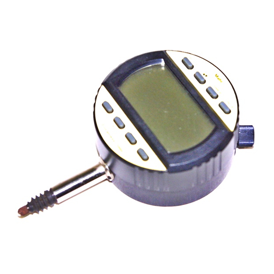
Bezeichnungen
1 Bedientasten
9 Gummibalg
2 Anzeige
10 Abdeckschraube
3 Einspannschaft
11 Ladenetzteil
4 Messbolzen
12 Einstellschlüssel für
5 Messeinsatz
Vorhub
6 Anschluss für
13 Vorhubeinstellschraube
Ladenetzteil
14 Befestigungsöse 1085 b
7 Datenausgang
(Best.-Nr. 4336310)
8 Drehbares Bedien- und
15 Adapterbüchse 940
Anzeigeteil
(Best.-Nr. 4310103)
2. Vorbereiten des induktiven Feinzeigers
2.1 Spannungsversorgung
Die Spannungsversorgung kann erfolgen über:
• Ladenetzteil (11) oder
• über integrierten NiMh-Akku.
Wichtig: Vor dem ersten Gebrauch den Akku ca.14 Std.
laden. Wird während des Ladevorgangs mit dem Gerät
gearbeitet, erhöht sich die Ladedauer von 14 auf 16 Std.
– Ladenetzteil (11) an das Wechselspannungsnetz
(230 /115 /100V) und das Kabel an die Buchse (6) an-
schließen.
Kapazitätsprüfung des Akkus
– ON-Taste lang drücken (Abb. 2.1a).
– ON-Taste erneut drücken und die Taste gedrückt halten.
Bei Vollausschlag der Skalenanzeige ist der Akku voll ge-
laden. Mit dem Messgerät kann nun ca. 40 Std. netzunab-
hängig gearbeitet werden (2.1b).
Hinweis: Kapazitätsprüfung ist im Betrieb jederzeit durch
langes Drücken der ON-Taste möglich. Anzeigewert zeigt
Akkuspannung in Volt.
2.2 Einstellen des drehbaren Anzeige- und Bedienteils
Gehäuseoberteil ist von -90° bis +180° drehbar.
Wichtig: Wird das Display über die Anschlagpunkte A gedreht
kann dies zur Beschädigung des Messgeräts führen.
2.3 Anbringen von Abhebeeinrichtungen
2.3a) Abhebung mit Drahtabheber (Zubehör 4346010)
– Abdeckschraube (10) mit Münze entfernen
– Handabhebung (2.3a) in das Gehäuse einschrauben
– Messbolzen in das Gehäuse eindrücken, bis ein deutliches
Klicken zu hören ist
– Ggf. Drahtabheber in die Handabhebung einschrauben.
– Ausbau erfolgt in umgekehrter Reihenfolge.
2.3b) Pneumatische Abhebung (Zubehör 4346011)
– Abdeckschraube (10) mit Münze entfernen
– Abhebung (2.3b) in das Gehäuse einschrauben
– Messbolzen in das Gehäuse eindrücken, bis ein deutliches
Klicken zu hören ist.
Für die Abhebung ist ein Überdruck von 5 bis 8 bar
erforderlich.
– Ausbau erfolgt in umgekehrter Reihenfolge.
2.4 Befestigung des Messgeräts
Hinweis:
Zur optimalen Nutzung des Messbereichs, Messgerät im ABS-
Modus (3.1c) betreiben und Einstellung möglichst nahe an
elektrischen Nullpunkt legen.
Messuhrhalterung
Zur Aufnahme wird eine mit einem Schlitz versehene Halter-
ung mit Aufnahmebohrung 8 H7 mm empfohlen (2.4a).
Hinweis: Ist eine Aufnahmebohrung mit 3/8" (9,52 mm)
vorhanden, muss die Adapterbüchse 940 (4310103) verwen-
det werden.
Wichtig! Schraube darf nicht auf den Einspannschaft drücken,
damit freier Lauf des Messbolzens gewährleistet ist.
Befestigungsöse 1085 b (Zubehör 4336310)
– Vier Schrauben der Geräterückwand lösen.
Span of error*
– Rückwand entfernen
– Befestigungsöse anbringen (2.4b).
mm (inch)
0.0006 (.00002")
2.5 Austausch des Messeinsatzes
0.0006 (.00002")
Falls Einsatz nicht von Hand lösbar,
0.0003 (.00001")
– Messbolzen mit Zange festhalten. Zum Schutz der Messbol-
zenoberfläche ein Stück Stoff benützen.
– Messeinsatz mit zweiter Zange entfernen.
upwards 2.4 mm
Wichtig! Nichtbeachtung kann zu Schäden im Geräteinneren
downwards 0.4 mm (adjustable)
oder am Messbolzen führen.
4.6 mm
0.7-0.9 N
2.6 Anbringen der Messkrafteinstellung
inductive
(Zubehör 4346012)
LCD, height of digits 6.5 mm
NiMh
– Abdeckschraube (10) mit Münze entfernen.
approx. 40 h
– Messkrafteinstellschraube in Gehäuse einschrauben bis
schwarzer Dichtring nicht mehr sichtbar ist (halbe Messkraft).
approx. 14 h
IP 54 acc. IEC 60529 when used
Durch weiteres Einschrauben wird die Messkraft erhöht.
with rubber bellows
2.7 Austausch der Messkraftfeder
+5° C to +40° C
–10° C to +60° C
– Abdeckschraube (10) mit Münze entfernen.
RS232C compatible via interface-
– Messkraftfeder entfernen und gegen gewählte ersetzen.
cable with opto-coupler,
Digimatic or USB
2.8 Einstellen des Vorhubs
185 g
4346000 (230 V), 4346900 (115 V),
– Vorhub ist mit Innensechskantschlüssel (12) im Bereich
4346901 (100 V)
-1,3 mm bis 0* einstellbar.
Hinweis: Einstellung des Vorhubs ist dann sinnvoll, wenn
ein Werkstück in eine Messvorrichtung eingeführt werden
soll, ohne den Messbolzen dabei manuell oder pneumatisch
abzuheben.
*bezogen auf elektrischen Nullpunkt
DE
Designations
34,5
8,5
1 Operating keys
6
10
7
2 Display
3 Mounting shank
1
8
4 Measuring spindle
5 Contact point
mm/inch
RANGE
ON/OFF
16,5
6 Socket for charger cable
7 Data exit
8 Swivelling operating and
0
30
30
0.00
I
mm
9 Rubber bellows
ABS
8,5
PRESET
ABS
0
RESET
14
2
SET
Extramess 2000
19
13
3
ø.375“
2. Preparing the Inductive Dial Indicator
15
ø8h6
2.1 Power supply
9
4 4
4
Power supply is either supplied by the:
ø4
• Mains powered charger (11) or
5
• Integrated NiMh-rechargeable battery.
12
Important: Prior to the first use the battery should be
11
2.1
charged for approx. 14 hours. Using the instrument during
charging increases the charging time from 14 to 16 h.
– Plug the mains powered charger (11) into your mains
(230 /115 /100 V) and the cable into the socket (6).
Checking the battery capacity
RANGE
ON/OFF
mm/inch
– Execute long activation of the ON-key to switch the on the
measuring instrument (2.1a).
– Activate the ON-key again and keep it depressed. A full
0
30
bar graph indicates a fully charged battery. 40 hours of
0.00
I
30
autonomous use of the instrument is now possible (2.1b).
mm
ABS
Note: Checking the battery capacity during operation is pos-
PRESET
ABS
0
RESET
sible by long activation of the ON-key. Value displayed is the
SET
Extramess 2000
battery voltage.
2.2 Setting of the swivelling operating and display unit
The display can be swivelled from -90° to +180°.
Important: Turning the display past the stops A can lead to
damage of the instrument.
2.1a)
2.1b)
2.3 Mounting of the lifting devices
mm/inch
RANGE
ON/OFF
mm/inch
RANGE
ON/OFF
2.3a) Manual lift with Cable release (Accessory 4346010)
– Remove the cover screw (10) by using a coin
– Screw the manual lift into the housing (2.3a)
0
0
– Push the measuring spindle into the housing until a definite
30
30
21
30
0.00I
klick can be heard.
– In the event of a cable release being used it is necessary
mm
ABS
BAT
to screw the same into the manual lift.
– Disassembly in reverse order.
PRESET
ABS
0
RESET
PRESET
ABS
0
RESET
SET
SET
2.3b) Pneumatic lift (Accessory 4346011)
2.2
0°
– Remove the cover screw (10) by using a coin
-90°
– screw the pneumatic lift into the housing (2.3b)
– Push the measuring spindle into the housing until a definite
mm/inch
RANGE
ON/OFF
klick can be heard.
For lift-off a pressure of 5 to 8 bar is required.
– Disassembly in reverse order.
0
30
0.00
I
30
A
mm
ABS
PRESET
ABS
0
RESET
SET
Extramess 2000
+180°
A
10
2.3
2.7
2.3 a
2.4 Mounting of the measuring instrument
Note: For optimum use of the measuring range adjust the
measuring instrument while in ABS-mode (3.1c) as close
as possible to the electrical zero position (the middle of the
measuring range).
mm/inch
RANGE
ON/OFF
Mounting device
0
For mounting we recommend a device with a split mounting
30
0.00
30
I
bore of dia. 8 H7 mm (2.4a).
mm
ABS
Note: Devices with a mounting bore of dia. 3/8" (9,52 mm)
PRESET
ABS
0
RESET
require an adapter bush 940 (4310103).
SET
Important! In order to ensure unrestricted movement of the
Extramess 2000
2.6
2.3 b
measuring spindle do not clamp the mounting shank directly
with a screw.
Mounting lug 1085 b (Accessory 4336310)
– Undo the screws on the rear of the housing
– Remove the cover lid
– Screw on the mounting lug (2.4b).
2.5. Exchange of the contact point
2.4
ø 8 H7
To unscrew a tight contact point please proceed as follows:
2.4a)
– Hold the spindle tight with a pair of pliers using a piece of
cloth to protect the measuring spindle from damage
– Use a second pair of pliers to unscrew the contact point.
Important! Ignoring this advice may lead to damage of the
interior of the instrument or of the measuring spindle.
2.6 Attaching the device for setting the measuring force
2.4b)
(Accessory 4346012)
– Using a coin undo the cover screw (10).
– Screw the measuring force setting screw into the hous-
ing until the black sealing ring is no longer visible (half of
measuring force). Turning the screw further increases the
measuring force.
2.7 Exchange of the measuring force spring
– Remove the cover screw (10) by using a coin
– Remove the measuring force spring and exchange it for
2.8
mm/inch
RANGE
ON/OFF
the spring providing the measuring force of your choice.
0
2.8. Setting of the preliminary stroke
30
0.00
30
I
mm
– The preliminary stroke is set with the hexagon wrench (12)
ABS
in the range of -1.3 mm to 0*.
PRESET
ABS
0
RESET
Note: This setting can be useful, if a workpiece is to be in-
SET
Extramess 2000
serted into a measuring device without manually or pneumati-
12
cally lifting up the measuring spindle.
* based on electrical zero point
EN
10 Cover screw
11 Mains powered
charger
12 Key for preliminary
stroke setting
13 Screw for preliminary
stroke setting
14 Mounting lug 1085 b
display unit
(Order no. 4336310)
15 Adapter bush 940
(Order no. 4310103)
8/29/2014 1:30:16 PM
Werbung

Verwandte Anleitungen für Mahr Extramess 2000


Inhaltszusammenfassung für Mahr Extramess 2000
- Seite 1 Für die Abhebung ist ein Überdruck von 5 bis 8 bar For lift-off a pressure of 5 to 8 bar is required. • After a long storage period (over 6 - 12 months) can dem 23. März 2006 durch Mahr in den Verkehr gebracht erforderlich. – Disassembly in reverse order.
- Seite 2 ON/OFF mm/inch RANGE ON/OFF => max. 5 Std. Arbeitszeit verbleiben => max. 5 h operating time remains Extramess 2000 4.2b) – BAT-Symbol blinkt 4.2b) – BAT-symbol flashes => Akku laden! => Charge battery! 4.2c) – BAT-Symbol und Charge an 4.2c) – BAT-symbol and Charge on =>...