453145 ISS Q 08.00 Inhalt: Schnittzeichnung, Seite 2-3 Warnungen, Seite 5 Einführung in das W+ Programm, Seite 6 1.1 Das W+ Programm, Seite 6 1.2 Die W-Pumpe, Standard- und Zusatzausstattungen, Seite 6 1.3 Identifizierung der Pumpenmodelle, Seite 6 1.4 Identifizierung der Motormodelle, Seite 6 Montage der Pumpe, Seite 7 2.1 Positionierung, Seite 7 2.2 Anpassung des Rohrsystems, Seite 7...
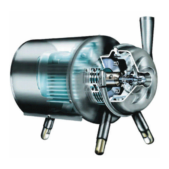
Warnungen Lesen Sie diese Anweisungen vollständig durch, bevor Sie die Pumpe aufstellen und in Betrieb nehmen. Wenden Sie sich an den nächsten APV-Händler, wenn Sie noch weitere Fragen haben. Prüfen Sie, daß die Spezifikationen des Motors und der Motorsteuerung zutreffen. Das gilt besonders für Einsatzbereiche, in denen Explosionsgefahr besteht.
Inducer - Wi+. Prüfen Sie das Typenschild der Pumpe und überzeugen Sie sich davon, daß es sich bei Ihrer Pumpe tatsächlich um eine der o.g. Ausgaben handelt. WHP+ und W+140/50 sind in einer gesonderten Anweisung beschrie- ben, die der Pumpe beigefügt ist. Die WK+ Pumpe (Ausführung mit Konsole) ist in einem ergänzenden Handbuch beschrieben.
381434 ISS S 01.98 381316 ISS Q 11.95 381325 ISS T 11.98 Montage der Pumpe Positionierung Die folgenden Punkte sind zu beachten: Die Pumpe ist so aufzustellen, daß das Saugrohr so kurz wie möglich und ein Gefälle zum Sauganschluß der Pumpe hin vorhanden ist. Halten Sie die Anzahl der Ventile, Krümmer und T -Stücke an der Saugseite der Pumpe so niedrig wie möglich.
381434 ISS S 01.98 381326 ISS Q 11.95 Vor der Inbetriebnahme Bevor Sie die Pumpe anlaufen lassen, ist das Saugrohr zu zerlegen und zu rei- nigen. Sämtliche Fremdkörper sind aus der Pumpe zu entfernen. Überprüfung des Pumpengehäuses auf Fremdkörper Zerlegen Sie die Pumpe wie im folgenden beschrieben: Unterbrechen Sie die Stromversorgung.
381434 ISS S 01.98 Instandhaltung Prüfung der Wellendichtung Prüfen Sie die Dichtheit der Wellendichtung der Pumpe regelmäßig. Bei Undichtigkeiten tauschen Sie die Wellendichtung bzw. ihre betreffenden Teile wie im folgenden beschrieben aus. Austausch der Wellendichtung In der großen Schnittzeichnung (Seite 2-3) sind die Lage und der Aufbau der Dichtung sowohl für Standarddichtungen als auch für Dichtungen mit Flüssigkeitsspülung/Dampfspülung dargestellt.
Seite 12
381434 ISS S 01.98 Instandhaltung Prüfen Sie auch den Leitring (Pos11) und den Laufring (Pos10) auf Anzeichen von Verschleiß. Die Verschleißflächen müssen vollkommen frei von Rissen sein. Sollte die nicht der Fall sein, ist sowohl der Leitring als auch der Laufring auszutausahen. 11.a Bei Wellendichtungen mit Flüssigkeitsspülung und bei aseptischen Wellendichtungen sind auch die hinteren Dichtungsringe (Pos15,16) auf Verschleiß...
381434 ISS S 01.98 381327 ISS Q 11.95 381328 ISS Q 11.95 381329 ISS Q 11.95 381331 ISS Q 11.95 Instandhaltung Austausch des Motors Abb. 9 Laufrad Der Standardmotor der W+ Pumpe ist mit einem vorderen Motorlager ausge- Pumpengehäuse stattet. Falls der Motor ausgetauscht werden muß, muß der Austauschmotor ebenfalls mit einem vorderen Lager ausgestattet sein.
381434 ISS S 01.98 381332 ISS Q 11.95 Instandhaltung Befestigen Sie den Plastikstern (pos 21) am Laufrad (pos 4). Pos 4 Pos 21 Montieren Sie das Pumpengehäuse (pos 1) mit dem Klemmring (pos 2). Pos 1 Schieben Sie die Welle (pos 6) so weit vor, bis das Laufrad (pos 4) mit dem Plastikstern (pos 21) in Berührung kommt.
Die angegebenen Werte gelten, wenn die Pumpen mit 2.900 U/min betrieben werden und der Motor mit einer Verkleidung abgedeckt ist. Die Werte für W+25/210 gelten, wenn die Pumpe mit 1.450 U/min betrieben wird. Falls die Pumpen mit 1.450 U/min betrieben werden, reduzieren sich die Werte um ca.
381434 ISS S 01.98 Technische Daten Anzugsdrehmomente für Laufräder und Wellen Für die in der Welle angebrachten Schrauben vorgeschriebenes Anzugsdrehmoment: M8: 30 Nm (22lbf ft) M10: 55Nm (40 lbf ft) Für die Hutmutter vorgeschriebenes Anzugsdrehmoment: M10: 45Nm (33 lbf ft) M14: 70Nm (52 lbf ft) M20: 200Nm...
Seite 19
Improving Process Profitability...Continuously Operating Manual 453145 ISS Q 08.00 W+ pump Process to Boardroom Automation...
Seite 21
Warnings, page 5 Introduction to the W+ programme, page 6 1.1 The W+ range, page 6 1.2 The W+pump, options and extras, page 6 1.3 Identifying the pump model, page 6 1.4 Identifying the motor model, page 6 Installing the pump, page 7 2.1 Positioning, page 7...
341609 ISS Q 11.95 381352 ISS T 02.98 381353 ISS S 05.96 Sectional Drawing Sections 1 Sections 2...
Seite 23
341609 ISS Q 11.95 Pump housing Clamp ring O-ring Impeller Cap nut Shaft Rear flange Extension frame Section 1 Standard seal Section 2 Seal with liquid/steam flushing Rotor ring Stator ring O-ring O-ring Seal cover Rotor ring Stator ring O-ring O-ring Drain pipe Seal cover...
- double O-ring sealing of pump body fitted for sterile flushing (Wa+) - heavy duty clamping ring, increasing the pump’s maximum per missible outlet pressure to 25 bar (available for W+30/120, W+55/35, W+55/60, W+60/110, W+70/40) or 20 bar (available for W+80/80).
381434 ISS S 01.98 381326 ISS Q 11.95 381325 ISS T 11.98 Installation of the pump 2.1 Positioning The pump must be positioned so that the suction pipe is as short as possible and there is a falling gradient towards the suction nozzle. Keep the number of valves, bends and tee-pieces on the suction side to an absolute minimum.
381434 ISS S 01.98 381326 ISS Q 11.95 Before start-up Before starting the pump, dismantle and clean the suction pipe. Any foreign material in the pump should be removed. 3.1 Checking the pump body for foreign material Remove the pump body as described below: Disconnect the power supply.
381434 ISS S 01.98 Maintenance 5.1 Checking the shaft seal Check the shaft seal in the pump for leaks on a regular basis. If the shaft seal is leaking, replace it or its relevant parts as described below. 5.2 Replacing the shaft seal The general drawing shows the position and structure of the shaft seal - both ordinary seals and seals with water/steam flushing.
Seite 30
381434 ISS S 01.98 Maintenance 11. Check the stator ring (pos 11) and rotor ring (pos 10) for signs of wear too. The wearing surfaces must be completely free of scratches/cracks. If not, the rotor ring and stator ring must both be replaced.
381434 ISS S 01.98 381327 ISS Q 11.95 381328 ISS Q 11.95 381329 ISS Q 11.95 381331 ISS Q 11.95 Maintenance Impeller Fig. 9 5.3 Replacement of motor Pump body The standard motor for the W+ pump has a front-mounted bearing. If the motor is replaced, the new motor must also have a front-mounted bearing.
381434 ISS S 01.98 381332 ISS Q 11.95 Maintenance 14. Fit the plastic star (pos 21) on the impeller (pos 4). Pos 4 Pos 21 15. Fit the pump body (pos 1) with the clamp ring (pos 2). Pos 1 16.
381434 ISS S 01.98 6.3 Tightening torque for impellers and shafts Tightening torque required for the screws in the shaft: M8: 30 Nm (22 lbf ft) M10: 55 Nm (40/ lbf ft)) Tightening torque required for the cap nut: M10: 45 Nm (33 lbf ft) M14: 70 Nm (52 lbf ft)
Improving Process Profitability...Continuously Spare part list 453145 ISS Q 08.00 Process to Boardroom Automation...
Seite 38
381333 ISS S 05.98 381334 ISS S 05.98 381335 ISS S 05.98 Pumpens mål / Pump dimensions TG.1 Motor 80-132M TG.2 Motor 160M-200L TG.3 Motor 225S-250M Nominal +2.5 Tolerances: D 1 , D 2 Z 90 + 5 mm Others + 2 mm Norminel Andre...
Seite 39
381354 ISS D 11.00 Pumpens mål / Pump dimensions W+10/8 W+22/20 W+30/80 W+25/210 W+35/35 W+35/55 W+30/120 W+50/8 W+55/35 W+55/60 W+60/110 W+65/350 W+70/40 W+80/80 W+110/130 NW100 63,5 NW100 101,6 NW150 63,5 101,6 63,5 101,6 NW150 63,5 101,6 80-132M Motor Tg 1...
Seite 40
381336 ISS Q 11.95 381337 ISS Q 11.95 Pumpens mål / Pump dimensions TG.1 Motor 80-132M type A TG.2 Motor 160M-250M type A TG.1-2 Med konsol type A With bracket type A Motor 80-250M 100L 112M 132S 132M 160M 160L 180M 180L 200L...
Seite 41
381338 ISS Q 11.95 381339 ISS Q 11.95 Pumpens mål / Pump dimensions TG.3 Motor 80-132M type B TG.4 Motor 160M-200L type B TG.3-4 Med konsol type B With bracket type B Motor 80-200L 100L 112M 132S 132M 160M 160L 180M 180L 200L...
381415 ISS B 11.00 Pumpe komplet / Pump complete Pumpe type / Pump type W+10/8 W+22/20 W+30/80 W+25/210 W+35/35 W+35/55 W+30/120 W+50/8 Stk/Qty Benævnelse Description Del nr. / Part No. 188710 168644 Pumpehus Pump housing 168838 182702 168696 182645 182703...
Seite 44
381416 ISS T 11.00 Løbehjul / Impeller Pumpe type / Pump type Løbehjul/ Impeller W+22/20 W+30/80 W+35/35 W+35/55 W+50/8 Del nr. / Part No. Ø200 267328 Ø195 273889 Ø190 273890 273891 Ø185 Ø180 253740 273892 267492 Ø175 253739 273893 267493 253738 Ø170...
Seite 45
381417 ISS T 11.00 Løbehjul / Impeller Pumpe type / Pump type Løbehjul/ W+10/8 W+30/120 W+55/35 W+55/60 W+60/110 W+70/40 W+80/80 W+110/130 W+25/210 W+65/350 Impeller Del nr. / Part No. Ø290 253748 253749 Ø285 267680 267700 267701 Ø280 267681 Ø275 267682 267702 Ø270...
Seite 46
381352 ISS T 02.98 381353 ISS S 09.96 Akseltætning / Shaft seal...
Seite 47
1xFixing kit (dobbelt / double) + 1xFace kit + 1xPos.10 Ombygning fra dobbelt til enkelt tætning / Rebuild from double to single seal: 1xFixing kit (enkelt / single) + 1xPos.13 * APV anbefaler at SiC/Kul benyttes som sekundær tætningsring APV recommend the use of SiC/Carbon as secondary seal...
Seite 48
381447 ISS U 11.00 Tætningssæt, standard / Seal kit, standard Pumpetype / Pump type W+10/8 W+22/20 W+30/80 W+25/210 W+35/35 W+35/55 W+30/120 W+50/8 Komplet Materiale Material Complete Del nr. / Part No. 1-2-3-4-5 EPDM - SiC/SiC EPDM - SiC/SiC 800875 800800...
Seite 50
381413 ISS E 11.00 Mellemflange - Afdækning / Extension frame - Shaft guard Pos 1 Mellemflange - Extension frame Motor Pumpetype 132* 200** 225*** Pos 1 Del nr / Part No. W+10/8 188735# 261566# 261566# W+22/20 261566# 261566# 261566# W+30/80 261565 261565...
Seite 51
381413 ISS E 11.00 Mellemflange - Afdækning / Extension frame - Shaft guard Pos 3 - Afdækning - Shaft guard Motor Stk. Pumpe type Pump type Del nr / Part No. W+10/8 800836 188334 188334 188334 188334 188334 W+22/20 188333...
Seite 52
381536 ISS U 11.00 Stativ / Frame for motor 80-132M Motor Centerhøjde Centreheight Stk/Qty Benævnelse Description Del nr. / Part No. Komplet - Complete - understøtning frame 801094 Stativ Frame 273965 Rørben 274385 Tå Ball type foot 800868 O-ring O-ring 724121 Skrue Screw...
Seite 53
381345 ISS S 11.00 Stativ / Frame for motor 80-132M Motor Centerhøjde / Centreheight Stk/Qty Benævnelse Description Del nr. / Part No. Komplet - Complete - understøtning frame 801095 801096 801097 801098 801099 Stativ Frame 188440 188441 188442 188443 188444 Rørben 194434 194434...
Seite 54
381346 ISS T 11.00 Stativ / Frame for motor 160M-250M Motor 160M - 160L 180M - 180L 200L Centerhøjde / Centreheight Stk/Qty Benævnelse Description Del nr. / Part No. Komplet - Complete - understøtning frame 801100 801101 801102 801103 801104 801105 801106 801107...
Seite 55
381347 ISS T 11.00 Stativ / Frame for motor 160M-250M Motor 225S - 225M 250M Centerhøjde / Centreheight Stk/Qty Benævnelse Description Del nr. / Part No. Komplet - Complete - understøtning frame 801108 801109 801110 Møtrik 772449 772449 772449 Rørben 268474 194461 194460...
Seite 56
381348 ISS T 11.00 Konsol / Bracket Motor TG.1 Med konsol type A With bracket type A Centerhøjde / Centreheight Motor 80-132 Stk/Qty Benævnelse Description Del nr. / Part No. Konsol Bracket 267735 267736 267737 267738 267739 Fladprofil, foran Fitting, front 268479 268479 268479...
Seite 57
381349 ISS S 11.00 Konsol / Bracket Motor TG.2 Med konsol type B With bracket type B Centerhøjde / Centreheight Motor 80-132 Stk/Qty Benævnelse Description Del nr. / Part No. Konsol Bracket 267740 267741 267742 267743 267744 Fladprofil, foran Fitting, front 268479 268479 268479...
Seite 58
381350 ISS T 11.00 381351 ISS S 11.00 Dæksel og kappe / Collar and shroud Motor W+10/8 Stk/Qty Benævnelse Description Del nr. / Part No. Kappe Shroud 188445 188445 188445 188446 188446 188447 Dæksel Collar 188809 194420 194421 194422 194423...
Seite 59
160-250 Erstatter Pos nr.1 side 56 i standard manualen for W+pumpen / Replace item No.1 at page 56 in the standard manual for W+pumps Erstatter Pos nr.7 side 49 i standard manualen for W+pumpen / Replace item No.7 at page 49 in the standard manual for W+pumps...
Seite 60
453164 ISS Q 11.00 Aseptisk centrifugalpumpe Wa+ / Aseptic centrifugal pump Wa+ Wa+ 10/8 Andre Wa+ pumper Wa+ 22/20 Stk/Qty Del nr./Part No. Benævnelse Description Vinkelforskruning 1/8” RG Union Elbow 1/8” RG 773094 Lige forskruning Straight union 773592 Union Elbow 1/8” RG 773094 Vinkelforskruning 1/8”...
Seite 61
3A og 3A-elpoleret pumpehus / 3A and 3A-electropolished pumphouse Pumpehuse med drænmuffe - 3A Pumphouses with drain socket - 3A Pumpehuse med drænmuffe - 3A Pumpetype / Pumptype Pumphouses with drain socket - 3A W+ 10/8 280393 280394 W+22/20 W+25/210 280395 W+30/80 280396 W+30/120 280397 280398 W+35/35...