Herunterladen Inhalt Inhalt Diese Seite drucken
Lenze E82ZAFAC010 Montageanleitung
Vorschau ausblenden Andere Handbücher für E82ZAFAC010:

Werbung

Verfügbare Sprachen

Verfügbare Sprachen

EDK82ZAFAC-010
.51(
APPLICATION-I/O PT
E82ZAFAC010
Funktionsmodul
Function module
Module de fonction
Montageanleitung
Mounting Instructions
Instructions de montage

Werbung

Inhaltsverzeichnis
loading

Inhaltszusammenfassung für Lenze E82ZAFAC010

  • Seite 1 EDK82ZAFAC-010 .51( Montageanleitung Mounting Instructions Instructions de montage APPLICATION-I/O PT E82ZAFAC010 Funktionsmodul Function module Module de fonction ...
  • Seite 2  Lesen Sie zuerst diese Anleitung und die Dokumentation zum Grundgerät, bevor Sie mit den Arbeiten beginnen! Beachten Sie die enthaltenen Sicherheitshinweise.  Please read these instructions and the documentation of the standard device before you start working! Observe the safety instructions given therein! ...
  • Seite 3 E82ZAFAC010 E82ZAFA017/E82ZAFX006...
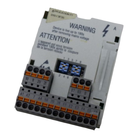
  • Seite 4  Digitale Ein- und Ausgänge, Steckerleiste X3.3  NR Typenschild  R 0Abb. 0Tab. 0  Tipp! Aktuelle Dokumentationen und Software-Updates zu Lenze Produkten finden Sie im Internet jeweils im Bereich ”Services & Downloads” unter http://www.Lenze.com  EDK82ZAFAC-010 DE/EN/FR 4.0...
  • Seite 5: Gültigkeit

    E82ZAF Gerätereihe APPLICATION-I/O Gerätegeneration Variante: PT-Ausführung Hardwarestand Softwarestand Bestellbezeichnung E82ZAFAC0103A30 Funktion Das Funktionsmodul ermöglicht das Ansteuern von Lenze Antriebsreglern 8200 vector mit analogen und digitalen Steuersignalen. Einsetzbarkeit Einsetzbare Grundgeräte Einsetzbar ab Grundgeräte-Version Frequenzumrichter 8200 vector Vx14  EDK82ZAFAC-010 DE/EN/FR 4.0...
  • Seite 6: Inhaltsverzeichnis

    ........Mit Lenze-Einstellung .
  • Seite 7: Sicherheitshinweise

    Sicherheitshinweise Definition der verwendeten Hinweise Sicherheitshinweise Definition der verwendeten Hinweise Um auf Gefahren und wichtige Informationen hinzuweisen, werden in dieser Dokumenta- tion folgende Piktogramme und Signalwörter verwendet: Sicherheitshinweise Aufbau der Sicherheitshinweise:  Gefahr! (kennzeichnet die Art und die Schwere der Gefahr) Hinweistext (beschreibt die Gefahr und gibt Hinweise, wie sie vermieden werden kann) Piktogramm und Signalwort...
  • Seite 8: Restgefahren

    Sicherheitshinweise Restgefahren Restgefahren  Gefahr! Beachten Sie die in den Anleitungen zum Grundgerät enthaltenen Sicherheitshinweise und Restgefahren.  EDK82ZAFAC-010 DE/EN/FR 4.0...
  • Seite 9: Lieferumfang

    Lieferumfang Lieferumfang   E82ZAFAC010   E82ZAFX007/010/011/012, E82ZAFA017 Pos. Lieferumfang siehe Funktionsmodul E82ZAFAC010 Montageanleitung Steckerleiste mit Federkraftanschluss, 4-polig  Steckerleiste mit Federkraftanschluss, 3-polig  14 Steckerleiste mit Federkraftanschluss, 13-polig  Befestigungsbügel Verwendung siehe  BA/MA 8200 vector  EDK82ZAFAC-010 DE/EN/FR 4.0...
  • Seite 10: Mechanische Installation

    Mechanische Installation Mechanische Installation Folgen Sie zur mechanischen Installation des Funktionsmoduls den Hinweisen in der Mon- tageanleitung des Grundgerätes. Die Montageanleitung des Grundgerätes ƒ ist Teil des Lieferumfangs und liegt jedem Gerät bei. ƒ gibt Hinweise, um Beschädigungen durch unsachgemäße Behandlung zu vermeiden. ƒ...
  • Seite 11: Elektrische Installation

    Elektrische Installation EMV-gerechte Verdrahtung Elektrische Installation EMV-gerechte Verdrahtung Für eine EMV-gerechte Verdrahtung beachten Sie folgende Punkte:  Hinweis! Steuerleitungen getrennt von Motorleitungen verlegen. ƒ Schirme so weit wie möglich an die Klemmen führen (ungeschirmte ƒ Aderlänge < 40 mm). Legen Sie die Schirme der Steuerleitungen bzw. Datenleitungen wie folgt ƒ...
  • Seite 12: Verdrahtung

    Elektrische Installation Verdrahtung Verdrahtung Daten der Anschlussklemmen Steckerleiste mit Federkraftanschluss Anschlussmöglichkeiten starr: 1,5 mm (AWG 16) flexibel: ohne Aderendhülse 1,5 mm (AWG 16) mit Aderendhülse, ohne Kunststoffhülse 1,5 mm (AWG 16) mit Aderendhülse, mit Kunststoffhülse 0,5 mm (AWG 20) Abisolierlänge 9 mm Umgang mit Steckerleisten ...
  • Seite 13 Elektrische Installation Versorgung der Reglersperre (CINH) über die interne Spannungsquelle (X3.3/20) 1U 9 +5 V X3.1 X3.2 1I 2U 62 63 1k … 10k AIN1 AIN2 AOUT1 AOUT2 +20 V X3.3 7 A4 20 28 E1 E2 E3 E4 E5 E6 DIGOUT1 DFOUT1 DIGOUT2...
  • Seite 14 Elektrische Installation X3.1/ Signaltyp Funktion Pegel (Lenze-Einstellung: Fettdruck) 1U/2U Analoge Ist- oder Sollwerteingänge (Leitspannung) 0 ... +5 V Eingänge Bereich umschalten mit Jumper und C0034 0 ... +10 V -10 V ... +10 V 1I/2I Ist- oder Sollwerteingänge (Leitstrom) 0 ... +20 mA Bereich umschalten mit Jumper und C0034 +4 ...
  • Seite 15 Elektrische Installation X3.3/ Signaltyp Funktion Pegel (Lenze-Einstellung: Fettdruck) Digitale Betriebsbereit Ausgänge 0/+20 V bei DC intern nicht vorkonfiguriert 0/+24 V bei DC extern GND, Bezugspotenzial Frequenz- Zwischenkreisspannung HIGH: ausgang +18 V ... +24 V (HTL) LOW: 0 V DC-Versorgung für X3/A1 und X3/A2 +20 V (intern, Brücke zu X3/20)
  • Seite 16: Inbetriebnahme

    Inbetriebnahme Vor dem ersten Einschalten Inbetriebnahme Vor dem ersten Einschalten  Hinweis! Wenn Sie die Inbetriebnahme mit einer von der Lenze-Einstellung ƒ abweichenden Konfiguration durchführen, lesen Sie die Anweisungen ”Individuelle Einstellungen”, siehe 19. Achten Sie darauf, ƒ – dass die Jumper nur in ausgeschaltetem Zustand gesteckt werden dürfen.
  • Seite 17: Jumperstellungen Für Eingänge

    Inbetriebnahme Jumperstellungen für Eingänge Jumperstellungen für Eingänge Lenze-Einstellung (siehe Fettdruck in Tabellen) N J P O J Q T J V U J NM  Hinweis! Wird ein Sollwertpotentiometer intern über X3.2/9 versorgt, unbedingt Jumper auf Spannungsbereich 0 ... +5 V einstellen. Andernfalls kann nicht der ganze Drehzahlbereich durchfahren werden.
  • Seite 18: Jumperstellungen Für Ausgänge

    Inbetriebnahme Jumperstellungen für Ausgänge Jumperstellungen für Ausgänge Lenze-Einstellung (siehe Fettdruck in Tabellen) N J P O J Q T J V U J NM Analoge Ausgänge Mögliche Pegel 0 ... +10 V 0 ... +20 mA +4 ... +20 mA X3.2/62...
  • Seite 19: Mit Lenze-Einstellung

    Inbetriebnahme Mit Lenze-Einstellung Mit Lenze-Einstellung Schritt Vorgehensweise Bemerkungen Netzspannung zuschalten. Der Antriebsregler ist nach ca. 1 Sekunde betriebsbereit. Die Reglersperre ist aktiv. Reaktion des Antriebsreglers Die grüne LED blinkt.  Keypad: (falls aufgesteckt) Digitale Eingänge ansteu- Lenze-Einstellung ern. Rechtslauf: – E1, E2, E3, E4: LOW Linkslauf: –...
  • Seite 20: Technische Daten

    Technische Daten Anschlussdaten Technische Daten Anschlussdaten X3.1/ 1U/2U Temperaturfehler (0...+60°C) für Pegel (bezogen auf Momentanwert): 1I/2I 0 ... +5 V: 0 ... +10 V: 0,6 % 0,6 % -10 ... +10 V: 0,6 % 0/+4 ... +20 mA: Linearitätsfehler: 0,5 % ±...
  • Seite 21: Einsatzbedingungen

    Technische Daten Einsatzbedingungen Einsatzbedingungen Umgebungsbedingungen Klimatische Bedingungen Lagerung 1 K3 nach IEC/EN 60721-3-1 - 25 ... + 60 °C Transport 2 K3 nach IEC/EN 60721-3-2 - 25 ... + 70 °C Betrieb 3 K3 nach IEC/EN 60721-3-3 - 20 ... + 60 °C Verschmutzungsgrad 2 nach IEC/EN 61800-5-1 Schutzart...
  • Seite 22: Abmessungen

    Technische Daten Abmessungen Abmessungen E82ZAFA018 alle Maße in mm  EDK82ZAFAC-010 DE/EN/FR 4.0...
  • Seite 23 Technische Daten Abmessungen  EDK82ZAFAC-010 DE/EN/FR 4.0...
  • Seite 24 Digital inputs and outputs, plug connector X3.3  35 Nameplate  25 0Fig. 0Tab. 0  Tip! Current documentation and software updates concerning Lenze products can be found on the Internet in the ”Services & Downloads” area under http://www.Lenze.com  EDK82ZAFAC-010 DE/EN/FR 4.0...
  • Seite 25 Variant: PT version Hardware version Software version Order designation E82ZAFAC0103A30 Function The function module enables the user to control Lenze 8200 vector controllers with analog and digital control signals. Application range Can be used with As of version Frequency inverter...
  • Seite 26 ......... Commissioning using Lenze settings .
  • Seite 27: Safety Instructions

    Safety instructions Definition of notes used Safety instructions Definition of notes used The following pictographs and signal words are used in this documentation to indicate dangers and important information: Safety instructions Structure of safety instructions:  Danger! (characterises the type and severity of danger) Note (describes the danger and gives information about how to prevent dangerous situations)
  • Seite 28: Residual Hazards

    Safety instructions Residual hazards Residual hazards  Danger! Observe the safety instructions and residual hazards included in the instructions for the standard device.  EDK82ZAFAC-010 DE/EN/FR 4.0...
  • Seite 29: Scope Of Supply

    Scope of supply   E82ZAFAC010   E82ZAFX007/010/011/012, E82ZAFA017 Pos. Scope of supply E82ZAFAC010 function module Mounting Instructions Plug connector with spring connection, 4-pole  Plug connector with spring connection, 3-pole  34 Plug connector with spring connection, 13-pole ...
  • Seite 30: Mechanical Installation

    Mechanical installation Mechanical installation Follow the notes given in the Mounting Instructions for the standard device for the mechanical installation of the function module. The Mounting Instructions for the standard device ƒ are part of the scope of supply and are enclosed with each device. ƒ...
  • Seite 31: Electrical Installation

    Electrical installation Wiring according to EMC Electrical installation Wiring according to EMC Please observe the following for wiring according to EMC guidelines:  Note! Separate control cables from motor cables. ƒ Lead the shields as far as possible to the terminals (unshielded core length ƒ...
  • Seite 32: Wiring

    Electrical installation Wiring Wiring Terminal data Plug connector with spring connection Possible connections rigid: 1.5 mm (AWG 16) flexible: without wire end ferrule 1.5 mm (AWG 16) with wire end ferrule, without plastic sleeve 1.5 mm (AWG 16) with wire end ferrule, with plastic sleeve 0.5 mm (AWG 20) Bare end...
  • Seite 33 Electrical installation Controller inhibit (CINH) supply via internal voltage source (X3.3/20) 1U 9 +5 V X3.1 X3.2 1I 2U 62 63 1k … 10k AIN1 AIN2 AOUT1 AOUT2 +20 V X3.3 7 A4 20 28 E1 E2 E3 E4 E5 E6 DIGOUT1 DFOUT1 DIGOUT2...
  • Seite 34 Electrical installation X3.1/ Signal type Function Level (Lenze setting: in bolt print) 1U/2U Analog Actual or setpoint inputs (master voltage) 0 ... +5 V inputs Use jumper and C0034 to change range 0 ... +10 V -10 V ... +10 V...
  • Seite 35 Electrical installation X3.3/ Signal type Function Level (Lenze setting: in bolt print) Digital Ready for operation outputs 0/+20 V at DC internal Not prefabricated 0/+24 V at DC external GND, reference potential Frequency DC-bus voltage HIGH: output +18 V ... +24 V (HTL)
  • Seite 36: Commissioning

    Commissioning Before switching on Commissioning Before switching on  Note! If your configuration differs from the Lenze settings, please read the ƒ instructions given under ”Individual settings”. 39 Please observe ƒ – that the jumpers can only be plugged when the device is switched off.
  • Seite 37: Jumper Positions For Inputs

    Commissioning Jumper positions for inputs Jumper positions for inputs Lenze setting (bold printing in tables) N J P O J Q T J V U J NM  Note! If a setpoint potentiometer is supplied internally via X3.2/9, the jumper must be set between 0 ...
  • Seite 38: Jumper Positions For Outputs

    Commissioning Jumper positions for outputs Jumper positions for outputs Lenze setting (bold printing in tables) N J P O J Q T J V U J NM Analog outputs Possible levels 0 ... +10 V 0 ... +20 mA +4 ... +20 mA X3.2/62...
  • Seite 39: Commissioning Using Lenze Settings

    Commissioning Commissioning using Lenze settings Commissioning using Lenze settings Step Procedure Comments Switch on the mains After approx. 1 second, the controller is ready for operation. voltage. Controller inhibit is active. Controller reaction The green LED is blinking.  Keypad: (if attached) Control digital inputs.
  • Seite 40: Technical Data

    Technical data Connection data Technical data Connection data X3.1/ 1U/2U Temperature error (0...+60°C) for level (ref. to current value): 1I/2I 0 ... +5 V: 0 ... +10 V: 0.6 % 0.6 % -10 ... +10 V: 0.6 % 0/+4 ... +20 mA: Linearity error: 0.5 % ±...
  • Seite 41: Operating Conditions

    Technical data Operating conditions Operating conditions Ambient conditions Climatic conditions Storage 1 K3 acc. to IEC/EN 60721-3-1 - 25 ... + 60 °C Transport 2 K3 acc. to IEC/EN 60721-3-2 - 25 ... + 70 °C Operation 3 K3 acc. to IEC/EN 60721-3-3 - 20 ...
  • Seite 42: Dimensions

    Technical data Dimensions Dimensions E82ZAFA018 All dimensions in mm  EDK82ZAFAC-010 DE/EN/FR 4.0...
  • Seite 43 Technical data Dimensions  EDK82ZAFAC-010 DE/EN/FR 4.0...
  • Seite 44 56 Plaque signalétique  45 0Fig. 0Tab. 0  Conseil ! Les mises à jour de logiciels et les documentations récentes relatives aux produits Lenze sont disponibles dans la zone ”Téléchargements” du site Internet : http://www.Lenze.com  EDK82ZAFAC-010 DE/EN/FR 4.0...
  • Seite 45 Validité Le présent document s’applique aux modules suivants : ƒ Modules de fonction E82ZAFAC010, E/S APPLICATION PT, à partir de la version 3A.30. Ce document est uniquement valable avec la documentation relative aux appareils de base compatibles. Identification ‚ƒ ...
  • Seite 46 ....... . . Avec réglage Lenze ..........
  • Seite 47: Consignes De Sécurité

    Consignes de sécurité Définition des conventions utilisées Consignes de sécurité Définition des conventions utilisées Pour indiquer des risques et des informations importantes, la présente documentation utilise les mots et symboles suivants : Consignes de sécurité Présentation des consignes de sécurité ...
  • Seite 48: Dangers Résiduels

    Consignes de sécurité Dangers résiduels Consignes d’utilisation Pictogramme et mot associé Explication  Remarque Remarque importante pour assurer un fonctionnement correct importante !  Conseil ! Conseil utile pour faciliter la mise en oeuvre  Référence à une autre documentation Dangers résiduels ...
  • Seite 49: Equipement Livré

    E82ZAFAC010   E82ZAFX007/010/011/012, E82ZAFA017 Pos. Equipement livré voir Module de fonction E82ZAFAC010 Instructions de montage Bornier à lame ressort, à 4 broches  Bornier à lame ressort, à 3 broches  55 Bornier à lame ressort, à 13 broches ...
  • Seite 50: Installation Mécanique

    Installation mécanique Installation mécanique Pour l’installation mécanique du module de fonction, suivre les consignes fournies dans les instructions de montage de l’appareil de base. Les instructions de montage de l’appareil de base ƒ font partie de la livraison standard et sont comprises dans l’emballage, ƒ...
  • Seite 51: Installation Électrique

    Installation électrique Câblage conforme CEM Installation électrique Câblage conforme CEM Pour réaliser un câblage conforme CEM, respectez les points suivants :  Remarque importante ! Poser les câbles de commande séparément des câbles moteur. ƒ Conduire le blindage aussi loin que possible vers les bornes (longueur de fil ƒ...
  • Seite 52: Câblage

    Installation électrique Câblage Câblage Spécifications des bornes de raccordement Bornier à lame ressort Raccordements possibles Rigide : 1,5 mm (AWG 16) Souple : sans embout 1,5 mm (AWG 16) avec embout, sans cosse en plastique 1,5 mm (AWG 16) avec embout et cosse en plastique 0,5 mm (AWG 20) Fil dénudé...
  • Seite 53 Installation électrique Câblage Comment utiliser les borniers enfichables  Stop ! Suivre les instructions suivantes afin de protéger les borniers enfichables et les contacts du variateur. N’enficher ou ne retirer les borniers que lorsque le variateur est hors ƒ tension ! Câbler les borniers avant de les enficher ! ƒ...
  • Seite 54 Installation électrique Alimentation ”Blocage variateur (CINH)” via tension interne (X3.3/20) 1U 9 +5 V X3.1 X3.2 1I 2U 62 63 1k … 10k AIN1 AIN2 AOUT1 AOUT2 +20 V X3.3 7 A4 20 28 E1 E2 E3 E4 E5 E6 DIGOUT1 DFOUT1 DIGOUT2...
  • Seite 55 Installation électrique X3.1/ Type de Fonction Niveau signal (réglage Lenze : en caractères gras) 1U/2U Entrées Entrées de valeur réelle ou de consigne 0 ... +5 V analogiques (tension maître) 0 ... +10 V Commuter la plage à l’aide des cavaliers et -10 V ...
  • Seite 56 Installation électrique X3.3/ Type de Fonction Niveau signal (réglage Lenze : en caractères gras) Sorties Opérationnel numériques 0/+20 V pour CC interne Non préconfiguré 0/+24 V pour CC externe GND, potentiel de référence Fréquence Tension du bus CC HIGH (HAUT) : de sortie +18 V ...
  • Seite 57: Mise En Service

     Remarque importante ! Si vous réalisez la mise en service à l’aide d’une configuration différente du ƒ réglage Lenze, reportez-vous aux instructions ”Réglages individuels” (voir 60 Veillez à ce que ƒ – les cavaliers ne puissent être insérés qu’à l’état hors tension.
  • Seite 58: Positions Des Cavaliers Pour Les Entrées

    Mise en service Positions des cavaliers pour les entrées Positions des cavaliers pour les entrées Réglage Lenze (en caractères gras dans les tableaux) N J P O J Q T J V U J NM  Remarque importante ! Si un potentiomètre de consigne est alimenté en interne via X3.2/9, réglez impérativement les cavaliers sur la plage de tension 0 ...
  • Seite 59: Positions Des Cavaliers Pour Les Sorties

    Mise en service Positions des cavaliers pour les sorties Positions des cavaliers pour les sorties Réglage Lenze (en caractères gras dans les tableaux) N J P O J Q T J V U J NM Sorties analogiques Niveaux possibles 0 ... +10 V 0 ...
  • Seite 60: Avec Réglage Lenze

    Activer les entrées numériques de sorte que le variateur puisse se mettre en marche après le déblocage du variateur via la borne. Définir la valeur de Avec le réglage Lenze consigne Valeur de consigne : 0 ... +10 V Réglage individuel...
  • Seite 61 Mise en service Avec réglage Lenze  Remarque importante ! Le variateur n’est opérationnel que lorsque le niveau HIGH (HAUT) est ƒ présent au niveau de X3.3/28 (déblocage du variateur via la borne). – Veillez à ce que le blocage variateur puisse être défini par le biais de plusieurs sources.
  • Seite 62: Spécifications Techniques

    Spécifications techniques Données de raccordement Spécifications techniques Données de raccordement X3.1/ 1U/2U Erreur de température (0...+60°C) pour le niveau (sur la base de la valeur actuelle) : 1I/2I 0 ... +5 V : 0 ... +10 V : 0,6 % 0,6 % -10 ...
  • Seite 63: Conditions D'utilisation

    Spécifications techniques Conditions d’utilisation Conditions d’utilisation Conditions ambiantes Conditions climatiques Stockage 1 K3 selon CEI/EN 60721-3-1 - 25 ... + 60 °C Transport 2 K3 selon CEI/EN 60721-3-2 - 25 ... + 70 °C Fonctionnement 3 K3 selon CEI/EN 60721-3-3 - 20 ...
  • Seite 64: Encombrements

    Spécifications techniques Encombrements Encombrements E82ZAFA018 Toutes les cotes en mm  EDK82ZAFAC-010 DE/EN/FR 4.0...
  • Seite 65 Spécifications techniques Encombrements  EDK82ZAFAC-010 DE/EN/FR 4.0...
  • Seite 66  Lenze Drive Systems GmbH EDK82ZAFAC-010 Hans-Lenze-Straße 1 DE/EN/FR 4.0 D-31855 Aerzen © 06/2007 Germany TD06 +49 (0) 51 54 82-0 Service 00 80 00 24 4 68 77 (24 h helpline) Service +49 (0) 51 54 82-1112 E-Mail Lenze@Lenze.de Internet www.Lenze.com...

Diese Anleitung auch für:

Application-i/o pt

Inhaltsverzeichnis