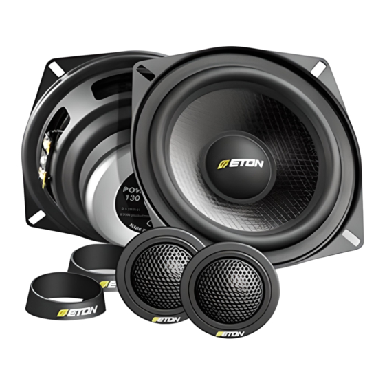
Inhaltszusammenfassung für Eton PRO 100 X
- Seite 1 GERMAN HIGH TECHNOLOGY PRO 100 X PRO 100 X 2-WEGE SYSTEM / 2-WAY SYSTEM PRO 130 X PRO 130 X 2-WEGE SYSTEM / 2-WAY SYSTEM PRO 160 X PRO 160 X 2-WEGE SYSTEM / 2-WAY SYSTEM EINBAU /BEDIENUNG INSTALLATION / OPERATION...
- Seite 2 Hearing Damage Continuous, excessive exposure to sound pressure levels in excess of 85 dB can cause a loss of hearing. ETON components are capable of producing sound pressure levels greater than 85 dB. Volume and Driver Awareness...
-
Seite 3: Montage
MONTAGE Nehmen Sie Ihr Fahrzeug nicht in Betrieb, bevor alle Komponenten des Lautsprechersystems fest und sicher eingebaut sind. Lose Teile können im Falle eines plötzlichen Bremsmanövers oder eines Unfalls zu gefährlichen, fliegenden Geschossen werden. Bohren oder schrauben Sie nicht in eine Fahrzeugverkleidung oder einen teppichbezogenen Boden, bevor Sie sich versichert haben daß... - Seite 4 Befestigungsteile, die bei der De- montage beschädigt werden können. Die Besonderheit des ETON Einbaugehäuses ist, daß Sie den Hoch- tönereinsatz schwenken und drehen können, um die optimale Ab- strahlrichtung zu Ihrer Sitzposition zu erzielen. Siehe Abbilung 3.
-
Seite 5: Elektrischer Anschluss
ELEKTRISCHER ANSCHLUSS Achten Sie immer darauf, wenn Sie Kabel durch ein Blech verlegen, daß das Kabel durch eine Kunststoffdurchführung geschützt ist und nicht von einer scharfen Blechkante beschädigt werden kann, um Kurzschlüsse und daraus resultierende Schäden am Verstärker oder der Lautsprecher zu vermeiden. Bitte verwenden Sie nur die beigefügten Krempkontakte für die An- schlüsse und löten Sie diese nicht an, um eine Beschädigung der Komponenten zu vermeiden. -
Seite 6: Mechanical Installation
MECHANICAL INSTALLATION Do not use your automobile until all components of the loudspeaker system have been secured to the interior framework. Failure to do so may turn a component into a dangerous, flying projectile during a sudden stop or accident. Do not drill or drive screws through any vehicle interior or carpeted floor before inspecting the underside for potential punctures to control lines or cables. - Seite 7 The specialty of the ETON mounting cabinet is that the tweeter ele- ment can be turned and swiveled to achieve the optimum hearing path to your sitting position. See figure 3.
-
Seite 8: Electrical Installation
ELECTRICAL INSTALLATION Whenever you run wires through sheet metal, use tape or grommets to properly insulate the metal edges from cable jackets. This technique prevents chafing and possible short circuits that could damage an amplifier or the loudspeakers. Please use only the enclosed crimp-type terminals when connecting and do not solder them to avoid possible damage to the compo- nents. - Seite 9 Ring und Gitter (Zubehör - nicht enthalten) Ring and grille (optional - not included) Blechmutter Tinnerman Nut Blechschraube Self-Threading Screw PRO 100 X/130 X Ring und Gitter (Zubehör - nicht enthalten) Ring and grille (optional - not included) Blechmutter Tinnerman Nut Blechschraube...
- Seite 10 Abbildung 2 Einbau Hochtöner Figure 2 Flush mount of Tweeter ø 40,0 mm Cable: + red black...
- Seite 11 Abbildung 3 Einbau Hochtöner Flush mount of Tweeter Figure 3 Schwenken und Drehen Demontage: Swivel and turn Disassembly: Lautsprecher in mittlerer Position ! Speaker in middle position ! Abbildung 4 Aufbau Hochtöner Figure 4 Surface mount of Tweeter Cable: + red black...
- Seite 12 Abbildung 5 Anschlußplan für Weiche Figure 5 Wiring diagram crossover Zum Autoradio (Verstärker) schwarz / weiss + schwarz - To the automobile radio (Amplifier) black / white + black - Zum Hochtöner Zum Mittel/Tieftöner schwarz / rot + schwarz / weiss + schwarz - schwarz - To the Tweeter...
- Seite 13 Abbildung 6 Anschlußplan für Wiring diagram for Figure 6 2 Kanal 2-channel 4 Kanal 4-channel AUTORADIO / SOURCE UNIT VERSTÄRKER AMPLIFIER TWEETER TWEETER WEICHE WEICHE CROSSOVER CROSSOVER MID/WOOFER MID/WOOFER TWEETER TWEETER WEICHE WEICHE CROSSOVER CROSSOVER MID/WOOFER MID/WOOFER...
-
Seite 14: Technische Daten / Specifications
Technische Daten / Specifications PRO 100 X 2-Wege System / 2-Way Component System Nennbelastbarbeit / Nominal Power 60 W 90 W Max. Belastbarkeit / Max. Power Konus / Cone Material Paper coated Impedanz / Nominal Impedance Frequenzbereich / Frequency Response...


