Fujitsu D3128 Handbuch
Mainboard
Vorschau ausblenden
Andere Handbücher für D3128:
- Handbuch (63 Seiten) ,
- Technische beschreibung (80 Seiten)
Inhaltsverzeichnis
Verfügbare Sprachen
Verfügbare Sprachen
Kapitel
Inhaltsverzeichnis

Verwandte Anleitungen für Fujitsu D3128


Inhaltszusammenfassung für Fujitsu D3128
-
Seite 7: Inhaltsverzeichnis
Mainboard D3128 Deutsch - Inhalt Übersicht über das Mainboard D3128 ....................2 Mainboard D3128..........................4 Handbuchkonventionen........................4 Wichtige Hinweise ..........................5 Allgemeine Informationen im Zusammenhang mit Boards............5 Hardware-Spezifikationen ........................7 Blockdiagramm............................. 9 Systemsicherheitsfunktionen......................10 Grundlegende Sicherheitsfunktionen ..................10 Trusted Platform Module (TPM) ....................10 SmartCase DynamicUSB ...................... -
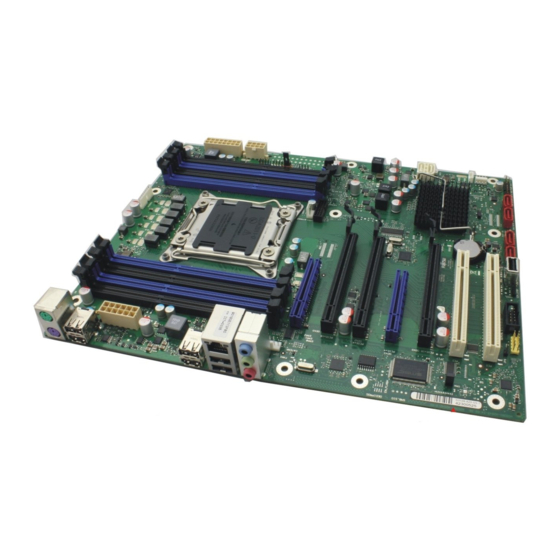
Seite 8: Übersicht Über Das Mainboard D3128
Deutsch Mainboard D3128 2 – Übersicht über das Mainboard D3128 PC 2009 FAN 4 PWR12V_2 LGA 2011 INTR FAN 1 USB 3 FP PCIe x4 Gen 3 PCIe x16 Gen 3 PCIe x4 Gen 2 PCIe x4 Gen 3 SATA... - Seite 9 Mainboard D3128 Deutsch - Risk of Explosion if battery is replaced by an incorrect type. Dispose of used batteries according to the instructions. Il y a risque d’explosion si la batterie est remplacée par une batterie de type incorrect. Mettre au rebut les batteries usagées conformément aux instructions.
-
Seite 10: Mainboard D3128
4 – Mainboard D3128 Basierend auf dem Intel® C600 Chipsatz zeichnet sich das D3128 durch eine Reihe hochmoderner Technologien aus. Dazu zählen: Support für die Intel Xeon® Prozessor-Serien bis zu 8 Kernen (Cores) im LGA 2011 Sockel, multiple PCI-Express Busse, Quad Channel DDR3 Speicherdesign, Onboard PCI-Express Gigabit Ethernet, SATA-Ports und multiple USB 2.0 / 3.0- (Universal Serial... -
Seite 11: Wichtige Hinweise
Mainboard D3128 Deutsch - Wichtige Hinweise Zum Zugriff auf das installierte Mainboard muss das System geöffnet werden. Wie das System auseinandergebaut und wieder zusammengesetzt wird, ist im begleitenden Bedienerhandbuch beschrieben. Zur Vermeidung von Interferenzen müssen die Verbindungskabel für die Peripherie entsprechend abgeschirmt sein. - Seite 12 Deutsch Mainboard D3128 6 – Boards mit elektrostatisch empfindlichen Geräten (Electrostatic Sensitive Devices (ESD)) sind durch ein Etikett entsprechend gekennzeichnet. Bitte beachten Sie beim Umgang mit Boards, auf denen sich solche ESDs befinden, unbedingt Folgendes: ● Vor der Arbeit müssen Sie immer für eine statische Entladung (z. B. durch Berühren eines geerdeten Objekts) sorgen.
-
Seite 13: Hardware-Spezifikationen
Mainboard D3128 Deutsch - Hardware-Spezifikationen CPU – LGA2011 Sockel LAN – 10/100/1000 Ethernet Controller ● Bis zu zwei CPU-Sockel ● WakeOnLAN durch interessante Pakete und Magic-Packet™ ● Intel® Xeon Prozessoren im LGA2011- Paket ● PXE-Support ● Intel® QuickPath Architektur zwischen ●... - Seite 14 Deutsch Mainboard D3128 8 – Audio Erweiterte Systemüberwachung und - verwaltung ● Conexant CX20642 “Carson” ● Fujitsu Technolgy Solutions System ● Host-basiertes Audio mit 2-Kanal HD Management Audio ● Fujitsu Technolgy Solutions Thermal ● Stereokopfhörerausgang (ca. 50 mW bei Management 32 Ω)
-
Seite 15: Blockdiagramm
Mainboard D3128 Deutsch - Blockdiagramm CPU0 Memory Bus 4 channels Socket R 4x2 DDR3 Sandybridge 1333/1600 40xPCIe Gen3 SMBus PCIE x4 PCIE x8 Slot PCIE x16 PCIE x16 Slot PCIE x4 PCIE x 8 S lot PCIE x16 PCIE x16 Slot... -
Seite 16: Systemsicherheitsfunktionen
Deutsch Mainboard D3128 10 – Systemsicherheitsfunktionen Grundlegende Sicherheitsfunktionen Eine vollständige Beschreibung der grundlegenden Sicherheitsfunktionen ist in der BIOS- Spezifikation zu finden. Trusted Platform Module (TPM) Bei Trusted Platform Modules handelt es sich um eine Sicherheitslösung der Trusted Computing Group (TCG) zur Steigerung der Systemsicherheit. Das TPM befindet sich auf dem Motherboard und nutzt zur Kommunikation mit dem Rest der Plattform den LPC-Bus. -
Seite 17: Smartcase Dynamicusb
Mainboard D3128 Deutsch - SmartCase DynamicUSB Dies ist ein Hardware-Sicherheitsschaltkreis, durch den der USB-Port beim Entfernen eines USB- Geräts deaktiviert wird, so dass keine anderen USB-Geräte angeschlossen werden können. Auf diese Weise wird der Datendiebstahl durch Anschließen etwa eines USB-Sticks verhindert. Diese Funktion wird komplett über Hardware und BIOS realisiert. - Seite 18 Deutsch Mainboard D3128 12 – Folgende Geräteklassen werden innerhalb der USB-Spezifikation angegeben: Fett/kursiv dargestellte Klassen sind keine zulässigen USB-Geräte (wenn die Option SmartCase DynamicUSB aktiviert ist) – Ports, an denen während der BIOS-Phase solche Geräte angeschlossen sind, werden durch das BIOS deaktiviert.
-
Seite 19: Auswahl Der Korrekten Teile Für Das System
Vor der Installation dieses Motherboards in ein System müssen Sie sicherstellen, dass die maßgeblichen Systemteile folgenden Basisrichtlinien und -anforderungen entsprechen: Betrachtungen zur CPU (Central Processor Unit) ● Einzelprozessorsystem Das D3128 unterstützt Intel® Xeon® Prozessoren bis zu 8 Kernen (Cores) in einem LGA2011 Sockel. Systemspeicherschnittstelle ● Technologie Ungepufferte Single-Rank oder Dual-Rank DDR3 800/1066/1333/1600-DIMM-Module mit oder ohne ECC. -
Seite 20: Bios Post-Codes (Port 80-Statusanzeigen)
Deutsch Mainboard D3128 14 – BIOS POST-Codes (Port 80-Statusanzeigen) BIOS-POST-Codes werden auf dem LCD-Display (angeschlossen an den LCD-Anschluss) angezeigt. Kontrollpunktbereiche Bereich der Beschreibung Statuscodes 0x01 – 0x0B SEC-Ausführung 0x0C – 0x0F SEC-Fehler 0x10 – 0x2F PEI-Ausführung bis und inklusive Speichererkennung 0x30 –... - Seite 21 Mainboard D3128 Deutsch - 0x0A OEM-Initialisierung nach dem Laden des Microcodes 0x0B Cache-Initialisierung SEC-Fehlercodes 0x0C – 0x0D Reserviert für zukünftige AMI-SEC-Fehlercodes 0x0E Microcode nicht gefunden 0x0F Microcode nicht geladen SEC-Beep-Codes Keine SEC-Phase Statuscode Beschreibung Progress-Codes 0x10 PEI-Core wurde gestartet 0x11...
- Seite 22 Deutsch Mainboard D3128 16 – 0x35 CPU-Post-Memory-Initialisierung. Auswahl des Boot-Strap-Prozessors (BSP) selection 0x36 CPU-Post-Memory-Initialisierung. Initialisierung des System-Management- Modus (SMM) 0x37 Post-Memory-North-Bridge-Initialisierung wurde gestartet 0x38 Post-Memory-North-Bridge-Initialisierung (North-Bridge-Modul-spezifisch) 0x39 Post-Memory-North-Bridge-Initialisierung (North-Bridge-Modul-spezifisch) 0x3A Post-Memory-North-Bridge-Initialisierung (North-Bridge-Modul-spezifisch) 0x3B Post-Memory-South-Bridge-Initialisierung wurde gestartet 0x3C Post-Memory-South-Bridge-Initialisierung (South-Bridge-Modul-spezifisch) 0x3D...
- Seite 23 Mainboard D3128 Deutsch - S3 Resume-Fehlercodes 0xE8 S3 Resume fehlgeschlagen 0xE9 S3 Resume PPI nicht gefunden 0xEA Fehler S3 Resume Boot Script 0xEB Fehler S3 OS Wake 0xEC-0xEF Reserviert für zukünftige AMI-Fehlercodes Recovery-Progress-Codes 0xF0 Wiederherstellbedingung von Firmware ausgelöst (Auto recovery) 0xF1 Wiederherstellbedingung vom Anwender ausgelöst (Forced recovery)
- Seite 24 Deutsch Mainboard D3128 18 – DXE-Phase Statuscode Beschreibung 0x60 DXE Core wurde gestartet 0x61 NVRAM-Initialisierung 0x62 Installation der South Bridge Runtime Services 0x63 CPU-DXE-Initialisierung wurde gestartet 0x64 CPU-DXE-Initialisierung (CPU-Modul-spezifisch) 0x65 CPU-DXE-Initialisierung (CPU-Modul-spezifisch) 0x66 CPU-DXE-Initialisierung (CPU-Modul-spezifisch) 0x67 CPU-DXE-Initialisierung (CPU-Modul-spezifisch) 0x68 PCI-Host-Bridge-Initialisierung...
- Seite 25 Mainboard D3128 Deutsch - 0x96 PCI Bus Assign Resources 0x97 Console Output Devices Connect 0x98 Console Input Devices Connect 0x99 Super-IO-Initialisierung 0x9A USB-Initialisierung wurde gestartet 0x9B USB Reset 0x9C USB Detect 0x9D USB Enable 0x9E – 0x9F Reserviert für zukünftige AMI-Fehlercodes...
- Seite 26 Deutsch Mainboard D3128 20 – DXE-Fehlercodes 0xD0 CPU-Initialisierungsfehler 0xD1 North-Bridge-Initialisierungsfehler 0xD2 South-Bridge-Initialisierungsfehler 0xD3 Einige Architekturprotokolle sind nicht verfügbar 0xD4 Fehler bei der PCI-Resource-Zuordnung. Keine verfügbaren Resourcen 0xD5 Kein Speicherplatz für Legacy Option ROM 0xD6 Console Output Devices nicht gefunden 0xD7...
-
Seite 27: Für Oem Reservierte Kontrollpunktbereiche
0x3F – 0x4E OEM-PEI-Post-Memory-Initialisierungscodes 0x80 – 0x8F OEM-DXE-Initialisierungscodes 0xC0 – 0xCF OEM-BDS-Initialisierungscodes Betrachtungen zur Stromversorgung Netzstecker Das D3128 wird mit einem 12 V Netzteil oder einem ATX-Netzteil betrieben. 12 V-Netzteil 16-poliger Basis-Board-Netzstecker 12-poliger CPU-Netzstecker ATX-Netzteil Zusätzlicher 4-poliger Basis-Board- 24-poliger Basis-Board-Netzstecker Netzstecker... -
Seite 28: Installation Des Boards
Pin4: Fan PWM Dieser 4-polige Lüfteranschluss unterstützt die Geschwindigkeitsüberwachung Auf dem D3128 sind vier 4-polige Lüfteranschlüsse implementiert. Über diese Anschlüsse können Lüfter zur Kühlung von Gehäuse und Prozessor mit dem Motherboard verbunden werden. Kühlende Lüfter tragen zur Systemstabilität und -zuverlässigkeit während der Lebensdauer des Produkts bei. -
Seite 29: Frontblendenanschluss (Intern)
In der Regel verfügt ein Gehäuse über einige Kontroll- oder Signalkabel, die an ein Motherboard für die Festplatten-LED, Netz-LED, den Betriebsschalter und die Reset-Taste angeschlossen werden können. Für solche Zwecke wurde der Frontblendenanschluss auf dem D3128 implementiert. Signal Signal HD-LED +... - Seite 30 Deutsch Mainboard D3128 24 – USB 2.0-Port (intern) Signal Pin 1 VCC AUX (abgesichert) Data negative Data positive USB 3.0-Port (intern) – Intern/Vorderseite Signal Signal Pin 1 Pin 19 VBus USB 3.0 Port 2 RX Neg VBus USB 3.0 Port 2 RX Pos USB 3.0 Port 1 RX Neg...
-
Seite 31: Anschlüsse Für Systemüberwachung Und -Verwaltung
Mainboard D3128 Deutsch - Anschlüsse für Systemüberwachung und -verwaltung SCSI LED-Anschluss (Intern) POL Signal Pin 1 Nicht angeschlossen SCSI-ON LED (niedrig eingestellter Input) SCSI-ON LED (niedrig eingestellter Input) Nicht angeschlossen Konfigurations-Jumper innerhalb der Frontblende Standard-Jumper-Position (Password Skip (Kennwortüberspringung) und Recovery BIOS... -
Seite 32: Com1 Ports
Deutsch Mainboard D3128 26 – COM1 Ports PIN Signal PIN Signal Pin 1 Pin 2 DCD 1 DSR 1 SIN 1 RTS 1 SOUT 1 CTS 1 DTR 1 RI 1 TPM-Jumper Signal RST_PCI_TPM_L TPM_RESET_L Standardmäßig ist der TPM-Jumper gesetzt. Das Entfernen des Jumpers führt zur Deaktivierung der TPM-Funktionalität. -
Seite 33: Speicherinstallation
Speicherinstallation Vor der Installation muss sichergestellt werden, dass der einzusetzende Speicher kompatibel mit dem Motherboard und dem Prozessor ist. Das D3128-Board unterstützt bis zu sechs 240-polige, 1,5 V, 800/1066/1333/1600 MHz DDR3-Module. Hier einige Kernpunkte, die Sie vor der Speicherinstallation auf dem D3128 beachten müssen:... -
Seite 34: Vorgehen Bei Der Speicherinstallation
Deutsch Mainboard D3128 28 – Vorgehen bei der Speicherinstallation Bei der Installation von Speichermodulen müssen Sie darauf achten, dass die Module korrekt am Speichersockel ausgerichtet sind. Auf den Speichermodulen sollten sich kleine Kerben befinden, die zu den Kerben im Speichersockel passen. DDR-Module verfügen nur über eine Kerbe, die sich unmittelbar neben dem Mittelpunkt des Moduls/Sockels befindet. - Seite 35 Mainboard D3128 Deutsch - Entfernen eines Speichermoduls ► Die Klammern rechts und links am Speichersteckplatz nach außen drücken (1). ► Das Speichermodul aus dem Speichersteckplatz (2) ziehen. Mitunter kann schwierig sein, ein Modul in die korrekte Position zu bringen. Dies ist jedoch nur äußerst selten der Fall.
-
Seite 36: Installation Von Prozessor Und Kühlkörper
Installation von Prozessor und Kühlkörper Prozessorinstallation Der Prozessorsockel ist zum Schutz der Federkontakte mit einer Schutzkappe versehen. In einem Garantiefall kann das Mainboard von Fujitsu Technology Solutions nur mit angebrachter Schutzkappe zurückgenommen werden! Niemals die Unterseite des Prozessors berühren. Selbst kleinste Verschmutzungen durch Hautfette können den Prozessorbetrieb beeinträchtigen oder zur Zerstörung des... - Seite 37 Mainboard D3128 Deutsch - Den neuen Prozessor zwischen Daumen und Zeigefinger halten und in den Sockel (b) einsetzen, so dass die Markierung auf dem Prozessor mit der Markierung auf dem Sockel (b) abschließt. ► Den Rahmen nach unten klappen (1).
-
Seite 38: Montage Des Kühlkörpers
Deutsch Mainboard D3128 32 – Montage des Kühlkörpers Verwenden Sie nur den zum Lieferumfang zählenden Kühlkörper! Sorgen Sie dafür, dass zwischen Prozessor und Kühlkörper wärmeleitendes Material verwendet wird. Wenn am Kühlkörper bereits ein wärmeleitendes Polster (gummiartige Folie) angebracht ist, nutzen Sie dieses. Andernfalls muss eine sehr dünne Schicht wärmeleitender Paste aufgetragen werden. -
Seite 39: Installation Von Add-In-Karten
Mainboard D3128 Deutsch - Installation von Add-In-Karten Prüfen Sie vor der Installation von Add-In-Karten, ob diese vollständig kompatibel mit dem Motherboard sind. PCIe x4 Gen 3 PCIe x16 Gen 3 PCIe x4 Gen 2 PCIe x4 Gen 3 PCIe x16 Gen 3... -
Seite 40: Anschließen Von Externen Geräten
Deutsch Mainboard D3128 34 – Anschließen von externen Geräten Das Anschließen von externen Geräten an das Motherboard ist eine einfache Aufgabe. Zu den Standardkomponenten, die üblicherweise an das Motherboard angeschlossen werden, zählen Tastatur-, Maus- und Druckerkabel. In nachstehendem Diagramm wird der ATX-Port-Stack für... -
Seite 41: Austauschen Der Lithium-Batterie
Mainboard D3128 Deutsch - Austauschen der Lithium-Batterie Die installierte Lithium-Batterie versorgt den CMOS-Speicher mit Strom, damit die Systeminformationen permanent gespeichert bleiben. Wenn die Batterie leer oder fast leer ist, wird dem Benutzer eine entsprechende Fehlermeldung angezeigt. Die Lithium-Batterie muss dann ausgetauscht werden. -
Seite 42: Bios-Update
36 – BIOS-Update Wann sollte ein BIOS-Update durchgeführt werden? Fujitsu Technology Solutions stellt neue BIOS-Versionen zur Verfügung, um die Kompatibilität zu neuen Betriebssystemen, zu neuer Software oder zu neuer Hardware zu gewährleisten. Außerdem können neue BIOS-Funktionen integriert werden. Ein BIOS-Update sollte auch immer dann durchgeführt werden, wenn ein Problem besteht, das sich durch neue Treiber oder neue Software nicht beheben lässt.