ROBBE S 130 Handbuch
Quicklinks
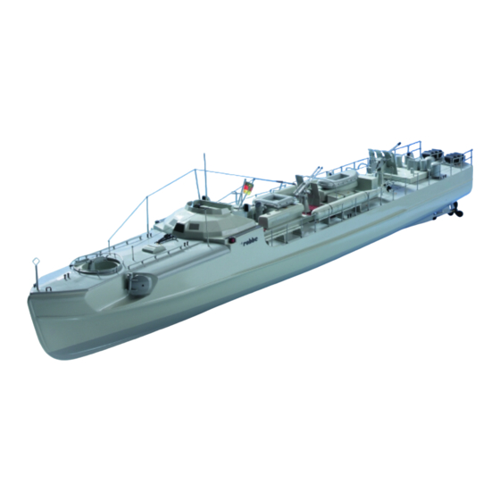
Technische Daten
Länge:
Breite:
Höhe:
Verdrängung:
Maßstab
Nicht enthaltenes, jedoch erforderliches Zubehör sowie
Klebstoffe siehe Beilageblatt.
Werkzeuge und Hilfsmittel siehe robbe Hauptkatalog
Allgemeine Hinweise für den Bauablauf
Die Numerierung entspricht im Wesentlichen der Reihenfol-
ge des Bauablaufs, wobei die Nummer vor dem Punkt die
Baustufe, die Nummer hinter dem Punkt das entsprechende
Bauteil angibt.
Verschaffen Sie sich bitte vor Baubeginn mit den Abbildun-
gen und den Anleitungstexten sowie den Stücklisten einen
Überblick über die einzelnen Bauschritte.
In Klammern gesetzte Nummern geben die Position des
Teils an.
In der Mitte dieser Anleitung finden Sie Fotoblätter und
Zeichnungen zum Heraustrennen. Auf die einzelnen Fotos
und Zeichnungen wird im Text hingewiesen (F = Foto oder
Zeichnung). Eine Übersichtszeichnung ist daher nicht erfor-
derlich.
Reste, die bei der Bearbeitung der Tiefziehteile wegge-
schnitten werden, sind auf den Teilen durch Schraffur ge-
kennzeichnet.
Nach Beschneiden der Tiefziehteile die Schnittkanten mit
Schleifpapier glätten.
Alle Klebestellen an den Kunststoffteilen sowie an Metall-
teilen vor dem Auftrag des Klebstoffs mit Schleifpapier
aufrauhen.
Die Kunststoffteile dürfen nur mit einem Kleber auf
Polyesterbasis z. Bsp. Stabilit-Expreß oder Sekundenkleber
geklebt werden.
Keine Kleber auf Epoxy-Basis verwenden.
Das Auffinden der Stanzteile erleichtert die Identifikations-
zeichnung auf Seite F2 . Die Stanzteile entsprechend nume-
Bauanleitung, Assembly instructions, Notice de montage
Specification
ca. 870 mm
Length:
Beam:
ca. 140 mm
Height:
ca. 180 mm
Displacement:
ca. 1650 g
Scale:
1:40
Please see separate sheet for details of adhesives and
other essential items not included in the kit.
Refer to the main robbe catalogue for more information
on tools and aids to building.
Sequence of assembly
In general terms the numbering of the parts corresponds to
the sequence of assembly; the number before the point
indicates the Stage of construction, the number after the
point the individual component.
Please study the plan, the instructions and the parts list so
that you have a clear idea how the model goes together
before you start construction.
Part Numbers in brackets give the position of the part.
In the centre of these instructions you will find sheets of
photographs and drawings. Please separate these sheets
and refer to the pictures when mentioned in the instructions
(F = photograph or drawing). That's why you don' need a
plan.
The vacuum-moulded parts include waste material which
has to be cut away before fitting. The unwanted areas are
shown hatched-in on the parts themselves.
After cutting the vacuum-moulded parts clean up the cut
edges with glasspaper.
Roughen up all joint areas of plastic and metal parts with
glasspaper before applying glue.
The plastic parts should be glued using polyester-based
resin glue, e.g. Stabilit Express, or cyano-acrylate („cyano").
Do not used epoxy resins on this model.
The identification drawing on page F2 of these instructions is
designed to help you locate and identify the die-cut parts.
Write the part numbers on the parts themselves, and drill
holes at the marked points using the sizes of drill stated on
Schnellboot - S 130
approx. 870 mm
approx. 140 mm
approx. 180 mm
approx. 1650 g
1:40
3
Caractéristiques techniques
longueur hors tout:
largeur hors tout:
hauteur:
poussée:
échelle:
Accessoires non contenus dans la boîte de construction
mais indispensables au montage, tels que la colle, cf.
feuillet joint.
Outillage et accessoires de montage, cf. catalogue
général robbe
Recommandations générales concernant la marche à
suivre pour le montage
La numérotation des pièces correspond en règle générale à
leur ordre d'intervention dans le montage, le numéro se
trouvant devant le point représente le stade de montage
alors que le numéro après le point désigne la pièce elle-
même.
Les numéros entre paranthèses montrent la position de la
pèce.
Avant d'entreprendre le montage du modèle, lire
attentivement la notice en liaison avec le plan et les listes de
pièces afin de vous faire une idée d'ensemble de la
construction et des diverses étapes de montage.
Au centre de la notice sont agrafés des feuillets de photos et
des croquis à détacher. Le texte fait référence aux photos (F
= photo ou croquis). C'est pourqui vous n'avez pas besoin
d'un plan.
Les chutes qui doivent être retirées d'éléments emboutis
sont représentées sur les schémas ou les pièces elles-
mêmes par des hachures.
Après voir découpé les pièces embouties, en poncer les
arêtes.
Avant d'appliquer la colle sur les pièces en plastique ou en
métal, poncer les surfaces d'encollage.
Les pièces en plastique ne doivent être collées qu'avec un
produit à base de polyester ou de la colle Stabilit-Express ou
cyanoacrylate.
Ne pas utiliser de colle à base époxyde.
L'identification des éléments estampés est facilitée par le
No.
1165
approx. 870 mm
approx. 140 mm
approx. 180 mm
approx. 1650 g
40e

Verwandte Anleitungen für ROBBE S 130


Inhaltszusammenfassung für ROBBE S 130
- Seite 1 Klebstoffe siehe Beilageblatt. feuillet joint. Refer to the main robbe catalogue for more information Werkzeuge und Hilfsmittel siehe robbe Hauptkatalog Outillage et accessoires de montage, cf. catalogue on tools and aids to building.
- Seite 2 Bauanleitung, Assembly instructions, Notice de montage Schnellboot - S 130 1165 rieren, nach Durchmesserangaben bohren und erst aus- the plan. Don’t separate any part until you actually need it; schéma de la page F2. Numéroter les pièces estampées, les trennen, wenn sie benötigt werden.
- Seite 3 Bauanleitung, Assembly instructions, Notice de montage Schnellboot - S 130 1165 À vous de déterminer le moment à choisir pour la mise en In general terms it is up to you to pick the optimum time for Zur Lackierung werden nur Lacke auf Acryl- oder Kunstharz- painting the model’s components, but the instructions inform...
- Seite 4 Bauanleitung, Assembly instructions, Notice de montage Schnellboot - S 130 1165 Der Bau des Modells Building the model La construction du modèle Stage 0, the boatstand, parts 0.1 - 0.4 Baustufe 0, der Bootsständer, Teile 0.1 - 0.4 Stade de montage 0, Berceau, pièces 0.1 à 0.4 °...
- Seite 5 Bauanleitung, Assembly instructions, Notice de montage Schnellboot - S 130 1165 - Die Löcher für die Stevenrohre und die Ruderkoker mit 4 motor torque. de coupe au papier de verre. L’arrière tableau est construit mm bohren. - Drill 4 mm Ø holes for the stern tubes and the rudder de manière asymétrique ce qui est voulu pour assurer une...
- Seite 6 Bauanleitung, Assembly instructions, Notice de montage Schnellboot - S 130 1165 - Stellringe 1.13 mit Madenschrauben 1.14 auf die Wellen collets on the shafts. - Glisser les arbres latéraux 1.12 (215 mm) en conséquence schieben. - Press the bushes 1.16 into the stern tubes 1.15 and fit them à...
- Seite 7 Bauanleitung, Assembly instructions, Notice de montage Schnellboot - S 130 1165 2.15 O - Ring, ø 3 x ø 5 2.14 Washer, 3.2 Ø 2.15 joint torique, ø 3 x ø 5 2.16 Servohebel 1 n.e. 2.15 O-ring, 3 Ø x 5 Ø...
- Seite 8 Bauanleitung, Assembly instructions, Notice de montage Schnellboot - S 130 1165 2.19 mit Madenschraube 2.20 aufschieben. - Visser la platine percée de servo 2.21 avec les vis - Connect the 40 mm long pre-formed pushrod 2.18 to the - Die gebohrte Servoplatte 2.21 mit Blechschrauben 2.22 autotaraudeuses 2.22 aux baguettes socle 2.23.
- Seite 9 Bauanleitung, Assembly instructions, Notice de montage Schnellboot - S 130 1165 - Hinweis: Das V-Kabel 3.7 wird nur zum Zusammen- using the double-sided foam tape 3.6. It is important that - Réaliser ensuite la câblage (schéma électrique „A“ ou „B“).
- Seite 10 Bauanleitung, Assembly instructions, Notice de montage Schnellboot - S 130 1165 - Raccorder le variateur 3.5 au cordon Y et observer les - Den Regler 3.5 am V-Kabel anschließen und Drehrichtung - Checking the speed controller system, version „B“ der Seitenmaschinen festlegen.
- Seite 11 Bauanleitung, Assembly instructions, Notice de montage Schnellboot - S 130 1165 - Die mittleren Teile der Scheuerleiste 4.1 aus dem L-Profil 4.12 Lateral girder, 110 wide 1 A, die-cut 4.15 écrou à riveter, M 2,5 nach Zeichnung anfertigen. Links und rechts beachten.
- Seite 12 Bauanleitung, Assembly instructions, Notice de montage Schnellboot - S 130 1165 - Löcher für die Einnietmuttern 4.15 und 4.16 bohren und - Glue the lateral girders 4.10 - 4.13 to the underside of the - Percer les trous pour les écrous à riveter 4.15 et 4.16 et les von oben ansenken.
- Seite 13 Bauanleitung, Assembly instructions, Notice de montage Schnellboot - S 130 1165 Rohrkörper, ø 15 x 80 Platform base, 12 x 15 2 A, die-cut montant, 12 x 15 2 A, est. Step, 6 x 7 1 B, die-cut marche, 6 x7 1 B, est.
- Seite 14 Bauanleitung, Assembly instructions, Notice de montage Schnellboot - S 130 1165 derkante des Decks fixieren. Die Seitenwände mit carefully and fix it to the front edge of the deck with clamps linge. Maintenir les parois latérales en position en Klebebandstreifen auf Position halten. Die schmalen Rän- appliquant des morceaux de ruban adhésif.
- Seite 15 Bauanleitung, Assembly instructions, Notice de montage Schnellboot - S 130 1165 - Die Fertigung der Brunnenreling wird auf einem Hilfs- - Drill all the holes in the forecastle deck as shown in the de construction. Détacher le schéma à l’échelle 1 et le brettchen vorgenommen.
- Seite 16 Bauanleitung, Assembly instructions, Notice de montage Schnellboot - S 130 1165 - Réaliser maintenant la mise en peinture de la coque et des stern to produce the waterline. - Die Lackierung von Rumpf und noch unlackierten Decks- éléments du pont non encore peints.
- Seite 17 Bauanleitung, Assembly instructions, Notice de montage Schnellboot - S 130 1165 7.19 Kompaß 1 Spzt 7.15 Stop sleeve, 1.5 Ø x 2 (manchon de laiton) 7.20 Fuß, ø 9 x 16 1 Ku-Rohr (Brass sleeve) 7.16 hampe de pavillon, ø 1,5 x 80 7.21...
- Seite 18 Bauanleitung, Assembly instructions, Notice de montage Schnellboot - S 130 1165 - Den Kompaß 7.19 mit dem Fuß 7.20 verkleben. - Drill holes for the formed wire parts in the bridge - Percer les trous appropriés pour les éléments de fil cintré...
- Seite 19 Bauanleitung, Assembly instructions, Notice de montage Schnellboot - S 130 1165 durch Platte und Decksrahmen bohren. and drill them 1 mm Ø through the plate and the deck - Découper la plaque d’écoutille 8.1 et détacher l’ouverture. frame. - Ajuster la plaque à la découpe du couvercle.
- Seite 20 Bauanleitung, Assembly instructions, Notice de montage Schnellboot - S 130 1165 glue it to the grating. The screw serves to centre the ger Dämpfung drehen läßt. Schraube mit Loctite sichern. - Munir le socle du palier et de la vis 8.13 et coller sur le support on the plinth.
- Seite 21 Bauanleitung, Assembly instructions, Notice de montage Schnellboot - S 130 1165 several coats to the end-grain faces. deckel 9.5, 9.6, die Schranktüren 9.7 und den Lukendeckel pont 9.1 et 9.2 et l’armoire à munitions 9.3 et l’écoutille 9.4 - Sand the blocks smooth using fine glasspaper. Glue the 9.8 aufkleben und bohren.
- Seite 22 Bauanleitung, Assembly instructions, Notice de montage Schnellboot - S 130 1165 10.21 Release bar, 1 Ø x 40 4 Brass rod - Den Achteraufbau 10.1 austrennen und anpassen. 10.20 support, 2 x 2 x 20 10.22 Smoke canister 4 Inj.
- Seite 23 Bauanleitung, Assembly instructions, Notice de montage Schnellboot - S 130 1165 - Fertige Nebelkannen auf das Deck kleben. - Glue the ramps to the hatch only. - Glisser les supports 10.20 par-dessous de telle sorte qu’il - Füße mit ø 1 mm durchbohren und Nägel 10.23 einsetzen.
- Seite 24 Bauanleitung, Assembly instructions, Notice de montage Schnellboot - S 130 1165 - Place the 4 cm AA gun in the cradle and insert the main - Schutzschild 11.9 bohren und abkanten. - Couder le dispositif de visée 11.6 d’un côté, le glisser dans shaft 11.8.
- Seite 25 Bauanleitung, Assembly instructions, Notice de montage Schnellboot - S 130 1165 auf die Achse 12.4 schieben und diese in eine Torpedo- - Trim the shells 12.1 to fit together neatly, and remove all - Ajuster les demi-coquilles 12.1 l'une sur l'autre et les rough edges.
- Seite 26 Bauanleitung, Assembly instructions, Notice de montage Schnellboot - S 130 1165 13.6 Split pin, 1.5 Ø x 1.5 x 25 13.7 axe, ø 1 x 7 1 fil de laiton 13.10 Stutzen 2 Spzt 13.7 Shaft, 1 Ø x 7 1 Brass rod 13.8...
- Seite 27 Bauanleitung, Assembly instructions, Notice de montage Schnellboot - S 130 1165 of spare cable to form the damper 13.8. Drill out the central 13.6 in das Dämpfungsteil schieben. la goupille 13.6 dans l’élément d’amortissement. hole in the well floor to accept the plastic sleeve, and glue it in the hole.
- Seite 28 Bauanleitung, Assembly instructions, Notice de montage Schnellboot - S 130 1165 verlöten. Um das Löten zu erleichtern, kann die Schraube binocular sights. Push the screw into a jig plate to make the in ein Hilfsbrettchen gesteckt werden. soldering easier to perform.
- Seite 29 In diesem Fall sofort ans Ufer fahren. - At the end of each run open the boat and leave it to dry out. robbe Modellsport GmbH & Co. KG Disconnect the battery from the speed controller, and only - Nach Beendigung des Fahrbetriebs das Boot öffnen und then switch off the transmitter.
- Seite 30 Fotos Photographies Photos Schnellboot S 130 1165 12.6 Identifikationszeichnung - Stanzteile Identification drawing for die-cut parts Fig. d'identification des pièces estampées...
- Seite 31 Fotos Photographies Photos Schnellboot S 130 1165 Bst. = Baustufe, stage, stade F = Foto oder Zeichnung, photograph or drawing, photo ou croquis ø 4 mm „ST ø 4 mm Bst 0, F 1 Bst 1, F 2 Bst 1, F 3 ø...
- Seite 32 Fotos Photographies Photos Schnellboot S 130 1165 2.13 M 1:1 1.19 1.19 2.7, 2.8 Bst 2, F 10 Bst 2, F 11 Bst 2, F 12 M 1:1 M 1:1 2.12 2.14 M 1:1 2.15 2.10 2.1, 2.2 2.14 2.3, 2.4 „FL“...
- Seite 33 Fotos Photographies Photos Schnellboot S 130 1165 Schaltplan „A“ Schaltplan „B“ Wiring diagram „A“ Wiring diagram „B“ Schéma électrique „A“ Schéma électrique „B“ 3.12 3.11 3.11 3.8, 3.9 3.8, 3.9 3.10 3.10 3.12 3.12 3.13 3.13 2.17 2.17...
- Seite 34 Fotos Photographies Photos Schnellboot S 130 1165 „A“ „B“ 3.4, 3.6 3.4, 3.6 3.5, 3.6 Bst 3, F 19 Bst 3, F 21 Bst 3, F 20 „R“ Bst 4, F 22 Bst 4, F 23 Bst 4, F 24...
- Seite 35 Fotos Photographies Photos Schnellboot S 130 1165 4.13 4.12 „D“ 4.11 10.1 4.10 „D“ Bst 4, F 25 Bst 4, F 26 Bst 4, F 27 „D“ (4.15) (8.1) (10.14) (4.16) Bst 4, F 28 4.14 4.15 4.12 4.16 „ST“...
- Seite 36 Fotos Photographies Photos Schnellboot S 130 1165 „KR“ Bst 5, F 33 Bst 5, F 32 Bst 5, F 34 Bst 5, F 36 Bst 5, F 37 Bst 5, F 35 5.14, M 1:1 28 mm 5.10 5.12 5.9-5.14 (13.9-13.11)
- Seite 37 Fotos Photographies Photos Schnellboot S 130 1165 Bst 6, F 41 Bst 6, F 44 Bst 6, F 42 Bst 6, F 43 6.4, 1 x 6.4, 1 x 6.4, 2 x Bst 6, F 45 Bst 6, F 46...
- Seite 38 Fotos Photographies Photos Schnellboot S 130 1165 6.7, 6.8 6.11 6.10 6.8-6.10 Bst 6, F 49 Bst 6, F 47 Bst 6, F 48 Bst 6, F 49 Bst 7, F 50 Bst 7, F 51 7.12 M 1:1 7.12 7.21...
- Seite 39 Fotos Photographies Photos Schnellboot S 130 1165 M 1:1 F 12...
- Seite 40 Fotos Photographies Photos Schnellboot S 130 1165 M 1:1 12.8 12.6 12.5 12.5 12.7 (6.7) F 13...
- Seite 41 Fotos Photographies Photos Schnellboot S 130 1165 M 1:1 M 1:1 M 1:1 7.14 4 x 7.13 7.18 7.16 7.17 7.15 Bst 7, F 54 Bst 7, F 55 7.7-7.9 2 x 8.2 7.27 7.28 7.8, 7.10-7.11 7.24 7.13 7.16-7.18 7.28...
- Seite 42 Fotos Photographies Photos Schnellboot S 130 1165 8.20 8.20 8.16 8.17 8.20 8.18 8.12 8.16 (8.13) 8.14 8.15 M 1:1 8.10 8.15 8.12 8.14 8.17 8.11 (8.9) 8.19 8.19 Bst 8, F 65 M 1:1 8.9-8.20 8.9-8.20 8.22 8.23 8.21...
- Seite 43 Fotos Photographies Photos Schnellboot S 130 1165 9.2, 9.6 (9.10) 9.2, 9.6 9.12-9.14 9.1, 9.5 9.1, 9.5 9.3, 9.7 9.12 9.3, 9.7 9.4, 9.8 9.1, 9.5 9.1, 9.5 9.4, 9.8 9.2, 9.6 9.2, 9.6 Bst. 9, F 69 Bst. 9, F 70 9.12-9.14...
- Seite 44 Fotos Photographies Photos Schnellboot S 130 1165 10.17 10.6 10.12 10.15 10.1 10.18 10.4 10.11 4.16 10.10 10.5 10.19 „HM“ 10.4 10.13 M 1:1 10.20 10.16 10.17 Bst. 10, F 77 Bst. 10, F 76 Bst. 10, F 78 10.15, 10.16 10.17...
- Seite 45 Fotos Photographies Photos Schnellboot S 130 1165 11.15 (11.6) 11.7 (11.8) 11.4 (11.5) M 1:1 11.3 11.14 11.2 11.9 11.5 11.6 11.1 (11.16) 11.15 11.6 11.11 11.10 (11.12) 11.5 + 11.13 11.14 11.11 11.12 Bst. 11, F 85 F 19...
- Seite 46 Fotos Photographies Photos Schnellboot S 130 1165 11.5 11.15 11.14 11.12 11.6 11.11 11.7 11.15 Bst. 11, F 87 Bst. 11, F 86 Bst. 11, F 88 12.1 12.7 12.2 12.4 12.1 12.5 12.6 12.7 12.8 12.3 Bst. 12, F 89 Bst.
- Seite 47 Fotos Photographies Photos Schnellboot S 130 1165 M 1:1 13.18 13.17 6.12 13.10 13.12 13.30 13.20 13.11 13.19 13.17 13.9 13.19 13.25 13.22 Bst. 13, F 97 Bst. 13, F 98 Bst. 13, F 99 13.12 13.16 13.9-13.11 13.30 13.14, 13.15 13.1...
- Seite 48 Fotos Photographies Photos Schnellboot S 130 1165 13.35 13.23 13.21 13.22 13.32 13.24 13.23, 13.24 13.33 13.31 Bst. 13, F 101 Bst. 13, F 102 Bst. 13, F 103 13.26 13.26 13.28 13.27 13.29 13.28 13.29 13.29 13.29 13.16 Bst. 13, F 104...