
Verwandte Anleitungen für Metek ServoTube 38


Inhaltszusammenfassung für Metek ServoTube 38
- Seite 1 ServoTube 38 Type/Typ XTA 3804 XTB 3804 XTA 3806 XTB 3806 XTA 3808 XTB 3808 Instruction Manual XTA 3810 XTB 3810 ServoTube 38 Publication Ref: UM03013/D Betriebsanleitung ServoTube 38 Publikation Ref: UM03013/D...
-
Seite 2: Inhaltsverzeichnis
1 Content 1 Inhalt 2 About this document 2 Über dieses Dokument 3 General description 3 Allgemeine Beschreibung 3.1 ServoTube 38 Actuator 3.1 ServoTube 38 Aktuator 3.2 ServoTube 38 3.2 ServoTube 38 3.3 Standards and Guidelines 3.3 Normen und Richtlinien... -
Seite 3: About This Document
Die vorliegende Betriebsanleitung stellt Ihnen den ServoTube 38 Actuator and provide you with informa- ServoTube 38 Aktuator vor und informiert Sie über alle tion on all the stages required for the installation of the Schritte zur Installation des Antriebs und zur Durch- drive and the performance of functional tests. -
Seite 4: General Description
3 General description 3.1 ServoTube 38 Aktuator 3.1 ServoTube 38 Actuator Der ServoTube 38 Aktuator ist eine optimale Lösung The ServoTube Actuator is an optimal solution for in- für die industrielle Positionieranwendung. Schneller dustrial position control. Faster than a ballscrew with... -
Seite 5: Servotube
3.2. ServoTube 38 3.2 ServoTube 38 ServoTube 38 delivers the speed of a belt-drive system ServoTube 38 liefert die Geschwindigkeit eines Rie- with the clean reliability of a linear motor at a price menantriebsystems mit der sauberen Zuverlässigkeit unprecedented in the industry. Familiar form factor, eines Linearmotors zu einem Preis, der beispiellos für... -
Seite 6: Standards And Guidelines
3.3 Standards and Guidelines 3.3 Normen und Richtlinien EU guidelines: the EU guidelines formulate the mini- EG-Richtlinien: Die EG-Richtlinien formulieren die mum requirements made on a product and must be ob- Mindestanforderungen an ein Produkt und müssen von served by all manufacturers and dealers marketing the allen Herstellern und Händlern beachtet werden, die product in the member states of the European Union. -
Seite 7: Safety Instructions
4 Safety instructions 4 Sicherheitshinweise Vor der Inbetriebnahme sind unbe- Before commissioning, it is dingt die Sicherheitshinweise zu lesen essential that the safety instructions und zu beachten! Eine Nichtbeach- in the relevant section are read, tung kann zu Gefahren bei Personen understood and then observed! WARNING WARNUNG... -
Seite 8: Warning Symbols And Meanings
4.1 Warning Symbols and Meanings 4.1 Warnsymbole und Bedeutungen In this User Manual warning symbols are used. These In der vorliegenden Betriebsanleitung werden die un- are intended to alert you to the potential hazards to ten aufgelisteten Warnsignale verwendet. Bitte lesen personnel which are associated with the equipment und befolgen Sie diese sorgfältig. - Seite 9 4.1 Warning symbols and meanings 4.1 Warnsymbole und Bedeutungen EMC precautions: This equipment is intended for EMC Sicherheitsvorkehrungen: Das Gerät ist für use in a light industrial environment. It is recommended eine Verwendung in einer Leichtindustrieumgebung that the following precautions be observed during vorgesehen.
-
Seite 10: Technical Data
5.Technical Data 5. Technische Daten 5.1 Electrical specification 5.1 Motorspezifikationen 3804 3806 3808 3810 FORCER TYPE/Primäreinheit units/ Einheiten S (1) P (1) S (1) P (1) S (1) P (1) S (1) P (1) Peak force @ 25 C ambient for 1 sec / 1116 1488 1860... -
Seite 11: Xta Force/Velocity Profiles
5.2 XTA FORCE /VELOCITY PROFILES 5.2 XTA KRAFT/GESCHWINDIGKEITSPROFILE (WITH AN OPERATING VOLTAGE OF 325 VD.C.) (MIT EINER BETRIEBSSPANNUNG VON 325 VD.C.) S=series forcer phases S=Seriale Phasen der Primäreinheit P=parallel forcer phases P=Parallele Phasen der Primäreinheit XTA3804S force/velocity XTA3804P force/velocity PEAK PEAK CONTINUOUS CONTINUOUS... - Seite 12 5.2 XTB FORCE /VELOCITY PROFILES 5.2 XTB KRAFT/GESCHWINDIGKEITSPROFILE (WITH AN OPERATING VOLTAGE OF 325 VD.C.) (MIT EINER BETRIEBSSPANNUNG VON 325 VD.C.) S=series forcer phases S=Seriale Phasen der Primäreinhei P=parallel forcer phases P=Parallele Phasen der Primäreinheit XTB3804S force/velocity XTB3804P force/velocity PEAK PEAK CONTINUOUS CONTINUOUS...
-
Seite 13: Thermal Specifications
5.3 Thermal Specifications/ Thermische Daten 3804 3806 3808 3810 units/ FORCER TYPE/ PRIMÄREINHEIT Einheiten Maximum phase temperature/ Max. Phasentemperatur Thermal resistance R / Thermischer 0.23 0.16 0.13 0.11 thphase-housing Widerstand Rth Phase-Gehäuse With 25 x 25 x 2.5 cm heatsink plate/ Mit 25 x 25 x 2,5 cm Kühlkörperplatte Power dissipation @ 25 C ambient/ 89.3... -
Seite 14: Position Sensor
5.5 Position Sensor 5.5 Positionsgeber The position sensor outputs analogue, differential sine Als Positionsrückmeldung gibt der Lagegeber analoge and cosine signals for providing position feedback. Signale, Sinus und Cosinus Differenzsignale aus. Un- Figure C.1 shows the relationships between forcer ten dargestellt ist das Verhältnis zwischen der Gegen- phase back EMF and position sensor outputs for one EMK und der Sensorsignale der Primäreinheit für eine direction of motion (as shown by arrows in Figures C.1... -
Seite 15: Forcer Over Temperature Sensor
VALUE UNITS SPECIFICATION WERT EINHEITEN ANGABE Output signal period 71.2 Ausgangssignal-Periode 71.2 Signal amplitude (between +/- signal) Signal Amplitude (zw. +/- Signal) pk-pk pk-pk Output current ±10 Ausgangsstrom ±10 Versorgungsspannung 5 ± 0.25 V d.c. Supply voltage 5 ± 0.25 V d.c. -
Seite 16: Cable
Value Units Wert Einheiten SPECIFICATION ANGABE Resistance in the temperature range -20 C to Widerstand im Temperaturbereich von 20 C to 60 to 750 Ohms 60 to 750 Ohms Resistance at 85 <=1650 Ohms Widerstand bei 85 1650 Ohms Resistance at 95 >=3990 Ohms Widerstand bei 95... -
Seite 17: Connections
5.8 CONNECTIONS 5.8 Verbindungen Connections within the forcer termination box are as Die folgenden Verbindungen befinden sich innerhalb follows: des Klemmkastens der Primäreinheit: FUNCTION/FUNKTION CONDUCTOR DESIGNATION/ ZUORDNUNG DER LEITUNGEN Forcer phase U/Phase der Primäreinheit U Black 1/ Schwarz 1 Forcer phase V/Phase der Primäreinheit V Black 2/Schwarz 2 Forcer phase W/Phase der Primäreinheit W Black 3/Scwarz 3... -
Seite 18: Installation
6 Installation 6 Installation 6.1 UNPACKING 6.1 AUSPACKEN • Check packaging for signs of damage. • Kontrollieren Sie die Verpackung auf Schäden • Metal surfaces may be hot or below • Bei längerer Lagerung können C following prolonged storage. Metaloberflächen heiß sein oder niedriger als 0˚C betragen. -
Seite 19: Mechanical Installation-Xta
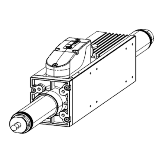
6.3 Mechanische Installation-XTA 6.3 Mechanical Installation-XTA The outline drawing of the XTA is shown in Figure 2.1. Abbildung 2.1. zeigt eine Zeichnung der Baureihe XTA. Die Baureihe XTA besteht aus der Primäreinheit It comprises the forcer with an integrated plastic sleeve bearing and the thrust rod. - Seite 20 6.3 Mechanical Installation-XTA 6.3 Mechanische Installation-XTA ACTUATOR ENVELOPE = (2 X STROKE ) + 319 (See Note 1) 4 MTG HOLES M6 x 10 DEEP 258.0 40.3 40.0 59.0 27.0 4 MTG HOLES M4 x 8 DEEP XTA3804 29.0 PITCH TYP 33.0 83.0 8 MTG HOLES...
-
Seite 21: Mechanical Installation-Xtb
6.4 Mechanical Installation-XTB 6.4 Mechanische Installation-XTB In Bild 2.2 ist eine Skizze von XTB dargestellt. The XTB is shown in Figure 2.2. It comprises the forcer and the thrust rod. With the addition of thrust rod XTB besteht aus der Primäreinheit und der Ma- supports and a linear bearing a moving forcer solution gnetstange. - Seite 22 6.4 Mechanical Installation-XTB 6.4 Mechanische Installation-XTB 218.0 40.3 59.0 XTB3804 29.0 PITCH TYP 4 MTG HOLES 70.0 M4 x 8 DEEP 33.0 EITHER SIDE 8 MTG HOLES 174.0 M4 x 8 DEEP 70.0 THRUST ROD 289.0 XTB3806 29.0 PITCH TYP 76.0 8 MTG HOLES 239.0...
-
Seite 23: Electrical Installation
6.5 Electrical Installation 6.5 Elektrische Installation All electrical connections to the XTA and XTB are made Alle elektronischen Verbindungen zur XTA und XTB via two cables, see Figure 2.3a and Baureihe erfolgen durch zwei Kabel, siehe Figure 2.3b. One cable carries power to Bild 2.3a und Bild 2.3b. - Seite 24 Connection of XTA/XTB to XSL and XTL-S Verbindung von XTA/XTB mit XSL und XTL-S XENUS XSL POWER CABLE TO J2 TO J8 SENSOR CABLE XENUS XTL-S POWER CABLE TO J2 TO J8 SENSOR CABLE Figure 2.3a - Schematic showing connection of XTA / XTB to the Xenus Amplifier XSL and Xenus Amplifier XTL-S./ Abbildung 2.3a-Schematische Darstellung der Verbindung XTA/XTB mit dem Xenus Verstärker XSL und dem Xenus Verstärker XTL-S.
- Seite 25 Connection of XTA/XTB to XSJ-S Verbindung von XTA/XTB mit XSJ-S and Parker Compax 3 und Parker Compax 3 XENUS MICRO PANEL XSJ-S POWER CABLE TO J2 SENSOR CABLE TO J6 PARKER COMPAX 3 SENSOR CABLE TO X3 POWER CABLE TO X13 Figure 2.3b - Schematic showing connection of XTA / XTB to the Xenus Micro Panel Amplifier XSJ-S and the Parker Compax 3 Amplifier/Abbildung 2.3b-Schematishce Darstellung der Verbindung XTA/XTB mit dem Xenus Micro Panel Verstärker XSJ-S und dem Parker Compax 3 Verstärker...
-
Seite 26: Maintenance/Service
7. Maintenance/Service 7. Wartung/Service 7.1 Maintenance 7.1 Wartung 7.2. XTA 7.2 XTA The XTA is low maintenance and as such requires only Die XTA Baureihe erfordert geringe Wartung und minimal periodic inspection. muss daher nur minimalen periodischen Inspektionen unterzogen werden. Das integrierte Lager ist trocken- The integral bearing is dry running, requiring no laufend und benötigt keine Schmierung. -
Seite 27: Cable Replacement
WARNING! WARNUNG! ISOLATE AND DISCONNECT ISOLIEREN UND TRENNEN SIE ALLE ALL SOURCES OF ELECTRICAL SUPPLY STROMQUELLEN BEVOR SIE MIT DER ARBEIT AM BEFORE WORKING ON THE EQUIPMENT. GERÄT BEGINNEN. 7.4 CABLE REPLACEMENT 7.4. KABEL-AUSTAUSCH • If a cable needs to be replaced it will be necessary •... -
Seite 28: Replacement
7.5 Replacement 7.5 Einbau von Einzelteilen • Re-fitting is the reverse of the removal procedure. Der Wiedereinbau ist der Umkehrprozess des Aus- bauvorgangs. • Führen Sie die neuen Kabel durch die Kabelver- • Feed the new cable(s) through the cable gland. schraubung. -
Seite 29: Service
7.6 SERVICE 7.6 SERVICE Should you need to return any items to Dunkermotoren Sollten Sie irgendwelche Teile zu Dunkermotoren Linear Systems, before doing so, please call our Sales Linearsysteme zurückgeben müssen, kontaktieren Sie Department. davor bitte unseren Vertrieb. Please note that when returning items it is recommended Bitte beachten Sie bitte, dass bei Rückgaben that the original packaging be used. -
Seite 30: Appendices
Für Anfragen bezüglich Gebrauch und Anwendung des For enquiries relating to the operation and use of the hier beschriebenen ServoTube 38, wenden Sie sich ServoTube 38 described in this Manual please contact bitte an den Dunkermotoren Vetrieb. the Dunkermotoren Sales Department. -
Seite 31: Troubleshooting Chart
8.2 TROUBLESHOOTING CHART 8.2 PROBLEMBEHANDLUNG Check to see if the problem you are experiencing is Kontrollieren Sie ob das auftretende Problem in der listed in the chart below. If the problem cannot be untenstehenden Tabelle aufgeführt ist. Falls das solved with reference to this chart, contact the customer Problem nicht mit Hilfe dieser Tabelle gelöst werden services department. -
Seite 32: Terms & Abbreviations
8.3 TERMS AND ABBREVIATIONS TERM DESCRIPTION OF TERM Peak force Peak force is the force produced when the peak current is applied to the forcer. It is the product of Force constant (N/Apk) and Peak current (Apk). The forcer is not moving, there is no forced cooling and no additional heat-sinking. - Seite 33 8.3 TERMS AND ABBREVIATIONS (CONTINUED) Maximum phase Maximum phase temperature is the maximum operating temperature for the motor phases. It is limited to temperature provide a safe operating temperature for the magnets. is the temperature rise from the motor housing to the motor phases for an input power of 1 watt to thphase-houslng thphase-houslng the motor.
-
Seite 34: Begriffserklärungen & Abkürzungen
8.3 BEGRIFFSERKLÄRUNGEN & ABKÜRZUNGEN Begriff Beschreibung Spitzen-Schubkraft Die Spitzen-Schubkraft ist diejenige Kraft, die aufgebracht wird, wenn der Motor mit Spitzenstrom versorgt wird. Es ist das Produkt aus der Kraftkonstante (N/A pk) und des Spitzenstroms (A pk). Die Primäreinheit bewegt sich nicht, es erfolgt keine Zwangskühlung und der Motor hat keinen zusätzlichen Kühlkörper. Die Dauer des Spitzenstroms ist thermisch begrenzt und daher nur möglich für einen Zeitraum von 1 Sekunde. -
Seite 35: Abkürzungen
8.3 BEGRIFFSERKLÄRUNGEN & ABKÜRZUNGEN (FORTGESETZT) Maximale Die maximale Phasentemperatur ist die maximale Betriebstemperatur für die Motorenphasen. Um eine sichere Phasentemperatur Betriebstemperatur für die Magnete sicherzustellen, ist diese begrenzt. Rth Phase-Gehäuse Rth Phase-Gehäuse ist der Temperaturanstieg innerhalb des Motorgehäuses in Relation zur Temperatur der Motorphasen, bei einer Energiezufuhr zum Motor von 1 Watt. -
Seite 36: Scope Of Delivery And Accessories
9. Service & Support 9. Service & Support Should you have any questions or problems, please Bei Fragen und Problemen stehen Ihnen folgende An- contact: sprechpartner zur Verfügung: - Your local Dunkermotoren sales outlet - Ihre zuständige Vertretung - Your local Dunkermotoren key account manager - Ihr zuständiger Dunkermotoren Key Account - Our hardware support department Manager... -
Seite 37: Contact Information
Version 02.2012 www.dunkermotoren.com... -
Seite 38: Vertretungen Und Vertriebsgesellschaften
Representatives, Distributors and Offi ces Vertretungen und Vertriebsgesellschaften Germany Europe and Overseas Sachsen-Anhalt Nord, Berlin, Brandenburg Korea Austria Dunkermotoren GmbH Dunkermotoren Dunkermotoren Korea Ltd. Allmendstraße 11 · 79848 Bonndorf Armin Keller - Sales Representative Austria Parkview 19th, 1908-Ho, #6, Jeongja-dong, Tel.