Inhaltsverzeichnis
Werbung
Quicklinks
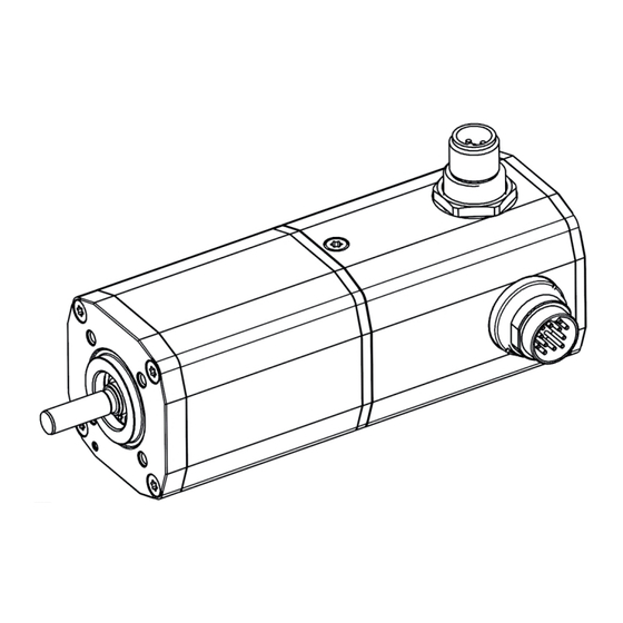
BG45 PI
Instruction Manual
Motor with parametrizable motion
controller integrated
Betriebsanleitung
Motor mit integriertem parametrierbarem
Motioncontroller
Dunkermotoren GmbH
Allmendstraße 11 · D-79848 Bonndorf/Schwarzwald
www.dunkermotoren.com · info@dunkermotoren.de
Phone +49 (0) 7703 930-0 · Fax +49 (0) 7703 930-210/212
Motor
Part No.
45x15
88545.01XXX
45x30
88545.02XXX
Werbung
Inhaltsverzeichnis

Verwandte Anleitungen für Metek BG45 PI


Inhaltszusammenfassung für Metek BG45 PI
- Seite 1 BG45 PI Motor Part No. 45x15 88545.01XXX 45x30 88545.02XXX Instruction Manual Motor with parametrizable motion controller integrated Betriebsanleitung Motor mit integriertem parametrierbarem Motioncontroller Dunkermotoren GmbH Allmendstraße 11 · D-79848 Bonndorf/Schwarzwald www.dunkermotoren.com · info@dunkermotoren.de Phone +49 (0) 7703 930-0 · Fax +49 (0) 7703 930-210/212...
-
Seite 2: Inhaltsverzeichnis
2 About this document ������������������������������� 8 2 Über dieses Dokument����������������������������8 3 General description ��������������������������������� 9 3 Allgemeine Beschreibung ����������������������9 ....... 9 3.1 Motor series BG45 PI ......9 3.1 Motorbaureihe BG45 PI ..... 10 ........ 10 3.2 Explanations of terms used 3.2 Begriffserklärungen... - Seite 3 ..28 ....28 8.2.8 Gegenstecker mit Anschlussleitung 8.2.8 Mating connector with cable 8.2.9 Prinzipschaltbild Spannungsversorgung 8.2.9 Schematic circuit power supply ..........29 ..........29 BG45 PI BG45 PI ........30 ...........30 8.3 Digitaleingänge 8.3 Digital inputs ..30 ..30 8.3.1 Schematic circuit of the digital inputs 8.3.1 Prinzipschaltung der Digitaleingänge...
- Seite 4 ........40 - Projektfenster .........40 - Project Window 12 Beschreibung der 12 Description of the Betriebsarten �������������������������������������� 42 Operating Modes ���������������������������������42 ........43 ........43 12.1 Der Converter 12.1 The converter ......45 12.2 Brake Management ......45 12.2 Brake management ..45 ....45 12.2.1 Steuerung über Betriebsfreigabe 12.2.1 Control through power enable...
- Seite 5 ......73 ......73 „Brake management“ „brake management“ 12.5.7 Parameter Group 12.5.7 Parametergruppe ......73 ......73 „Position feedback“ „Position feedback“ 12.5.8 Parameter Group 12.5.8 Parametergruppe ......74 ......74 „Positions [counts]“ „Positions [counts]“ ....75 ....75 12.6 „Modulo“ Positioning Mode 12.6 Positioniermodus „Modulo“ ....78 ....78 12.6.1 “Moving”...
- Seite 6 12.8.7 Parameter Group 12.8.7 Parametergruppe ......100 ......100 „Position feedback“ „Position feedback“ 12.9 „Velocity Standard“ 12.9 Geschwindigkeitsmodus ........101 ......101 Velocity Mode „Velocity Standard“ ..103 ..103 12.9.1 „Velocity source“ Parameter Group 12.9.1 Parametergruppe „Velocity source“ ..104 ..104 12.9.2 „Current [mA]“ Parameter Group 12.9.2 Parametergruppe „Current [mA]“...
- Seite 7 ........123 ..........123 accessories Zubehör ....124 ....124 13.5 EC Declaration of Conformity 13.5 EG-Konformitätserklärung Version 06.2015 www.dunkermotoren.com...
-
Seite 8: About This Document
2 Über dieses Dokument 2 About this document Die vorliegende Betriebsanleitung stellt Ihnen die These operating instructions introduce you to the parametrierbaren Antriebe vor und informiert Sie parametrizable drives and inform you about all über alle Schritte zur Installation der Antriebe und zur necessary steps for installation and carrying out initial Durchführung erster Funktionstests. -
Seite 9: General Description
• Die Motoren BG45 PI können auf Wunsch auch • On request, the motors in the BG45 PI range can mit Planeten-, oder Schneckengetrieben mit einer be combined with planetary or worm gears, which Vielzahl fein abgestimmter Untersetzungen are available in a very wide range of reduction kombiniert werden. -
Seite 10: Explanations Of Terms Used
3�2 Explanations of terms used 3.2 Begriffserklärungen Begriff Erklärung Term Explanation Defaultwerte Voreingestellte Werte Defaultwerte Preset values Digitaler Lagegeber. Eine Digital position indicator. An internal logic processes a interne Logik erzeugt aus dem Signal von Foto- signal from photodiodes to Incremental encoder Inkrementalgeber produce two square-wave... -
Seite 11: Proper Use
3�3 Proper use 3.3 Bestimmungsgemäße Verwendung - The BG45 PI motor is a supplied part and may be - Der Motor BG45 PI ist ein Zulieferteil und darf in installed into (industrial) machinery and equipment in der beschriebenen Konfiguration in Maschinen the described configuration. -
Seite 12: Safety Instructions
4 Safety instructions 4 Sicherheitshinweise Before commissioning, it is Vor der Inbetriebnahme sind unbe- essential that the safety instructions dingt die Sicherheitshinweise zu lesen in the relevant section are read and und zu beachten! Eine Nichtbeach- understood, and then observed! tung kann zu Gefahren bei Personen Non-observance can result in danger oder Beschädigungen an der... -
Seite 13: Technical Data, Accessories
5 Technical data, accessories 5 Technische Daten, Zubehör 5�1 Electrical data 5�1 Elektrische Daten Non-destructive 12V: 0 ... 35 VDC Zerstörungsfreier Spannungs- 12V: 0 ... 35 VDC voltage range power supply 24V: 0 ... 58 VDC bereich Leistungsversorgung 24V: 0 ...58 VDC Operating voltage range 12V: 9 ... -
Seite 14: Load Diagram Output Shaft
5.2.1 Load diagram output shaft 5�2�1 Wellenbelastungsdiagramm The permissible shaft load Die zulässigen Wellenbelastungen (axial / radial) depends on the (axial/radial) sind abhängig von der speed. Please consider the following Drehzahl. Beachten Sie hierzu das chart. nachfolgende Diagramm. NOTICE HINWEIS The maximum bearing loads should Bei Gehäusetemperaturen >... -
Seite 15: Motor Specification
5.4 Motor specification 5.4 Motorspezifikationen Exceeding of the maximum permitted Überschreiten der maximal zulässigen continuous current! Dauerströme! Die Folge: Consequence: Kann zur Zerstörung des Antriebs The drive may be CAUTION VORSICHT führen. destroyed. ► Mind the maximum permitted ► Die maximal zulässigen Dauerströme beachten! continuous current! BG45x15 PI... -
Seite 16: Bg45X30 Pi
BG45x30 PI BG45x30 PI Nominal voltage 12 V Nennspannung 12 V Nominal power 82,4 W Nennleistung 82,4 W Nominal torque 24,6 Ncm Nenndrehmoment 24,6 Ncm Recommended empfohlener 0 ... 6500 rpm 0 ... 6500 U/min speed control range Drehzahlregelbereich Nominal speed 3190 rpm Nenndrehzahl 3190 U/min... -
Seite 17: Optional Attachments
5�5 Optional attachments 5�5 Optionale Anbauten Worm gear Schneckengetriebe The worm gear is extremely quiet. In many applica- Die Schneckengetriebe zeichnen sich durch hohe tions, the gear shaft shifted by 90° compared to the Laufruhe aus. Bei vielen Anwendungen ist die um 90° motor shaft is ideal with regard to structural aspects. -
Seite 18: Accessories
5�6 Accessories 5�6 Zubehör Starter Kit Starter Kit SNR Starter Kit with software 96800 05024 SNR Starterkit mit Software 96800 05024 With the „Motion Starter Kit“, the user has the possibi- Das „Starter Kit“ bietet dem Anwender die Möglichkeit lity to program the motor quickly and easily. einer schnellen und einfachen Programmierung des To control a motor using a PC, a starter kit with CAN Motors. -
Seite 19: Types Of Operation
6� Betriebsarten 6� Types of operation Unter anderem sind folgende Betriebsarten möglich: The following types of operation are possible: - Current mode - Current/torque mode - Velocity mode - Velocity mode - Position mode - Position mode 6.1 Betrieb mit Inkremental- 6�1 Operation with incremental geber encoder... -
Seite 20: Protective Functions
7� Schutzfunktionen 7� Protective functions Der Motor besitzt verschiedene Schutzfunktionen, um The motor has several protection functions to avoid Schäden durch Überbelastung zu vermeiden. Jede damages by overload. dieser Schutzfunktionen wird nachfolgend im Detail Each protection function is described below in detail. beschrieben. -
Seite 21: Over Voltage Cut-Off
7�5 Überspannungsabschaltung 7.5 Over voltage cut-off Leistungsversorgung power stage supply Wenn die Versorgungsspannung die 60 V überschrei- If the power stage supply exceeds 35 V (12 V version) tet, schaltet die Leistungsstufe ab. Der Fehler kann / 58 V (24 V version) the power stage is disabled. The bestätigt werden, nachdem die Versorgungsspannung error can be confirmed after the power stage supply unter 60V gefallen ist. -
Seite 22: Voltage Controlled Braking
7.7 Voltage controlled braking 7�7 Spannungsgeregeltes Bremsen As the motor includes a 4Q controller it feeds back Da der Antrieb einen 4Q-Regler besitzt, speist er energy to the DC link during braking operation. beim Bremsen Energie in den Zwischenkreis zurück. If the DC link reaches the limit value (motor voltage) Erreicht die Zwischenkreisspannung (Motorspannung) the current will be reduced in order to stop a further... -
Seite 23: Installation
8 Installation 8 Installation Vor der Inbetriebnahme sind unbe- Before commissioning, it is dingt die Sicherheitshinweise zu essential that the safety instructions lesen und zu beachten! Eine in the relevant section are read and Nichtbeachtung kann zu Gefahren understood, and then observed! WARNUNG WARNING bei Personen oder Beschädigungen... -
Seite 24: Motor Connector Connection
8�1�2 Anbindung Motorstecker 8�1�2 Motor connector connection Während das Kabel mit dem Motorkabel verbunden During connecting of the cable with the motor note wird, achten Sie auf das Symbol H (Siehe Zeichnung). symbol H (see drawing). 8�1�3 Winkellage Motorstecker 8�1�3 Angle adjustment motor connector Description Pos�... -
Seite 25: Electrical Installation
8�2 Elektrische Installation 8�2 Electrical Installation 8.2.1 Elektromagnetische Verträglichkeit 8.2.1 Electro-magnetic compatibility Beim Betrieb des Motors, bzw. der gesamten During operation of the drive respectively the entire Anlage entstehen elektromagnetische system electromagnetic interference is created. Störstrahlungen. Diese können ohne geeignete Without suitable protective measures, this can influ- Schutzmaßnahmen die Signale von Steuerleitungen ence signals in control cables and parts of the instal-... -
Seite 26: Power- And Logic Supply
8.2.3 Power- and logic supply 8.2.3 Leistungs- und Logikversorgung Plug: Stecker: Round plug M16, 12-pin Rundstecker M16, 12-polig 8�2�4 Pin Assignment 8�2�4 Steckerbelegung www.dunkermotoren.de Version 06.2015... -
Seite 27: Mating Connector With Cable
8�2�5 Mating connector with cable 8�2�5 Gegenstecker mit Anschlussleitung Turning of the connector of more Verdrehen des Anschlußstecker über than +/- 45°! einen Drehwinkel von +/- 45°! Consequence: Die Folge: Short circuit, short circuit to frame or Kurzschluss, Körperschluss oder CAUTION VORSICHT malfunction by unfixed wires at the... -
Seite 28: Parametrization Connector
8�2�7 Parametrization connector 8�2�7 Parametrierschnittstelle Motorstecker: Rundstecker M12 Motor plug Round plug M12 Connector-pin Function Stecker-Pin Funktion n.c. n.c. n.c. n.c. n.c. n.c. Signal- High Signal- High Signal- Low Signal- Low 8�2�8 Mating connector with cable 8�2�8 Gegenstecker mit Anschlussleitung Connecting cable (Article code 16597 57033) Anschlusskabel M12 (Sachnummer 16597 57033) www.dunkermotoren.de... -
Seite 29: Schematic Circuit Power Supply
The grey section of the schematic circuit shows the Der grau hinterlegte Ausschnitt des Prinzipschaltbildes connection of a BG45 PI. It is also possible to zeigt die Anschlüsse eines BG45 PI. Es können auch connect in series more BG-motors as shown. -
Seite 30: Digital Inputs
8�3 Digital inputs 8.3 Digitaleingänge 8�3�1 Schematic circuit of the digital inputs 8.3.1 Prinzipschaltung der Digitaleingänge Dotted line: Optional if switched to ground Gestrichelt: Optional für massegeschaltete Eingänge RBE at logic supply 24V: 1,2kR RBE bei Logik Versorgung 24V: 1,2kR RBE at logic supply 12V: 2,2kR RBE bei Logik Versorgung 12V: 2,2kR 8�4 Digital outputs... -
Seite 31: Drive Assistant
9 Drive Assistant 9 Drive Assistant 9�1 Introduction 9.1 Einführung With the Drive Assistant control program, Dunkermo- Mit dem Steuerungsprogramm Drive Assistant bietet toren provides a comprehensive software tool with Dunkermotoren ein umfangreiches Softwaretool, mit which it is possible to extensively configure the vario- dem es möglich ist verschiedene Typen von BG-Mo- us types of BG motors. -
Seite 32: Description Of The
10 Description of the 10 Beschreibung des Main Window Hauptfensters 10�1 Description of the General 10�1 Beschreibung der allgemeinen Parameter Groups - Main Window Parametergruppen - Hauptfenster The following parameter groups are common to all modes: Allen Modi gemeinsam sind folgende Parametergruppen: Group Field „Projects“... -
Seite 33: Description Of The
11 Description of the 11 Beschreibung des Project Window Projektfensters 11�1 Description of the General 11�1 Beschreibung der allgemeinen ParameterGroups - Project Window Parametergruppen - Projektfenster „Connected“ Group Field Gruppenfeld „Connected“ In the “Connected” group field, information can be Im Gruppenfeld „Connected“ finden sie Informationen found about the hardware and software versions. - Seite 34 „Connection“ Group Field Gruppenfeld „Connection“ The “MOTOR STOP” button is a function that serves Die Schaltfläche „MOTOR STOP“ ist eine Funktion, to bring the connected motor to an immediate stand- die dazu dient, bei angeschlossenem Motor einen still. sofortigen Stillstand herbeizuführen. „Selected“...
- Seite 35 Device“ Group Field Gruppenfeld „Device“ Additionally it exists the possibility to start and desi- Zusätzlich besteht im Feld „Device“ die Möglichkeit gnate new modis under the Group Field „Device“. Modis neu zu starten und zu benennen. Under „Create new Settings“, new modis can be star- Unter „Create new Settings“...
- Seite 36 “I/O” Group Field Gruppenfeld „I/O“ In the “I/0” group field, the number of the actual Im Gruppenfeld „I/0“ wird die tatsächlich an dem availlable analogue or digital inputs and outputs of the Antrieb verfügbare Anzahl der analogen bzw. digitalen motor are displayed. Ein- und Ausgänge des Motors dargestellt.
-
Seite 37: Description Of The File Cards
11.2 Description of the file cards 11.2 Beschreibung der Karteikarten Within the project window, there are further Innerhalb des Projektfensters gibt es weitere Unterka- sub-categories, the file cards. With this file cards it is tegorien, die Karteikarten. Diese Karteikarten lassen, possible to configure exactly the individual operating bezüglich einzelner Betriebsarten, weitere Einstell- modes with further set ups and support of the com-... -
Seite 38: Description Of The File Card „Drive Parameters
Einstellungen von Regelparametern The default values are so selected, that the drive angezeigt. Die Defaultwerte wurden so gewählt, dass BG45 PI works at standard requirement on dynamics der Antrieb BG45 PI bei Standardanforderungen an and inertia stable. Dynamik und Massenträgheit stabil arbeitet. -
Seite 39: Description Of The File Card „Device Info
Spline shows the measuring points in a linear curve, Spline veranschaulicht die Messpunkte in einer line- in which the individual polynomials (measuring points) aren Kurve, in der die einzelnen Polynomen (Mess- are linked interdependent. punkte) abhängig voneinander verkettet sind. Bezier shows the measuring points in a parametric Bezier veranschaulicht die Messpunkte in einer pa- modelled curve, which shows the desired values in a rametrisch modellierten Kurve, die die gewünschten... -
Seite 40: Description Of The Menu Bar
11�3 Description of the Menu Bar 11.3 Beschreibung der Menüleiste - Project Window - Projektfenster Menu „File“ Menü „File“ In the “File” menu, the user has the possibility of sto- Im „File“-Menü hat der Anwender die Möglichkeit, sei- ring or deleting his configuration parameter set under ne konfigurierten Parametersätze abzuspeichern. - Seite 41 Menu „Help“ Menü „Help“ In the “Help” menu, the user has the possibility to look Im „Help“-Menü hat der Anwender die Möglichkeit, after the pin assignemt („Pin Assignment“) as well as die Pinbelegung („Pin Assignment“), sowie die Ein- the Interface description („I/O Interface description“). gangsbelegung („I/O Interface description“) einzusehen.
-
Seite 42: Description Of The Operating Modes
12 Description of the 12 Beschreibung der Operating Modes Betriebsarten Functional Description of the Operating Modes Funktionsbeschreibung Betriebsmodi With the operating modes, for example, various posi- Bei den Betriebsmodi können beispielsweise ver- tions in the transducer increments can be defined. The schiedene Positionen in Geberinkrementen definiert zero position is previously determined by a reference werden. -
Seite 43: The Converter
12�1 The converter 12�1 Der Converter The converter can be identified by the following Der Converter ist erkennbar an folgendem symbol. Symbol. After clicking on the icon it pop up the following Es erscheint nach dem Klick auf das Symbol folgende mask. - Seite 44 Enter in a further input-field the position In einem weiteren Eingabefeld kann nun ein (here e.g. 10) and choose in the drop-down menu Positionswert (in diesem Beispiel 10) und im Drop- the unit of measurement. downmenü daneben eine Einheit ausgewählt werden. From the values gear ratio, shaft or wheel diameter, Aus den Werten Getriebeuntersetzung, Wellen- bzw.
-
Seite 45: Brake Management
12�2 Brake Management 12�2 Brake management The following adjustments in the Parameter Group Nachfolgende Einstellungen sind in der „brake management“ are possible. Parametergruppe „brake management“ möglich. No brake No brake There is no brake module on the motor. Es ist keine Bremse angeschlossen. Control through Power Enable Control through Power Enable The brake is opened automatically... -
Seite 46: Steuerung Über Bewegung
This example shows the use of the Dieses Beispiel zeigt die Verwendung des Bremsen- brake management via power enable simultaneous management mittels Betriebsfreigabe und movement. gleichzeitiger Bewegung Command for the power enable and / or movement. Kommando für die Betriebsfreigabe und/oder eine The power enable starts immediately. -
Seite 47: Brake Management Delays
Dieses Beispiel zeigt die Verwendung des Bremsen- This example shows the use of the brake manage- management mittels Betriebsfreigabe und Bewegung. ment via power enable and motion. At the end of the Am Ende der Bewegung wird die Betriebsfreigabe movement the power enable automatically is locked automatisch gesperrt (disable). -
Seite 48: Standard" Positioning Mode
12.3 „Standard“ Positioning Mode 12.3 Positioniermodus „Standard“ The “Standard” positioning mode is an easily Bei dem Positioniermodus „Standard“ handelt es sich confi- gurable operating mode that is extremely well- um einen leicht konfigurierbaren Betriebsmodus, der suited for positioning tasks with up to six positions. sich für Positionieraufgaben von bis zu sechs Positi- onen hervorragend eignet. - Seite 49 IN 1 IN 2 IN 3 Function IN 1 IN 2 IN 3 Funktion Clear error and Error beseitigen und STOP STOP Begin homing Homing beginnen Position 1 Position 1 Position 2 Position 2 Position 3 Position 3 Position 4 Position 4 Position 5 Position 5...
-
Seite 50: Moving" Parameter Group
Im Folgenden finden sie alle konfigurierbaren In the following, detailed descriptions of all configurable parameter groups can be found: Parametergruppen ausführlich beschrieben: 12.3.1 Parametergruppe „Moving“ 12.3.1 „Moving“ Parameter Group In the “Moving” parameter group, the user has the In der Parametergruppe „Moving“, wird dem An- possibility of making basic settings of the type of wender ermöglicht, grundlegende Einstellungen der movement. -
Seite 51: Current [Ma]" Parameter Group
12.3.2 „Current [mA]“ Parameter Group 12.3.2 Parametergruppe „Current [mA]“ In the “Current [mA]” parameter group, the user has In der Parametergruppe „Current [mA]“ wird dem the possibility of making basic settings of the current Anwender ermöglicht, grundlegende Einstellungen der strength. Stromstärke vorzunehmen. -
Seite 52: Parameter Group „Motor Power
12.3.4 Parameter Group „Motor Power“ 12.3.4 Parametergruppe „Motor power“ After a configured motor has reached a position (by a Nachdem ein konfigurierter Motor eine Position er- drive to or stop command), there are two possibilities reicht (durch Anfahren oder einen Stop-Befehl), gibt with which this position can be handled by the motor. - Seite 53 If, after referencing, the motor is Wird der Motor nach der Referenzie- pushed to a position outside the rung im stromlosen Zustand in eine operating zone with the power supply Position außerhalb des Betriebsbe- cut off, it will not be possible to reichs verschoben ist es nicht NOTICE HINWEIS...
- Seite 54 The method Actual position as homed position Die Methode Actual position as homed position (Position-zero) sets the current position as homing (Position-zero) setzt die aktuelle Position als position with value 0 Homing Position mit Wert 0. The method Actual position as homed position Die Methode Actual position as homed position (Position-zero) sets the current position as homing (Position-actual) setzt die aktuelle Position als...
-
Seite 55: Parameter Group „Brake Management
12�3�6 Parameter Group 12�3�6 Parametergruppe „Brake management“ „brake management“ The following adjustments in the Parameter Group Nachfolgende Einstellungen sind in der „brake management“ are possible. Parametergruppe „brake management“ möglich. No brake No brake There is no brake module on the motor. Es ist keine Bremse angeschlossen. -
Seite 56: Parameter Group
12�3�7 Parametergruppe 12�3�7 Parameter Group „Position feedback“ „Position feedback“ Zur Positionsrückführung stehen folgende The following encoders for position feedback are Gebersysteme zur Verfügung: available: • Interne Hall-Sensoren • Internal hall sensors • Internen lnkremental Encoder • Internal incremental encoder • AE (Absolutwertgeber) •... -
Seite 57: Stepper" Positioning Mode
12.4 Positioniermodus „Stepper“ 12.4 „Stepper“ Positioning Mode The “Stepper” positioning mode is an easily confi- Bei dem Positioniermodus „Stepper“ handelt es sich um einen leicht zu konfigurierenden Betriebsmodus, gured operating mode that is extremely well-suited to simple positioning operations. In “Stepper” mode, the der sich für einfache Positionierungen hervorragend eignet. - Seite 58 Um die binäre Eingabe zu erleichtern wird der fünfte To facilitate binary entries, the fifth digital input is used digitale Eingang zur Bestätigung der Binäreinstellung to confirm the binary settings. Only when the benutzt. Erst wenn durch IN 4 die Freigabe gegeben enable is given by IN 4 is the pending command ist, wird der angesteuerte Befehl ausgeführt.
-
Seite 59: Moving" Parameter Group
12.4.1 „Moving“ Parameter Group 12.4.1 Parametergruppe „Moving“ In der Parametergruppe „Moving“, wird dem An- In the “Moving” parameter group, the user has the possibility of making basic settings of the type of wender ermöglicht, grundlegende Einstellungen der movement. Bewegungsart zu tätigen. Direction gibt die Drehrichtung des Motors an. -
Seite 60: Current [Ma]" Parameter Group
12.4.2 „Current [mA]“ Parameter Group 12.4.2 Parametergruppe „Current [mA]“ In the “Current [mA]” parameter group, the user has In der Parametergruppe „Current [mA]“ wird dem the possibility of making basic settings of the current Anwender ermöglicht, grundlegende Einstellungen der strength. Stromstärke vorzunehmen. -
Seite 61: Parameter Group "Motor Power
12.4.4 Parameter Group “Motor Power” 12.4.4 Parametergruppe „Motor power“ After a configured motor has reached a position (by a Nachdem ein konfigurierter Motor eine Position er- drive to or stop command), there are two possibilities reicht (durch Anfahren oder einen Stop-Befehl), gibt with which this position can be handled by the motor. - Seite 62 If, after referencing, the motor is Wird der Motor nach der Referenzie- pushed to a position outside the rung im stromlosen Zustand in eine operating zone with the power supply Position außerhalb des Betriebsbe- cut off, it will not be possible to reichs verschoben ist es nicht NOTICE HINWEIS...
- Seite 63 The method Actual position as homed position Die Methode Actual position as homed position (Position-zero) sets the current position as homing (Position-zero) setzt die aktuelle Position als position with value 0 Homing Position mit Wert 0. The method Actual position as homed position Die Methode Actual position as homed position (Position-zero) sets the current position as homing (Position-actual) setzt die aktuelle Position als...
-
Seite 64: Parameter Group „Brake Management
12�4�6 Parameter Group 12�4�6 Parametergruppe „Brake management“ „brake management“ The following adjustments in the Parameter Group Nachfolgende Einstellungen sind in der „brake management“ are possible. Parametergruppe „brake management“ möglich. No brake No brake There is no brake module on the motor. Es ist keine Bremse angeschlossen. -
Seite 65: Positions [Counts]
12�4�8 Parameter Group 12�4�8 Parametergruppe „Positions [counts]“ „Positions [counts]“ In the “Positions” parameter group, the user has the In der Parametergruppe „Positions“ wird dem Anwen- possibility of storing a position in the motor. This can der ermöglicht, eine Positionierung auf dem Motor zu then be optionally driven to via the motor control. -
Seite 66: Positioning Mode „Left-Right
12.5 Positioning Mode „Left-Right“ 12.5 Positioniermodus „Left-Right“ The “Left-Right” positioning mode is a versatile Bei dem Positioniermodus „Left-Right“ handelt es sich configurable operating mode that makes possible for um einen vielfältig konfigurierbarer Betriebsmodus the user to drive back and forth between two different der es dem Anwender auf einfache Weise ermöglicht positions in a simple manner. - Seite 67 To facilitate the binary entries, the fifth digital input is Um die binäre Eingabe zu erleichtern wird der fünfte used to confirm the binary settings. Only when the digitale Eingang zur Bestätigung der Binäreinstellung enable is given by IN 4 is the pending command per- benutzt.
-
Seite 68: Moving" Parameter Group
In the following, detailed descriptions of all Im Folgenden finden sie alle konfigurierbaren Para- configurable parameter groups can be found: metergruppen ausführlich beschrieben: 12.5.1 “Moving” Parameter Group 12.5.1 Parametergruppe „Moving“ In the “Moving” parameter group, the user has the In der Parametergruppe „Moving“, wird dem An- possibility of making basic settings of the type of wender ermöglicht, grundlegende Einstellungen der movement. -
Seite 69: Current [Ma]" Parameter Group
12.5.2 “Current [mA]” Parameter Group 12.5.2 Parametergruppe „Current [mA]“ In der Parametergruppe „Current [mA]“ wird dem In the “Current [mA]” parameter group, the user has the possibility of making basic settings of the current Anwender ermöglicht, grundlegende Einstellungen der strength. Stromstärke vorzunehmen. -
Seite 70: Parameter Group "Motor Power
12.5.4 Parameter Group “Motor Power” 12.5.4 Parametergruppe „Motor power“ After a configured motor has reached a position (by a Nachdem ein konfigurierter Motor eine Position er- drive to or stop command), there are two possibilities reicht (durch Anfahren oder einen Stop-Befehl), gibt with which this position can be handled by the motor. - Seite 71 If, after referencing, the motor is Wird der Motor nach der Referenzie- pushed to a position outside the rung im stromlosen Zustand in eine operating zone with the power supply Position außerhalb des Betriebsbe- cut off, it will not be possible to reichs verschoben ist es nicht NOTICE HINWEIS...
- Seite 72 The method Actual position as homed position Die Methode Actual position as homed position (Position-zero) sets the current position as homing (Position-zero) setzt die aktuelle Position als position with value 0 Homing Position mit Wert 0. The method Actual position as homed position Die Methode Actual position as homed position (Position-zero) sets the current position as homing (Position-actual) setzt die aktuelle Position als...
-
Seite 73: Brake Management
12�5�6 Parameter Group 12�5�6 Parametergruppe „Brake management“ „brake management“ The following adjustments in the Parameter Group Nachfolgende Einstellungen sind in der „brake management“ are possible. Parametergruppe „brake management“ möglich. No brake No brake There is no brake module on the motor. Es ist keine Bremse angeschlossen. -
Seite 74: Positions [Counts]
12�5�8 Parameter Group 12�5�8 Parametergruppe „Positions [counts]“ „Positions [counts]“ In the “Positions” parameter group, the user has the In der Parametergruppe „Positions“ wird dem Anwen- possibility of storing a position in the motor. This can der ermöglicht, eine Positionierung auf dem Motor zu then be optionally driven to via the motor control. -
Seite 75: Modulo" Positioning Mode
12.6 „Modulo“ Positioning Mode 12.6 Positioniermodus „Modulo“ The “Modulo” positioning mode is an easily configured Bei dem Positioniermodus „Modulo“ handelt es sich operating mode that makes possible for the user to um einen leicht zu konfigurierenden Betriebsmodus parameterise positionings adapted to the situation and der es dem Anwender ermöglicht situationsange- drive to them in the required manner. - Seite 76 IN 1 IN 2 IN 3 IN 4 Funktion IN 1 IN 2 IN 3 IN 4 Function Error beseitigen und Clear error and STOP STOP Homing beginnen Begin homing Position 1 Position 1 Position 2 Position 2 Position 3 Position 3 Position 4 Position 4...
- Seite 77 The “Modulo” positioning mode is a versatile function Hinter dem Positioniermodus „Modulo“ steht eine viel- that will be explained with the following example of a seitige Funktionsweise, welche am folgenden Beispiel tool changer. eines Werkzeugwechslers erläutert wird. MODULO MODULO MODE OF OPERATION FUNKTIONSWEISE Rotation is configured with the aid of positions Umdrehung wird mit Hilfe von Positionen konfiguriert...
-
Seite 78: Moving" Parameter Group
All configurable parameter groups are described in Im Folgenden finden sie alle konfigurierbaren detail in the following: Parametergruppen ausführlich beschrieben: 12.6.1 “Moving” Parameter Group 12.6.1 Parametergruppe „Moving“ In the “Moving” parameter group, the user has the pos- In der Parametergruppe „Moving“, wird dem Anwender sibility of making basic settings of the type of movement. -
Seite 79: Ramps [Ms / 1000Rpm]" Parameter Group
12�6�3 Parametergruppe 12.6.3 “Ramps [ms / 1000rpm]” „Ramps [ms / 1000rpm]“ Parameter Group Alle ansteuerbaren Positionen im Positioniermodus In the positioning mode, all positions are approached werden mit Hilfe von Rampen (beschleunigende und with the aid of acceleration and braking ramps. The abbremsende) exakt angefahren. -
Seite 80: Motor Power" Parameter Group
12.6.5 Parametergruppe „Motor power“ 12.6.5 “Motor Power” Parameter Group Nachdem ein konfigurierter Motor eine Position er- After a configured motor has reached a position (by a reicht (durch Anfahren oder einen Stop-Befehl), gibt drive to or stop command), there are two possibilities es zwei Möglichkeiten, wie mit dieser Position von with which this position can be handled by the motor. -
Seite 81: Homing" Parameter Group
12.6.6 „Homing“ Parameter Group 12.6.6 Parametergruppe „Homing“ For the exact configuration of position movements, a Zur exakten Konfiguration von Positionsfahrten, muss homing procedure must first be initiated for a motor. bei einem Motor zunächst ein Homing-Verfahren In this homing procedure, a reference point must be eingeleitet werden. - Seite 82 The Searching Limit Switch in Negative direction Die Methode Searching Limit Switch in Negativ method allows the motor to search opposite to the direction veranlasst den Motor dazu, entgegen der direction of rotation for a limit switch (characterised by Drehrichtung nach einem Limitschalter (charakterisiert a raising/falling edge) and to set the reference point durch Steigende/Fallende Flanke) zu suchen und sich when it is reached.
-
Seite 83: Modulo" Parameter Group
12.6.7 “Modulo” Parameter Group 12.6.7 Parametergruppe „Modulo“ In the “Modulo” parameter group, the user can adapt In der Parametergruppe „Modulo“ kann der Anwender the method by which a motor performs a positioning to die Art, wie ein Motor eine Positionierung vornimmt, his needs. -
Seite 84: Parameter Group „Brake Management
12�6�8 Parametergruppe 12�6�8 Parameter Group „brake management“ „Brake management“ Nachfolgende Einstellungen sind in der The following adjustments in the Parameter Group Parametergruppe „brake management“ möglich. „brake management“ are possible. No brake No brake Es ist keine Bremse angeschlossen. There is no brake module on the motor. Control through Power Enable Control through Power Enable Die Bremse öffnet automatisch bei... -
Seite 85: Complete Positioning Command" Positioning Mode
12.7 „Complete Positioning 12�7 Positioniermodus Command“ Positioning Mode „Complete Positioning Command“ The „Complete Positioning Command“ positioning Bei dem Positioniermodus „Complete Positioning mode is an easily configurable operating mode that Command“ handelt es sich um einen leicht konfi- is extremly well-suited for absolute and for relative gurierbaren Betriebsmodus, der sich für absolute, positionings. - Seite 86 IN 1 IN 2 IN 3 IN 4 Function IN 1 IN 2 IN 3 IN 4 Funktion Clear error and Error beseitigen und STOP STOP Begin Homing Homing beginnen Position 1 Position 1 Position 2 Position 2 Position 3 Position 3 Position 4 Position 4...
-
Seite 87: Moving" Parameter Group
12.7.1 „Moving“ Parameter Group 12.7.1 Parametergruppe „Moving“ In the “Moving” parameter group, the user has the In der Parametergruppe „Moving“, wird dem Anwen- possibility of making basic settings of the type of der ermöglicht, grundlegende movement. Einstellungen der Bewegungsart zu tätigen. Direction gives the direction of rotation of the motor;... -
Seite 88: Homing" Parameter Group
12.7.2 „Homing“ Parameter Group 12.7.2 Parametergruppe „Homing“ For the exact configuration of position movements, a Zur exakten Konfiguration von Positionsfahrten, muss homing procedure must first be initiated for a motor. bei einem Motor zunächst ein Homing-Verfahren In this homing procedure, a reference point must be eingeleitet werden. - Seite 89 The Searching Limit Switch in Negative direction Die Methode Searching Limit Switch in Negativ method allows the motor to search opposite to the direction veranlasst den Motor dazu, entgegen der direction of rotation for a limit switch (characterised by Drehrichtung nach einem Limitschalter (charakterisiert a raising/falling edge) and to set the reference point durch Steigende/Fallende Flanke) zu suchen und sich when it is reached.
-
Seite 90: Motor Power" Parameter Group
12.7.3 „Motor Power“ Parameter Group 12.7.3 Parametergruppe „Motor Power“ After a configured motor has reached a position (by a Nachdem ein konfigurierter Motor eine Position er- drive to or stop command), there are two possibilities reicht (durch Anfahren oder einen Stop-Befehl), gibt with which this position can be handled by the motor. -
Seite 91: Ramp [Ms/1000Rpm]" Parameter Group
12.7.5 „Ramp [ms/1000rpm]“ 12�7�5 Parametergruppe Parameter Group „Ramp [ms/1000rpm]“ In positioning mode, all achievable positions are Alle ansteuerbaren Positionen im Positioniermodus approached with ramps. The ramps are given in [ms werden mit Hilfe von Rampen angefahren. / 1000rpm] (milliseconds per 1000 revolutions per Die Rampen werden in [ms / 1000rpm] (Millisekunden minute). -
Seite 92: Positions" Parameter Group
12.7.7 „Positions“ Parameter Group 12.7.7 Parametergruppe „Positions“ In the “Positions” parameter group, the user has the In der Parametergruppe „Positions“ wird dem Anwen- possibility of storing 14 drive sets in the motor. These der ermöglicht, 14 verschiedene Fahrsätze auf dem can then be optionally driven via a subordinate motor Motor abzuspeichern. -
Seite 93: Parameter Group „Position Feedback
12�7�8 Parameter Group 12�7�8 Parametergruppe „Position feedback“ „Position feedback“ The following encoders for position feedback are Zur Positionsrückführung stehen folgende available: Gebersysteme zur Verfügung: • Internal hall sensors • Interne Hall-Sensoren • Internal incremental encoder • Internen lnkremental Encoder • AE (absolute encoder) •... -
Seite 94: Positioning By Event" Positioning Mode
12.8 „Positioning by Event“ 12�8 Positioniermodus Positioning Mode „Positioning by Event“ The „Positioning by Event“ mode is an easily configu- Bei dem Positioniermodus „Positioning by Event“ rable operating mode that makes it possible for the handelt es sich um einen leicht konfigurierbaren user to stop (positioning) an application in motion via Betriebsmodus der es dem Anwender ermöglicht, eine an event. - Seite 95 Die Ansteuerung der Einstellungen erfolgt hierbei über The activation of the settings takes place via an analo- gue or a digital input that is coded as follows: einen analogen Eingang oder digitale Eingänge, die wie folgt aufgeschlüsselt sind: IN 0 IN 1 Function IN 0...
-
Seite 96: Moving" Parameter Group
If a brake is present and brake Sofern vorhanden und aktiviertem management is activated, the brake is Bremsmanagement, wird die Bremse über den controlled via the output OUT0. Ausgang OUT0 gesteuert. OUT0 Function OUT0 Funktion No voltage at Brake Keine Spannung an (0V) Bremse (0V) Voltage at Brake... -
Seite 97: Motor Power" Parameter Group
For more information see chapter 12.2 Für mehr Informationen siehe Kapitel 12.2 12.8.3 „Motor Power“ Parameter Group 12.8.3 Parametergruppe „Motor Power“ After a configured motor has reached a position (by a Nachdem ein konfigurierter Motor eine Position er- drive to or stop command), there are two possibilities reicht (durch Anfahren oder einen Stop-Befehl), gibt with which this position can be handled by the motor. -
Seite 98: Current [Ma]" Parameter Group
12.8.4 “Current [mA]” Parameter Group 12.8.4 Parametergruppe „Current [mA]“ In the “Current [mA]” parameter group, the user has In der Parametergruppe „Current [mA]“ wird dem the possibility of making basic settings of the current Anwender ermöglicht, grundlegende Einstellungen der strength. Stromstärke vorzunehmen. -
Seite 99: Move" Parameter Group
12.8.6 Parametergruppe „Move“ 12.8.6 „Move“ Parameter Group In der Parametergruppe „Move“ hat der Anwender die In the Parameter Group „Move“ the user has the pos- Möglichkeit einen Fahrbefehl und das definierte Positi- sibility to to parameterize the drive command and the onieren nach einem Ereignis (IN2, IN3) zu defined position after an event (IN2, IN3). -
Seite 100: Position Feedback
Position [Counts] hier wird dem Anwender ermög- Position [counts], the user has the possibility to defi- licht die Positionierung nach dem Ereignis (IN2, IN3) ne the positioning after the event (IN2, IN3). The value for this position movement are given in zu definieren. -
Seite 101: Velocity Standard" Velocity Mode
12�9 Geschwindigkeitsmodus 12.9 „Velocity Standard“ Velocity Mode „Velocity Standard“ Bei dem Geschwindigkeitsmodus „Velocity Standard“ The “Velocity Standard” mode is an easily configured operating mode that makes it possible for the user to handelt es sich um einen leicht konfigurierbaren Betriebsmodus der es dem Anwender ermöglicht, configure three motor velocities in a simple manner by über das Setzen von verschiedenen Parametern, auf setting various parameters and adapting them to his... - Seite 102 IN 2 IN 3 IN 4 Function IN 2 IN 3 IN 4 Funktion Velocity 1 Geschwindigkeit 1 Velocity 2 Geschwindigkeit 2 Velocity 3 Geschwindigkeit 3 Alternatively you may activate the settings by analo- Alternativ kann die Ansteuerung über analoge Eingän- gue inputs: ge geschehen: IN3/AI+...
-
Seite 103: Velocity Source" Parameter Group
Im Folgenden finden sie alle konfigurierbaren Para- In the following, all configurable parameter groups are metergruppen ausführlich beschrieben: described in detail: 12.9.1 Parametergruppe „Velocity source“ 12.9.1 „Velocity source“ Parameter Group In der Parametergruppe „Velocity source“ wird dem With the “Velocity Source” parameter group, the user Anwender die Möglichkeit gegeben, über die Steue- is given the possibility of deciding which control vari- rungsvariante des Geschwindigkeitsmodus zu ent-... -
Seite 104: Current [Ma]" Parameter Group
12.9.2 „Current [mA]“ Parameter Group 12.9.2 Parametergruppe „Current [mA]“ In the “Current [mA]” parameter group, the user has In der Parametergruppe „Current [mA]“ wird dem the possibility of making basic settings of the current Anwender ermöglicht, grundlegende Einstellungen der strength. Stromstärke vorzunehmen. -
Seite 105: Parameter Group „Brake Management
12�9�4 Parameter Group 12�9�4 Parametergruppe „Brake management“ „brake management“ The following adjustments in the Parameter Group Nachfolgende Einstellungen sind in der „brake management“ are possible. Parametergruppe „brake management“ möglich. No brake No brake There is no brake module on the motor. Es ist keine Bremse angeschlossen. -
Seite 106: Velocity Multi" Velocity Mode
12.10 „Velocity Multi“ 12�10 Geschwindigkeitsmodus Velocity Mode „Velocity Multi“ The “Velocity Multi” velocity mode is a versatile Bei dem Geschwindigkeitsmodus „Velocity Multi“ han- configurable operating mode which allows the user to delt es sich um ein vielseitig konfigurierbarer Betriebs- configure up to eight motor velocities by setting para- modus der es dem Anwender ermöglicht, über Setzen meters and adapt them to his needs. - Seite 107 IN 2 IN 3 IN 4 Function IN 2 IN 3 IN 4 Funktion Velocity 1 Geschwindigkeit 1 Velocity 2 Geschwindigkeit 2 Velocity 3 Geschwindigkeit 3 Velocity 4 Geschwindigkeit 4 Velocity 5 Geschwindigkeit 5 Velocity 6 Geschwindigkeit 6 Velocity 7 Geschwindigkeit 7 Velocity 8 Geschwindigkeit 8...
-
Seite 108: Velocity Source" Parameter Group
In the following, all configurable parameter groups are Im Folgenden finden sie alle konfigurierbaren Para- described in detail: metergruppen ausführlich beschrieben: 12.10.1 “Velocity source” 12�10�1 Parametergruppe Parameter Group „Velocity source“ In “Velocity Source” parameter group, the user is In der Parametergruppe „Velocity source“ wird dem given the possibility of deciding which control variant Anwender die Möglichkeit gegeben, über die Steue- to use for the velocity mode. -
Seite 109: Current [Ma]" Parameter Group
12.10.2 „Current [mA]“ 12�10�2 Parametergruppe Parameter Group „Current [mA]“ In the “Current [mA]” parameter group, the user has In der Parametergruppe „Current [mA]“ wird dem the possibility of making basic settings of the current Anwender ermöglicht, grundlegende Einstellungen der strength. Stromstärke vorzunehmen. -
Seite 110: Parameter Group „Brake Management
12�10�4 Parameter Group 12�10�4 Parametergruppe „Brake management“ „brake management“ The following adjustments in the Parameter Group Nachfolgende Einstellungen sind in der „brake management“ are possible. Parametergruppe „brake management“ möglich. No brake No brake There is no brake module on the motor. Es ist keine Bremse angeschlossen. -
Seite 111: Current Standard" Torque Mode
12�11 Drehmomentmodus 12.11 „Current Standard“ „Current Standard“ Torque Mode Bei dem Drehmomentmodus „Current Standard“ han- The “Current Standard” torque mode is an easily delt es sich um einen leicht konfigurierbaren Betriebs- configurable operating mode with which the user can modus der es dem Anwender ermöglicht, über Setzen readily set parameters to configure three torques, von Parametern Veränderung, auf einfache Weise, and vary them to suit his needs, by setting the current... - Seite 112 IN 2 IN 3 IN 4 Function IN 2 IN 3 IN 4 Funktion Torque 1 Drehmoment 1 Torque 2 Drehmoment 2 Torque 3 Drehmoment 3 Alternatively you may activate the settings by analo- Alternativ kann die Ansteuerung über analoge Eingän- gue inputs: ge geschehen: IN3/AI+...
-
Seite 113: Current Source" Parameter Group
In the following, all configurable parameter groups are Im Folgenden finden sie alle konfigurierbaren Para- described in detail: metergruppen ausführlich beschrieben: 12.11.1 “Current Source” 12�11�1 Parametergruppe Parameter Group „Current source“ With the “Current source” parameter group, the user is In der Parametergruppe „Current source“ wird dem given the possibility of deciding which control variant Anwender die Möglichkeit gegeben, über die Steue- to use for the torque mode. -
Seite 114: Velocity [Rpm]" Parameter Group
12.11.2 “Velocity [rpm]” Parameter Group 12.11.2 Parametergruppe „Velocity [rpm]“ With the “Velocity [rpm]” parameter group, it is possi- In der Parametergruppe „Velocity [rpm]“ wird dem ble for the user to make basic settings for the velocity. Anwender ermöglicht, grundlegende Einstellungen der Geschwindigkeit vorzunehmen. -
Seite 115: Parameter Group „Brake Management
12�11�4 Parameter Group 12�11�4 Parametergruppe „Brake management“ „brake management“ The following adjustments in the Parameter Group Nachfolgende Einstellungen sind in der „brake management“ are possible. Parametergruppe „brake management“ möglich. No brake No brake There is no brake module on the motor. Es ist keine Bremse angeschlossen. -
Seite 116: Current Multi" Torque Mode
12.12 „Current Multi“ 12�12 Drehmomentmodus Torque Mode „Current Multi“ The “Current Multi” torque mode is a versatile confi- Bei dem Drehmomentmodus „Current Multi“ handelt gurable operating mode that gives the user a simple es sich um einen vielseitig konfigurierbaren Betriebs- way of configuring eight torques by setting the current modus der es dem Anwender ermöglicht, über Setzen strength and of adapting them to his needs by chan-... - Seite 117 IN 2 IN 3 IN 4 Function IN 2 IN 3 IN 4 Funktion Torque 1 Drehmoment 1 Torque 2 Drehmoment 2 Torque 3 Drehmoment 3 Torque 4 Drehmoment 4 Torque 5 Drehmoment 5 Torque 6 Drehmoment 6 Torque 7 Drehmoment 7 Torque 8 Drehmoment 8...
-
Seite 118: Current Source" Parameter Group
Im Folgenden finden sie alle konfigurierbaren Para- In the following, all configurable parameter groups are metergruppen ausführlich beschrieben: described in detail: 12.12.1 Parametergruppe „Current source“ 12.12.1 “Current Source” Parameter Group In der Parametergruppe „Current source“ wird dem With the “Current source” parameter group, the user is Anwender die Möglichkeit gegeben, über die Steue- given the possibility of deciding which control variant rungsvariante des Drehmomentmodus zu entschei-... -
Seite 119: Velocity [Rpm]" Parameter Group
12.12.2 “Velocity [rpm]” Parameter Group 12.12.2 Parametergruppe „Velocity [rpm]“ With the “Velocity [rpm]” parameter group, it is possi- In der Parametergruppe „Velocity [rpm]“ wird dem ble for the user to make basic settings for the velocity. Anwender ermöglicht, grundlegende Einstellungen der Geschwindigkeit vorzunehmen. -
Seite 120: Parameter Group „Brake Management
12�12�4 Parameter Group 12�12�4 Parametergruppe „Brake management“ „brake management“ The following adjustments in the Parameter Group Nachfolgende Einstellungen sind in der „brake management“ are possible. Parametergruppe „brake management“ möglich. No brake No brake There is no brake module on the motor. Es ist keine Bremse angeschlossen. -
Seite 121: Maintenance & Service
13 Maintenance & Service 13 Wartung & Service 13�1 Maintenance, taking out of 13.1 Wartung, Außerbetriebsetzung service and disposal und Entsorgung Maintenance: Wartung: This drive does not require maintenance if the Bei korrektem Einbau ist der Antrieb wartungsfrei. Der installation is carried out correctly. The drive is lubri- Antrieb ist lebensdauergeschmiert. -
Seite 122: Error Search
13�2 Error search 13.2 Fehlersuche Error/ Fehler Cause/ Ursache Check/ Test The motor hasn‘t been turning/ Motor wrong connected/ Check the connection/ Der Motor dreht sich nicht Motor nicht korrekt verkabelt Prüfen Sie die Verkabelung Motor not identified/ USB is not installed/ Using „Drive Assistant CD“... -
Seite 123: Service & Support
13�3 Service & Support 13�3 Service & Support Should you have any questions or problems, please Bei Fragen und Problemen stehen Ihnen folgende An- contact: sprechpartner zur Verfügung: - Your local Dunkermotoren sales outlet - Ihre zuständige Vertretung - Your local Dunkermotoren - Ihr zuständiger Dunkermotoren key account manager Key Account Manager... -
Seite 124: Eg-Konformitätserklärung
13.5 EG-Konformitätserklärung 13�5 EC Declaration of Conformity www.dunkermotoren.de Version 06.2015... - Seite 125 Notes Notizen Version 06.2015 www.dunkermotoren.com...
- Seite 126 Dunkermotoren GmbH | Allmendstraße 11 | D-79848 Bonndorf/Schwarzwald Phone +49 (0) 7703 930-0 | Fax +49 (0) 7703 930-210/212 | info@dunkermotoren.com...