Inhaltsverzeichnis
Werbung
Verfügbare Sprachen
Verfügbare Sprachen
Quicklinks
Air-Conditioners For Building Application
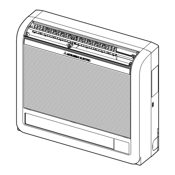
INDOOR UNIT
PFFY-P·VKM-E
INSTALLATION MANUAL
For safe and correct use, please read this installation manual thoroughly before installing the air-conditioner
unit.
INSTALLATIONSHANDBUCH
Zum sicheren und ordnungsgemäßen Gebrauch der Klimaanlage das Installationshandbuch gründlich
durchlesen.
MANUEL D'INSTALLATION
Veuillez lire le manuel d'installation en entier avant d'installer ce climatiseur pour éviter tout accident et vous
assurer d'une utilisation correcte.
INSTALLATIEHANDLEIDING
Voor een veilig en juist gebruik moet u deze installatiehandleiding grondig doorlezen voordat u de airconditioner
installeert.
MANUAL DE INSTALACIÓN
Para un uso seguro y correcto, lea detalladamente este manual de instalación antes de montar la unidad de
aire acondicionado.
MANUALE DI INSTALLAZIONE
Per un uso sicuro e corretto, leggere attentamente questo manuale di installazione prima di installare il condizionatore
d'aria.
E°XEIPI¢IO O¢H°IøN E°KATA™TA™H™
°È· ·ÛÊ¿ÏÂÈ· Î·È ÛˆÛÙ‹ ¯Ú‹ÛË, ·Ú·Î·Ï›ÛÙ ‰È·‚¿ÛÂÙ ÚÔÛ¯ÙÈο ·˘Ùfi ÙÔ ÂÁ¯ÂÈÚ›‰ÈÔ ÂÁηٿÛÙ·Û˘
ÚÈÓ ·Ú¯›ÛÂÙ ÙËÓ ÂÁηٿÛÙ·ÛË Ù˘ ÌÔÓ¿‰·˜ ÎÏÈÌ·ÙÈÛÌÔ‡.
MANUAL DE INSTALAÇÃO
Para segurança e utilização correctas, leia atentamente este manual de instalação antes de instalar a unidade
de ar condicionado.
MONTAJ ELK‹TABI
Emniyetli ve do¤ru biçimde nas›l kullan›laca¤›n› ö¤renmek için lütfen klima cihaz›n› monte etmeden önce bu
elkitab›n› dikkatle okuyunuz.
РУКОВОДСТВО ПО УСТАНОВКЕ
Для осторожного и правильного использования прибора необходимо тщательно ознакомиться с данным
руководством по установке до выполнения установки кондиционера.
For use with the R410A, R407C & R22
Bei Verwendung von R410A, R407C & R22
A utiliser avec le R410A, R407C et le R22
Bij gebruik van R410A, R407C & R22
Para utilizar con el R410A, R407C y el R22
Uso del refrigerante R410A, R407C e R22
FOR INSTALLER
FÜR INSTALLATEURE
POUR L'INSTALLATEUR
VOOR DE INSTALLATEUR
PARA EL INSTALADOR
PER L'INSTALLATORE
°π∞ ∞À∆√¡ ¶√À ∫∞¡∂π ∆∏¡ ∂°∫∞∆∞™∆∞™∏
PARA O INSTALADOR
MONTÖR ‹Ç‹N
ДЛЯ УСТАНОВИТЕЛЯ
°È· ¯Ú‹ÛË Ì ٷ R410A, R407C Î·È R22
Para utilizaçao com o R410A, R407C e o R22
R410A, R407C ve R22 ile beraber kullanmak için
Для использования с моделями R410A, R407С и R22
English
Deutsch
Français
Nederlands
Español
Italiano
∂ÏÏËÓÈο
Português
Türkçe
Русский
Werbung
Kapitel
Inhaltsverzeichnis

Verwandte Anleitungen für Mitsubishi Electric PFFY-P-VKM-E


Inhaltszusammenfassung für Mitsubishi Electric PFFY-P-VKM-E
- Seite 1 Air-Conditioners For Building Application INDOOR UNIT PFFY-P·VKM-E For use with the R410A, R407C & R22 °È· ¯Ú‹ÛË Ì ٷ R410A, R407C Î·È R22 Bei Verwendung von R410A, R407C & R22 Para utilizaçao com o R410A, R407C e o R22 A utiliser avec le R410A, R407C et le R22 R410A, R407C ve R22 ile beraber kullanmak için Bij gebruik van R410A, R407C &...
-
Seite 2: Inhaltsverzeichnis
• If the air conditioner is installed in a small room, measures must be taken to • Use only accessories authorized by Mitsubishi Electric and ask the dealer or prevent the refrigerant concentration from exceeding the safety limit even if an authorized technician to install them. -
Seite 3: Installing The Indoor Unit
3. Installing the indoor unit (mm) 3.1. Indoor unit mounting bracket installation • Install the bracket firmly to the wall structure (stud, etc.). (Fig. 3-1) • Use a level to install the mounting bracket horizontally. • Install the indoor unit 150 mm or below from the floor. A Indoor unit mounting bracket Note: To prevent the indoor unit mounting bracket from vibrating slightly, be sure to... -
Seite 4: Refrigerant Pipe
3. Installing the indoor unit 2) For right downward or left downward piping (Fig. 3-8) (The following figure is a view of the bottom of the indoor unit from above.) A When the unit is installed on the wall. B When the unit is installed on the floor. Fig. -
Seite 5: Drainage Piping Work
• If the indoor unit is installed in a high location such as a high-rise apartment, strong winds may cause the drain water to flow back through the drain hose and leak from the unit. If necessary, contact your nearest Mitsubishi Electric repre- sentative for the optional parts to prevent this problem. -
Seite 6: Embedding The Indoor Unit In A Wall
5. Drainage piping work • Insert the drain hose all the way to the base of the drain pan. (Fig. 5-4) Make sure that the drain hose is securely caught on the projection in the hole in the drain pan. Fig. -
Seite 7: Electrical Work
7. Electrical work 7.1. Indoor unit (Fig. 7-1) 1 Remove the electrical cover. • Remove one screw holding the electrical cover, then move the cover. • Remove one screw holding the cord clamp, then move the clamp. 2 Connect the power line, control line from the outdoor unit, and remote con- trol lines. -
Seite 8: Types Of Control Cables
7. Electrical work 7.3. Setting addresses (Fig. 7-4) (Be sure to operate with the main power turned OFF.) 220V 240V • There are two types of rotary switch setting available: setting addresses 1 to 9 and CN43 over 10, and setting branch numbers. Note: Please set the switch SW5 according to the power supply voltage. -
Seite 9: Air Outlet Selection
9. Air outlet selection With this function, air comes out simultaneously from the upper and lower air outlets so that the room can be cooled or heated effectively. This function is set using the switch SWC on the address board. 220V 240V CN43... -
Seite 10: Sicherheitsvorkehrungen
• Wenn die Anlage in einem kleinen Raum installiert wird, müssen Maßnahmen er- • Zur Verdrahtung die angegebenen Kabel verwenden. griffen werden, damit die Kältemittelkonzentration auch bei Kältemittelaustritt den • Nur von Mitsubishi Electric zugelassenes Zubehör verwenden, und dieses durch Sicherheitsgrenzwert nicht überschreitet. Ihren Händler oder eine Vertragswerkstatt einbauen lassen. -
Seite 11: Anbringung Der Innenanlage
3. Anbringung der Innenanlage (mm) 3.1. Installation der Montagehalterung für Innenanlage • Die Halterung fest an der Wandstruktur (Bolzen usw.) installieren. (Fig. 3-1) • Die Montagehalterung mit Hilfe einer Wasserwaage waagerecht installieren. • Die Innenanlage höchstens 150 mm vom Boden entfernt installieren. A Montagehalterung für Innenanlage Hinweis: Um ein Vibrieren der Montagehalterung der Innenanlage zu vermeiden, sicherstel-... -
Seite 12: Abdichtung Der Bohrungen
3. Anbringung der Innenanlage 2) Verrohrung rechts abwärts oder links abwärts (Fig. 3-8) (Die folgende Abbildung zeigt den Boden der Innenanlage von oben.) A Bei Wandinstallation des Geräts. B Bei Bodeninstallation des Geräts. Fig. 3-8 3) Verrohrung links (Fig. 3-9) 4) Verrohrung rechts (Fig. -
Seite 13: Verrohrung Der Dränage
4. Kältemittelrohrleitung 1) Verrohrung rechts abwärts (Fig. 4-3) 2) Sonstige Verrohrung (Fig. 4-4) A Bänder B Rohrisolationen C Die Isolation entfernen. • Die Anschlussrohre isolieren und an der Rückseite der Innenanlage verlegen, damit sie nicht mit der Frontplatte in Berührung kommen. •... -
Seite 14: Wandeinbau Der Innenanlage
5. Verrohrung der Dränage • Den Ablassschlauch entlang der Ablaufwanne verlegen. (Fig. 5-4) Sicherstellen, dass der Ablassschlauch fest auf der Nase in der Bohrung der Ablauf- wanne sitzt. Fig. 5-4 • Den Ablassschlauch diagonal unter den Anschlussrohren verlegen. (Fig. 5-5) A Rohrleitungsband B Kältemittelleitung C Ablassschlauch... -
Seite 15: Elektroarbeiten
7. Elektroarbeiten 7.1. Innenanlage (Fig. 7-1) 1 Entfernen Sie die Abdeckung der Elektronik. • Entfernen Sie die Schraube, die die Abdeckung der Elektronik hält, und nehmen Sie dann die Abdeckung ab. • Entfernen Sie die Schraube, die die Kabelklemme hält, und entfernen Sie dann die Klem- 2 Schließen Sie die Netzleitung, die Steuerleitung von der Außenanlage und die Leitungen der Fernbedienung an. -
Seite 16: Steuerkabelarten
7. Elektroarbeiten 7.3. Adressen einsetzen (Fig. 7-4) (Dafür sorgen, dass bei den Arbeiten der Netzstrom auf AUS geschaltet ist.) 220V 240V • Zur Einstellung gibt es zwei Arten von Rotationsschaltern: Zur Einstellung der Adressen CN43 von 1 bis 9 und über 10 sowie zur Einstellung der Abzweigungsnummern. Hinweis: Bitte den Schalter SW5 je nach Netzspannung einstellen: •... -
Seite 17: Luftauslass
9. Luftauslass Mit dieser Funktion strömt die Luft gleichzeitig aus den oberen und unteren Luftauslässen, so dass der Raum effektiver gekühlt oder geheizt werden kann. Diese Funktion wird mit dem Schalter SWC auf der Adressplatine eingestellt. 220V 240V CN43 CN82 1 2 3 4 5 6 7 8 9 10 SW12 SW11... -
Seite 18: Consignes De Sécurité
• Utilisez les câbles mentionnées pour les raccordements. • Si le climatiseur est installé dans une pièce relativement petite, certaines mesures • Utiliser uniquement les accessoires agréés par Mitsubishi Electric et demander à doivent être prises pour éviter que la concentration de réfrigérant ne dépasse le votre revendeur ou à... -
Seite 19: Installation De L'appareil Intérieur
3. Installation de l’appareil intérieur (mm) 3.1. Installation du support de flxation de l’appareil interieur • Installez solidement le support sur la structure murale (goujon, etc.). (Fig. 3-1) • Utilisez un niveau pour installer le support de fixation horizontalement. • Installez l’appareil intérieur à 150 mm au plus du sol. A Support de fixation de l’appareil intérieur Remarque : Pour éviter que le support de fixation de l’appareil intérieur ne vibre légèrement,... -
Seite 20: Travaux Pour L'installation Des Tuyaux De Réfrigérant
3. Installation de l’appareil intérieur 2) Pour la tuyauterie inclinee vers le bas cote droit ou gauche (Fig. 3-8) (Le schéma suivant présente une vue plongeante de la partie inférieure de l’appareil intérieur.) A Lorsque l’appareil est fixé au mur. B Lorsque l’appareil est fixé... -
Seite 21: Mise En Place Du Tuyau D'écoulement
étrange (murmure) par vents violents ou lorsqu’un ventilateur, etc., est utilisé dans une habitation bien isolée. Le cas échéant, veuillez con- tacter votre revendeur Mitsubishi Electric le plus proche pour savoir quels accessoires acheter pour éviter ce problème. - Seite 22 5. Mise en place du tuyau d’écoulement • Insérez complètement le flexible de vidange au fond du bac de vidange. (Fig. 5-4) Veillez à ce que le flexible de vidange soit bien fixé dans l’extension du trou du bac de vidange.
-
Seite 23: Installations Électriques
7. Installations électriques 7.1. Apparail intérieur (Fig. 7-1) 1 Retirez le couvercle du boîtier électrique. • Retirez la vis qui maintient le couvercle du boîtier électrique, puis déposez ce dernier. • Retirez la vis qui maintient l’attache-câble, puis retirez ce dernier. 2 Raccorder la ligne d’alimentation électrique, la ligne de contrôle de l’appareil ex- térieur, et les lignes de la télécommande. -
Seite 24: Types De Câbles De Commandes
7. Installations électriques 7.3. Configuration des adresses (Fig. 7-4) (Toujours effectuer ces opérations lorsque le système est hors tension.) 220V 240V • Il existe deux types de réglages de commutateurs rotatifs disponibles, pour le réglage CN43 des adresses de 1 à 9 et au-dessus de 10 et pour le réglage du nombre de ramifications. Remarque: Veuillez régler l’interrupteur SW5 selon la tension de l’alimentation. - Seite 25 9. Sélection de la sortie d’air Grâce à cette fonction, l’air est pulsé simultanément des sorties d’air supérieure et infé- rieure de façon à refroidir ou chauffer rapidement la pièce. Vous pouvez sélectionner cette fonction grâce au commutateur SWC situé sur le panneau de l’adresse. 220V 240V CN43...
-
Seite 26: Veiligheidsvoorschriften
• Gebruik de gespecificeerde verbindingskabels voor de verbindingen. • Als de airconditioner in een kleine ruimte wordt geïnstalleerd, moeten er maat- • Gebruik alleen onderdelen die door Mitsubishi Electric zijn goedgekeurd en regelen worden genomen om te voorkomen dat de concentratie koelstof in de vraag de zaak waar u het apparaat gekocht heeft of een erkend bedrijf om ze ruimte hoger is dan de veiligheidsgrens bij eventuele lekkage van koelstof. -
Seite 27: Het Binnenapparaat Installeren
3. Het binnenapparaat installeren (mm) 3.1. Aanbrengen van de montagebeugel voor de binnenunit • Breng de beugel stevig op de wand aan (met draadeinden en dergelijke). (Fig. 3-1) • Stel de montagebeugel met een waterpas horizontaal af. • Monteer de binnenunit op maximaal 150 mm boven de vloer. A Montagebeugel voor de binnenunit Opmerking: Om mogelijke trillingen van de montagebeugel voor de binnenunit te voorko-... -
Seite 28: De Koelstofpijpen Aansluiten
3. Het binnenapparaat installeren 2) Voor pijpen rechts naar beneden of links naar beneden (Fig. 3-8) (In de volgende afbeelding wordt de bodem van de binnenunit van bovenaf weer- gegeven.) A Als de unit aan de wand wordt aangebracht. B Als de unit op de vloer wordt aangebracht. Fig. -
Seite 29: Koelpijp
Neem indien nodig contact op met uw dichtstbijzijnde verte- genwoordiging van Mitsubishi Electric. Zij kunnen optionele onderdelen bieden om dit probleem op te lossen. -
Seite 30: De Binnenunit In Een Wand Inbouwen
5. Installatie van Draineerbuizen • Voer de afvoerslang helemaal in tot aan de onderkant van het afvoerreservoir. (Fig. 5-4) Let erop dat de afvoerslang stevig klemt in het uitsteeksel in het gat van het afvoer- reservoir. Fig. 5-4 • Leid de afvoerslang diagonaal onder de verbindingspijpen door. (Fig. 5-5) A Tape voor de pijpen B Koelpijpen C Afvoerslang... -
Seite 31: Elektrische Aansluitingen
7. Elektrische aansluitingen 7.1. Binnenapparaat (Fig. 7-1) 1 Verwijder de afdekking voor elektrische delen. • Verwijder een schroef terwijl u de afdekking vasthoudt, en verplaats daarna de afdekking. • Verwijder een schroef terwijl u de kabelklem vasthoudt, en verplaats daarna de klem. -
Seite 32: Types Regelkabels
7. Elektrische aansluitingen 7.3. De aansluitadressen instellen (Fig. 7-4) (Zorg ervoor dat er geen stroom op het apparaat staat als u de adressen instelt.) 220V 240V • Er zijn twee types draaibare schakelinstellingen beschikbaar: voor het instellen CN43 van adressen 1 tot 9 en groter dan 10, en voor het instellen van aftakkingsnummers. Opmerking: Stel de schakelaar SW5 in op het juiste voltage van de netvoeding. -
Seite 33: Keuze Luchtuitlaten
9. Keuze luchtuitlaten Met deze functie kunt u de lucht tegelijkertijd uit de bovenste en onderste luchtuitlaat laten komen zodat de ruimte effectief gekoeld of verwarmd wordt. U stelt de functie in met de schakelaar SWC op de adressenplaat. 220V 240V CN43 CN82... -
Seite 34: Medidas De Seguridad
• Utilice los cables especificados para la instalación eléctrica. marse medidas para prevenir que la concentración de refrigerante exceda • Utilice sólo accesorios autorizados por Mitsubishi Electric y pida a su distri- los límites de seguridad incluso si hubiese fugas. -
Seite 35: Instalación De La Unidad Interior
3. Instalación de la unidad interior (mm) 3.1. Instalación del soporte de montaje de la unidad interior • Instale el soporte firmemente en la estructura de la pared (montante, etc.). (Fig. 3-1) • Utilice un nivel para colocar el soporte en horizontal. •... -
Seite 36: Tubo De Refrigerante
3. Instalación de la unidad interior 2) Para tuberías derecha o izquierda hacia abajo (Fig. 3-8) (La siguiente figura es una vista desde arriba de la base de la unidad interior.) A Si la unidad está instalada en pared. B Si la unidad está instalada en el suelo. Fig. -
Seite 37: Tubería De Drenaje
En caso necesario, póngase en contacto con su representante de Mitsubishi Electric más cercano para obtener las piezas opcionales necesarias para evitar este problema. -
Seite 38: Empotrado De La Unidad Interior En Una Pared
5. Tubería de drenaje • Inserte la manguera de drenaje a lo largo de la base del depósito de drenaje. (Fig. 5-4) Asegúrese de que la manguera de drenaje está bien sujeta en la parte saliente del orificio del depósito de drenaje. Fig. -
Seite 39: Trabajo Eléctrico
7. Trabajo eléctrico 7.1. Unidad interior (Fig. 7-1) 1 Retire la cubierta eléctrica. • Quite el tornillo que sujeta la cubierta eléctrica y retírela. • Quite el tornillo que sujeta la abrazadera de cable y retírela. 2 Conecte la línea de alimentación, la línea de control de la unidad exterior y las líneas del controlador remoto. -
Seite 40: Tipos De Cables De Control
7. Trabajo eléctrico 7.3. Configuración de las direcciones (Fig. 7-4) (Asegúrese de trabajar con la corriente desconectada) 220V 240V • Hay disponibles dos tipos de configuraciones para los conmutadores giratorios: CN43 uno para la configuración de las direcciones 1 a 9 y por encima de 10 y otro para configurar los números de los ramales. -
Seite 41: Selección De La Salida De Aire
9. Selección de la salida de aire Con esta función, el aire se expulsa simultáneamente por las salidas superior e inferior, de modo que la sala se pueda refrigerar o calentar de forma eficaz. Esta función se establece con el conmutador SWC del tablero de direcciones. 220V 240V CN43... -
Seite 42: Misure Di Sicurezza
• Utilizzare solo cavi specifici per i cablaggi. • Se il condizionatore d’aria viene installato in una stanza di piccole dimensio- • Utilizzare soltanto accessori autorizzati dalla Mitsubishi Electric e chiedere ni, occorre adottare le misure necessarie per evitare la concentrazione di al proprio distributore o ad una società... -
Seite 43: Installazione Della Sezione Interna
3. Installazione della sezione interna (mm) 3.1. Installazione della staffa di fissaggio dell’unità in- terna • Installare la staffa saldamente sulla struttura della parete (pilastro, ecc.). (Fig. 3-1) • Montare la staffa di fissaggio orizzontalmente facendo uso di una livella. •... -
Seite 44: Tubo Del Refrigerante
3. Installazione della sezione interna 2) Per tubazione in basso a destra o in basso a sinistra (Fig. 3-8) (La seguente figura è la parte inferiore dell’unità interna vista dall’alto.) A Quando si installa l’unità sulla parete. B Quando si installa l’unità sul pavimento. Fig. -
Seite 45: Installazione Della Tubazione Di Drenaggio
Se necessario, contattare il rappresentante Mitsubishi Electric più vicino per i componenti opzionali atti a prevenire tale proble- • Se il tubo di scarico è instradato all’interno, accertarsi di avvolgerlo in un isolante disponibile in commercio. - Seite 46 5. Installazione della tubazione di drenaggio • Inserire il tubo di scarico completamente sulla base della coppa di scarico. (Fig. 5-4) Accertarsi che il tubo di scarico sia posto saldamente sulla proiezione nel foro nella coppa di scarico. Fig. 5-4 •...
-
Seite 47: Collegamenti Elettrici
7. Collegamenti elettrici 7.1. Sezione interna (Fig. 7-1) 1 Togliere il coperchio delle parti elettriche. • Togliere la vite che fissa il coperchio delle parti elettriche, quindi toglierlo. • Togliere la vite che fissa il morsetto del cavo, quindi togliere il morsetto. 2 Collegare la linea di alimentazione, la linea di controllo dall’unità... -
Seite 48: Operazioni Preliminari Alla Prova Di Funzionamento
7. Collegamenti elettrici 7.3. Impostazione degli indirizzi (Fig. 7-4) (Accertarsi di operare con l’alimentazione principale disattivata.) 220V 240V • È possibile impostare i commutatori a rotazione in due modi: impostazione degli CN43 indirizzi da 1 a 9 e sopra 10, e impostazione dei numeri delle diramazioni. Nota: Impostare l’interruttore SW5 conformemente al valore della tensione di alimen- tazione. - Seite 49 9. Selezione dell’uscita aria Con questa funzione, l’aria esce simultaneamente dalle uscite aria superiore ed infe- riore, in modo da raffreddare o riscaldare efficacemente il locale. Questa funzione viene impostata con l’interruttore SWC della scheda indirizzi. 220V 240V CN43 CN82 1 2 3 4 5 6 7 8 9 10 SW12 SW11...
- Seite 50 • °È· ÙËÓ Î·Ïˆ‰›ˆÛË, ¯ÚËÛÈÌÔÔț٠ÌfiÓÔÓ Ù· ÚԉȷÁÚ·ÊfiÌÂÓ· ηÏ҉ȷ. „˘ÎÙÈÎÔ‡ ·ÎfiÌË Î·È ·Ó ˘¿ÚÍÂÈ ‰È·ÚÚÔ‹ ÙÔ˘. • ÃÚËÛÈÌÔÔț٠ÌfiÓÔ ·ÓÙ·ÏÏ·ÎÙÈο ÂÁÎÂÎÚÈ̤ӷ ·fi ÙËÓ Mitsubishi Electric Î·È • ∆· ‰È¿ÙÚËÙ· ̤ÚË Ì ÎÔÌ̤ÓË ÂÈÊ¿ÓÂÈ· ÌÔÚ› Ó· ÚÔηϤÛÔ˘Ó ÙÚ·˘Ì·ÙÈÛÌfi, ·Â˘ı˘Óı›Ù ÛÙÔÓ ·ÓÙÈÚfiÛˆÔ ‹ Û ¤Ó·Ó ÂÍÔ˘ÛÈÔ‰ÔÙË̤ÓÔ Ù¯ÓÈÎfi ÁÈ· ÙËÓ...
- Seite 51 3. ∂ÁηٿÛÙ·ÛË Ù˘ ÂÛˆÙÂÚÈ΋˜ ÌÔÓ¿‰·˜ 3.1. ∆ÔÔı¤ÙËÛË Ù˘ ‚¿Û˘ ·Ó¿ÚÙËÛ˘ Ù˘ ÂÛˆÙÂÚÈ΋˜ ÌÔÓ¿‰·˜ • • • ™ËÌ›ˆÛË: °È· Ó· ÂÌÔ‰›ÛÂÙ ÙȘ ÂÏ·ÊÚ¤˜ ‰ÔÓ‹ÛÂȘ Ù˘ ‚¿Û˘ ·Ó¿ÚÙËÛ˘, Ú¤ÂÈ Ó· ÛÙÂÚÂÒÛÂÙ ÙË ‚¿ÛË ÛÙȘ Ùڇ˜ Ô˘ ˘Ô‰ÂÈÎÓ‡ÔÓÙ·È ·fi Ù· ‚¤ÏË b. ∂›Û˘, Â¿Ó Â›Ó·È ÂÊÈÎÙfi, ÛÙÂÚÂÒÛÙÂ...
- Seite 52 3. ∂ÁηٿÛÙ·ÛË Ù˘ ÂÛˆÙÂÚÈ΋˜ ÌÔÓ¿‰·˜ 2) °È· ‰ÂÍÈ¿ ‹ ·ÚÈÛÙÂÚ‹ ۈϋӈÛË Ì ηÙ‡ı˘ÓÛË ÚÔ˜ Ù· οو (Fig. 3-8) Fig. 3-8 3) °È· ·ÚÈÛÙÂÚ‹ ۈϋӈÛË (Fig. 3-9) 4) °È· ‰ÂÍÈ¿ ۈϋӈÛË (Fig. 3-10) 3.4.3. ™ÊÚ¿ÁÈÛÌ· ÙˆÓ ÔÒÓ Fig. 3-9 Fig. 3-10 4.
- Seite 53 4. ™ˆÏ‹Ó·˜ „˘ÎÙÈÎÔ‡ 1) °È· ‰ÂÍÈ¿ ۈϋӈÛË Ì ηÙ‡ı˘ÓÛË ÚÔ˜ Ù· οو (Fig. 4-3) 2) °È· ۈϋӈÛË ÂÎÙfi˜ ·fi ‰ÂÍÈ¿ ۈϋӈÛË Ì ηÙ‡ı˘ÓÛË ÚÔ˜ Ù· οو (Fig. 4-4) • • Fig. 4-3 Fig. 4-4 3) °È· ·ÚÈÛÙÂÚ‹ ‹ ·ÚÈÛÙÂÚ‹-›Ûˆ ۈϋӈÛË (Fig. 4-5) Fig.
- Seite 54 5. ∂ÚÁ·Û›Â˜ ™ˆÏËÓÒÛÂˆÓ ∞Ô¯¤Ù¢Û˘ • Fig. 5-4 • • • • Fig. 5-5 6. ∂ÓÙÔȯÈÛÌfi˜ Ù˘ ÂÛˆÙÂÚÈ΋˜ ÌÔÓ¿‰·˜ 6.1. ∂ÓÙÔȯÈÛÌfi˜ Ù˘ ÂÛˆÙÂÚÈ΋˜ ÌÔÓ¿‰·˜ (Fig. 6-1) • • • • • Fig. 6-1 6.2. ƒ‡ıÌÈÛË ÂÓÙÔȯÈṲ̂Ó˘ ÂÛˆÙÂÚÈ΋˜ ÌÔÓ¿‰·˜ (··Ú·›ÙËÙË) (Fig. 6-2) •...
- Seite 55 7. ∏ÏÂÎÙÚÈΤ˜ ÂÚÁ·Û›Â˜ 7.1. ∂ÛˆÙÂÚÈ΋ ÌÔÓ¿‰· (Fig. 7-1) 1 ∞Ê·ÈÚ¤ÛÙ ÙÔ Î·¿ÎÈ ÙÔ˘ ÙÌ‹Ì·ÙÔ˜ ËÏÂÎÙÚÈÎÒÓ ÛÙÔȯ›ˆÓ. • • 2 ™˘Ó‰¤ÛÙ ÙË ÁÚ·ÌÌ‹ ÙÚÔÊÔ‰ÔÛ›·˜, ÙË ÁÚ·ÌÌ‹ ÂϤÁ¯Ô˘ ·fi ÙËÓ Â͈ÙÂÚÈ΋ ÌÔÓ¿‰· Î·È ÙȘ ÁÚ·Ì̤˜ ÙÔ˘ ÙËϯÂÈÚÈÛÙËÚ›Ô˘. s s s s s ™ÙÂÚÂÒÛÂÙ ÙÔ Î·ÏÒ‰ÈÔ Ù˘ ËÏÂÎÙÚÈ΋˜ ËÁ‹˜ ÛÙÔ ÎÔ˘Ù› ÂϤÁ¯Ô˘ ¯ÚËÛÈÌÔÔÈÒÓÙ·˜ ·ÓÙÈÙÚÈ‚ÈÎfi...
- Seite 56 7. ∏ÏÂÎÙÚÈΤ˜ ÂÚÁ·Û›Â˜ 7.3. ƒ‡ıÌÈÛË ‰È¢ı‡ÓÛÂˆÓ (Fig. 7-4) 220V 240V • CN43 ™ËÌ›ˆÛË: ¶·Ú·Î·Ï›ÛÙ fiˆ˜ Ú˘ıÌ›˙ÂÙ ÙÔ ‰È·ÎfiÙË SW5 ·Ó¿ÏÔÁ· Ì ÙËÓ Ù¿ÛË Ù˘ ËÏÂÎÙÚÈ΋˜ ·ÚÔ¯‹˜. • °˘Ú›ÛÙ ÙÔ ‰È·ÎfiÙË ÛÙÔ 240 V fiÙ·Ó Ë ËÏÂÎÙÚÈ΋ ·ÚÔ¯‹ Â›Ó·È 230 Î·È 240 volts. CN82 1 2 3 4 5 6 7 8 9 10 •...
- Seite 57 9. ∂ÈÏÔÁ‹ ÂÍfi‰Ô˘ ·¤Ú· 220V 240V CN43 CN82 1 2 3 4 5 6 7 8 9 10 SW12 SW11 SW14 Fig. 9-1 ∂ÈÏÔÁ‹ ÚÔ‹˜ ·¤Ú· ·fi ÙȘ ¿Óˆ Î·È Î¿Ùˆ ÂÍfi‰Ô˘˜ ·¤Ú·: s s s s s £¤ÛÙ ÙÔ ‰È·ÎfiÙË SWC ÛÙËÓ Î¿Ùˆ ÏÂ˘Ú¿ (“ ”). (∂ÚÁÔÛÙ·Ûȷ΋ Ú‡ıÌÈÛË) ∂ÈÏÔÁ‹...
-
Seite 58: Precauções De Segurança
• Utilize os cabos eléctricos indicados. medidas por forma a evitar que a concentração do refrigerante exceda o limi- • Utilize só acessórios autorizados pela Mitsubishi Electric e peça ao seu dis- te de segurança, mesmo que ocorram fugas de refrigerante. -
Seite 59: Instalação Da Unidade Interior
3. Instalação da unidade interior (mm) 3.1. Instalação do suporte de montagem da unidade interior • Instale o suporte firmemente contra a estrutura da parede (pernos, etc.). (Fig. 3-1) • Utilize um nível para instalar o suporte de montagem horizontalmente. •... -
Seite 60: Trabalho De Instalação Da Tubagem De Refrigerante
3. Instalação da unidade interior 2) Para tubagem para baixo ou esquerda para baixo (Fig. 3-8) (A figura que se segue é uma vista da parte de baixo da unidade interior.) A Quando a unidade é instalada na parede. B Quando a unidade é instalada no chão. Fig. -
Seite 61: Trabalho De Tubagem De Drenagem
água de drenagem circule de volta através da mangueira de drenagem, originando fugas na unidade. Se neces- sário, contacte o representante Mitsubishi Electric mais próximo para obter as pe- ças opcionais que lhe permitirão evitar este problema. - Seite 62 5. Trabalho de tubagem de drenagem • Insira a mangueira de drenagem completamente até à base do reservatório de drenagem. (Fig. 5-4) Certifique-se de que a mangueira de drenagem está bem engatada na projecção do orifício no reservatório de drenagem. Fig.
-
Seite 63: Trabalho De Electricidade
7. Trabalho de electricidade 7.1. Unidade interior (Fig. 7-1) 1 Retire a tampa eléctrica. • Retire o parafuso que fixa a tampa eléctrica e, de seguida, remova-a. • Retire o parafuso que fixa a abraçadeira de cabo e, de seguida, remova-a. 2 Ligue a linha de alimentação, a linha de controlo da unidade exterior e as linhas do controlo remoto. -
Seite 64: Tipos De Cabos De Controlo
7. Trabalho de electricidade 7.3. Definição dos endereços (Fig. 7-4) (Trabalhe sempre com a corrente DESLIGADA.) 220V 240V • Há dois tipos de regulação de interruptor rotativo: regulação dos endereços de 1 a CN43 9 e mais de 10 e regulação dos números de bifurcação. Nota: Regule o interruptor SW5 de acordo com a voltagem da corrente. - Seite 65 9. Selecção da saída de ar Através desta função, o ar sai simultaneamente pelas saídas de ar superior e inferi- or, de modo a que se verifique um aquecimento ou arrefecimento eficaz da divisão. Esta função é definida utilizando o interruptor SWC no quadro de endereços. 220V 240V CN43...
-
Seite 66: Güvenlik Önlemleri
• Elektriksel ba¤lant›lar için yaln›z belirtilen nitelikteki kablolar› kullan›n›z. • E¤er klima cihaz› küçük bir odaya kurulacaksa, so¤utucu kaça¤› olmas› • Sadece Mitsubishi Electric’in izin verdi¤i aksesuarlar› kullan›n ve bunlar› halinde bile odadaki so¤utucu yo¤unlu¤unun güvenlik s›n›r›n› aflmas›n› bayinize veya yetkili teknisyene monte ettirin. - Seite 67 3. ‹ç ünitenin montaj› (mm) 3.1. ‹ç ünite montaj braketinin monte edilmesi • Braketi duvara sa¤lam bir flekilde monte edin (çivi, vb ile). (Fig. 3-1) • Montaj braketini yatay olarak monte etmek için bir su terazisi kullanın. • ‹ç üniteyi yere 150 mm veya daha afla¤ıda olacak flekilde monte edin. A ‹ç...
- Seite 68 3. ‹ç ünitenin montaj› 2) Sa¤ afla¤›ya veya sol afla¤›ya boru yerlefltirme (Fig. 3-8) (Afla¤ıdaki flekilde iç ünitenin yukarıdan alt kısmının görünüflü bulunmaktadır.) A Ünite duvara monte edildi¤inde. B Ünite yere monte edildi¤inde. Fig. 3-8 3) Sola boru yerlefltirme (Fig. 3-9) 4) Sa¤a boru yerlefltirme (Fig.
- Seite 69 üniteden sızıntı yapmasına neden olabilir. Gerekirse, bu sorunu önlemek amacıyla iste¤e ba¤lı parçaları edinmek için en yakındaki Mitsubishi Electric temsilcinize baflvurunuz. • Tahliye hortumu iç üniteye yönlendirilirse, hortumu piyasada satılan izolasyon malzemesi ile sarın.
- Seite 70 5. Drenaj Tesisat› ‹flleri • Tahliye hortumunu tahliye kabının tabanına yerlefltirin. (Fig. 5-4) Tahliye hortumunun tahliye kabında bulunan delikteki çıkıntıya iyice sabitlendi¤inden emin olun. Fig. 5-4 • Tahliye hortumunu ba¤lantı borularının altına çapraz olarak yerlefltirin. (Fig. 5-5) A Boru bandı B So¤utucu borusu C Tahliye hortumu •...
- Seite 71 7. Elektrik iflleri 7.1. ‹fl ünite (Fig. 7-1) 1 Elektrik kapa¤›n› ç›kar›n. • Elektrik kapa¤›n› tutan 1 adet viday› ç›kar›n ve sonra kapa¤› ç›kar›n. • Kablo kelepçesini tutan 1 adet viday› ç›kar›n ve sonra kelepçeyi ç›kar›n. 2 Elektrik hatt›n›, d›fl üniteden gelen kontrol hatt›n› ve uzaktan kumanda hatlar›n›...
-
Seite 72: Kontrol Kablosu Türleri
7. Elektrik iflleri 7.3. Adreslerin düzenlenmesi (Fig. 7-4) (Bu ifllemi ana elektrik kayna¤› kapat›lm›fl (OFF) durumda yapmaya dikkat ediniz.) 220V 240V • ‹ki tür döner anahtar ayar› vard›r: 1 - 9 aras›ndaki ve 10’un üzerindeki adreslerin CN43 düzenlenmesi ve flube numaralar›n›n düzenlenmesi. Not: Lütfen SW5 anahtar›n›... - Seite 73 9. Hava ç›k›fl› seçimi Bu ifllev vas›tas›yla hava üst ve alt hava ç›k›fllar›ndan ayn› anda ç›kar ve böylece oda etkin bir flekilde so¤utulabilir ya da ›s›t›labilir. Bu ifllev adres kart› üzerindeki SWC anahtar› kullan›larak ayarlan›r. 220V 240V CN43 CN82 1 2 3 4 5 6 7 8 9 10 SW12 SW11 SW14...
-
Seite 74: Меры Предосторожности
• Если кондиционер установлен в небольшом помещении, необходимо принять • Используйте только те дополнительные принадлежности, на которые имеется меры для предотвращения концентрации хладагента свыше безопасных разрешение от Mitsubishi Electric; для их установки обращайтесь к дилеру пределов в случае утечки хладагента. или уполномоченному специалисту по установке. -
Seite 75: Установка Внутреннего Прибора
3. Установка внутреннего прибора мм) 3.1. Установка крепежного кронштейна внутреннего прибора • Надежно пpикpепите кpонштейн к стенной констpукции (штифт и т.д.). (Fig. 3-1) • Используйте уpовень для гоpизонтальной установки кpепежного кpонштейна. • Установите внутpенний пpибоp на высоте 150 мм или ниже от пола. A Кpепежный... -
Seite 76: Труба Хладагента
3. Установка внутреннего прибора 2) Для трубопроводов справа по направлению вниз или слева по направлению вниз (Fig. 3-8) (Рисунок ниже пpедставляет собой вид нижней части внутpеннего пpибоpа, если смотpеть свеpху.) A Если пpибоp устанавливается на стену. B Если пpибоp устанавливается на пол. Fig. -
Seite 77: Дренажные Трубы
веpхнем этаже, сильный ветеp может пpивести к тому, что дpенажная вода будет течь в обpатном напpавлении чеpез дpенажный шланг и вытекать из пpибоpа. Пpи необходимости, свяжитесь с ближайшим пpедставителем Mitsubishi Electric для пpиобpетения дополнительных деталей с целью пpедотвpащения данной пpоблемы. - Seite 78 5. Дренажные трубы • Вставьте дpенажный шланг полностью до основания дpенажного поддона. (Fig. 5-4) Убедитесь, что дpенажный шланг надежно закpеплен в пpоекции отвеpстия в дpенажном поддоне. Fig. 5-4 • Пpоложите дpенажный шланг по диагонали под соединительными тpубами. (Fig. 5-5) A Лента для тpубопpовода B Тpубопpовод...
-
Seite 79: Электрические Работы
7. Электрические работы 7.1. Внутренний прибор (Fig. 7-1) 1 Снимите электрическую крышку. • Открутите один винт крепления электрической крышки, затем сдвиньте крышку. • Открутите один винт крепления кабельного зажима, затем сдвиньте зажим. 2 Подсоедините силовой кабель, провод управления от наружного прибора и провода... -
Seite 80: Типы Кабелей Управления
7. Электрические работы 7.3. Установка адресов (Fig. 7-4) (Убедитесь, что при выполнении этой работы подача электроэнергии отключена.) 220V 240V • Имеются два способа установки повортного переключателя: установка адресов CN43 от 1 до 9 и свыше 10, и установка номеров ветвей. Примечание: Устанавливайте... - Seite 81 9. Переключение воздуховыпускных отверстий При использовании данной функции воздух выходит одновременно из верхнего и нижнего воздуховыпускных отверстий для обеспечения эффективного охлаждения или обогрева помещения. Данная функция устанавливается с помощью 220V 240V переключателя SWC на адресном щите. CN43 CN82 1 2 3 4 5 6 7 8 9 10 SW12 SW11 SW14...
- Seite 82 !"# KKKKKKKKKKKKKKKKKKKKKKKKKKKKKKKKKKKKKKKKKKKKKKKKKKKKKKKKKKKKKKKKKKKKKKKKKKKKKKKKKKKKKKKKKKKKKKKKKKKK UO !"#$% KKKKKKKKKKKKKKKKKKKKKKKKKKKKKKKKKKKKKKKKKKKKKKKKKKKKKKKKKKKKKKKKKKKKKKKKKKKKKKKKKKKKKKKK US ! KKKKKKKKKKKKKKKKKKKKKKKKKKKKKKKKKKKKKKKKKKKKKKKKKKKKKKKKKKKKKKKKKKKKKKKKKKKKKKKKKKKKKKKKKKKKKKKKKKKKKKKKKKKK UO ! KKKKKKKKKKKKKKKKKKKKKKKKKKKKKKKKKKKKKKKKKKKKKKKKKKKKKKKKKKKKKKKKKKKKKKKKKKKKKKKKKKKKKKKKKKKKKKKKKKKKKKKKKKKK UT !"# KKKKKKKKKKKKKKKKKKKKKKKKKKKKKKKKKKKKKKKKKKKKKKKKKKKKKKKKKKKKKKKKKKKKKKKKKKKKKKKKKKKKKKKKKKKKKKKKKKKK UP ! KKKKKKKKKKKKKKKKKKKKKKKKKKKKKKKKKKKKKKKKKKKKKKKKKKKKKKKKKKKKKKKKKKKKKKKKKKKKKKKKKKKKKKKKKKKKKKKKKKKKKKKKKKKK UU ! KKKKKKKKKKKKKKKKKKKKKKKKKKKKKKKKKKKKKKKKKKKKKKKKKKKKKKKKKKKKKKKKKKKKKKKKKKKKKKKKKKKKKKKKKKKKKKKKKKKKKKKKKKKK UQ !" KKKKKKKKKKKKKKKKKKKKKKKKKKKKKKKKKKKKKKKKKKKKKKKKKKKKKKKKKKKKKKKKKKKKKKKKKKKKKKKKKKKKKKKKKKKKKKKKKKKKKKKK UV !" KKKKKKKKKKKKKKKKKKKKKKKKKKKKKKKKKKKKKKKKKKKKKKKKKKKKKKKKKKKKKKKKKKKKKKKKKKKKKKKKKKKKKKKKKKKKKKKKKKKKKKKK UR !"# !"#$%&. !"#$%&'()*+,-./ 0 123456 . !"#$%&'()*+,-.%&/012345$678. !"#$%&'(. !"#$%&'(. !"#$%&'()*+,-./01234567%89. !"#$%&'()*. !"#$%&'()*'. !"#$%&'()*+,-./01. !"#$%&'()"*+,-./0123 4 56789: ;<=>?@A !"#.
- Seite 83 !"# !"#$%&' PKNK !"#$%&'() *+,-./0 . cáÖK=PJN !"# !$%&'(). !"#$%&'()=NRM= !". !"#$% !"#$%&'()*+,-./012=b= !"#$%&'. !"#=f= !"#$%&'. cáÖK=PJO cáÖK=PJN cáÖK=PJO !"# PKOK !=e= !=O= !"#$%&'. cáÖK=PJP !"#$%&'(). !"#$%&'()*+,-./01234!*56789:; <=> !"#$%&'(). cáÖK=PJQ cáÖK=PJQ cáÖK=PJP !"# $cáÖK=PJR PKPK !"#$%&'() !"#*+. !"#$%&'()*+,-."/0&102=O= !"#. !"#$%&'()*+,-./"#0*+123456. cáÖK=PJR !"#$%&...
- Seite 84 !"# !"# !$% &cáÖK=PJU !"#$%&'()*+,- . !"#$%&. !"#$%&'. cáÖK=PJU ! "cáÖK=PJV ! "cáÖK=PJNM PKQKPK !"#$%&'()*+,. cáÖK=PJV cáÖK=PJNM ! "cáÖK=QJN QKNK 45°±2° ! "#$%& ! "'()*+,-./0.$1 23456NMM !"NO !"# . !"#$%&'()*+,-./01234 567MKMP !"#$%&%'()*+,-./0123"45. !"#$%&'(). !"#$%&'()*+, -./0123(). !"#$%. !"# !"# Ø^= Ø=SKPR UKT=J=VKN Ø=VKRO NOKU=J=NPKO...
- Seite 85 !"# $cáÖK=QJP !"#$%&'("# )cáÖK=QJQ !"#$%&'()*+,-./012345(6!+7#89:;. !"#$%&'()*+, !"#. cáÖK=QJP cáÖK=QJQ ! "#$ %cáÖK=QJR !"#$%!&'()*+,-./01. !"#$%&'(). !"#$%! &'()*+,-./012345567 !"#$%!. !"#$%&' !"(=NLO. !" =NM= !"#$%&'()%&*+,%. !"#$ %&. !"#$%&'()*+,-./01/23. !"#$%&'()*+,-.&/. cáÖK=QJS cáÖK=QJR !"#$%&'()*+. !"#$%&'( ! "# cáÖK=QJS !" !" RKNK !"#$%&'()* +NLNMM ! " #$%&'. !"= u = !"...
- Seite 86 !" !"#$%& '(). cáÖK=RJQ !"#$%&%'(!")*+,*-./01. cáÖK=RJQ !"#$%&'()*+,!. cáÖK=RJR !" !"#$%&'()*+,-./012. !"#$%&'()*+,-.. !"#$%&'()*+,-./. !"#. !"# cáÖK=RJR !"#$% !"#$% &cáÖK=SJN SKNK !"#$%&'( )NMM= !"# $%&'(. !"#$%& '()*+,-./01234. !"#$%&'()*+,-./0 !#1$*+,234035678 !"#$%&'()*+,-./0123456789:;<= !"#$%&'()*+,-./01234567897:. !"#$%&'()*+!=TRB= !". !"#$%&'( !"#=TRB !"#$. !"#$%&! '!() *+ !,-./01,-23456789. !" A NMM= !"...
- Seite 87 ! "cáÖK=TJN TKNK !". !"#$%&'()*+,-.$/. !"#$%&'()*+,-."#$. !"#$%&'()"*+(, ". !"#$%&'()*+',. !"#$%&'()*+,-./01 2md !"# !"#$%&'()*+,-./012345016789:;<=>?. !" # $%&'NKS !"#$ . !"#$%&'()*+,-./012345+,67. !"#$%&'$(SMOQR=fb`=RP SMOOT=fb`=RP !"#$%&'()'*+,-%&. !"#NKR !"#. !"#$%&'()*+,- ./)01,2345678)9:;<= !"#. !"#$%& 'kc !"#$%& 'ks . !"#$%&'()*+,-./012P !". !" #q_O !"#$ %q_R cáÖK=TJN !"#$%& '()*. !"#$%&'()*.
- Seite 88 !"# cáÖK=TJQ TKPK !"#$%&'()*+,. 220V 240V !"#$%&'()*+)*,N V !"#$%&'()*+. CN43 ! "#$ptR !"OPM OQM !"ptR OQM . !"OOM !"ptR OOM . CN82 1 2 3 4 5 6 7 8 9 10 !" SW12 SW11 SW14 !"#$ TKQK !"#$%&"'`ssp `mbsp !"NKOR !"# !"...
- Seite 89 !" !"#$%&'()*+,%-.,#/01234567 89:;9<. !"#$%&'(=pt`= !"#$. 220V 240V CN43 CN82 1 2 3 4 5 6 7 8 9 10 SW12 SW11 SW14 cáÖK=VJN !"#$%&'()&*'+ ! " !"# =pt`= !"#$%&' ()'*+&,-.. !"#$%&'()&*'+ ! " # =pt`= !"#$%&'()*+,-. ! "# !" ! "# ! "# !"#$ ! "...
- Seite 92 This product is designed and intended for use in the residential, commercial and light-industrial environment. • Low Voltage Directive 73/23/ EEC The product at hand is • Electromagnetic Compatibility Directive 89/ based on the following 336/ EEC EU regulations: Please be sure to put the contact address/telephone number on this manual before handing it to the customer.