FLEISCHMANN 6152 C Betriebsanleitung
Quicklinks
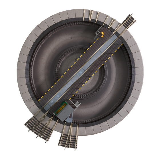
TURNTABLE 6152 C. The FLEISCHMANN Turntable 6152 C was constructed as a built-in turntable. Complete with trench and turning platform this is a true-to-life mo-
del. The turntable is electrically operated and can be operated remotely by the turntable switch 6910, which is included. The switch will fit into the FLEISCHMANN dia-
grammatic control (Fig. 1). Installation: For installing the turntable you will need a hole with 340 mm diameter in your layout board. It will not be necessary to fasten it
down, as the turntable will be stopped at fastened tracks. If the turntable has to be laid on top of the layout, a base of polystyrene (or similar) should be laid under-
neath. In this case entry and exit ramps 30 mm high must be creat ed for the tracks. The turntable is divided into 7.5° sections with a maximum of 48 possible rail con-
nections. The 7.5° sections are provided to match up to the standing position of 3 locos in the loco shed 6476. The turntable can also be set up for 15° section opera-
tion. In this case only one cover plate should be left between the sidings (Fig. 2). The 7.5° track angle of the Turntable 6152 C, is compensated for by fitting a Track
Section 6139. The inner circle track runs parallel to the nearest track. Connecting the motor of the platform: Attention! First connect all of the wires of the turntable and
its switch before you connect the mains transformer to the AC-outlet. Otherwise you risk the damage of the switch caused by short-circuit. The 3 wires, red, yellow and
grey must be connected to the correspond ing wires on the switch, if necessary with the 6941 connector. The black and white wire from the switch must go to the A. C.
connection on the transformer / controller (type 670601, 6725, 6735, 6755/Fig. 3), also for digital operation. Rotating the turntable by hand, see fig. 11 and 12. Con-
necting current to the platform: The twin yellow wires of the turntable should be connected to the clips for the D. C. on the transformer (Fig. 3). If operating the layout
digitally, then the twin yellow wires should not be connected to the digital transformer, but connected to the lilac and lilac/white of the digital controller. Controlling the
connecting track: With this turntable switch the platform can be turned either to the left or right by means of the black switch. The platform stops automatically at
each track. A continuous action through to your chosen position is possible if the switch is pushed into the direction of travel to its outer limit until the position is rea-
ched. On reaching this position, it is stopped by pressing in the opposite direction (Fig. 4). Feeding the connecting track with power: In conjunction with the turntable
switch 6910, each connecting track of this "thinking" turntable can be selected to be fed with power from the turntable bridge (Fig. 5/6). If the turntable switch 6910 is
turned to the position marked
"
"
, then the connecting track which is lined up with the turntable bridge side with the attendant's cab will be fed with power. If the turn-
table switch is turned to the position marked "w", then the connecting track which is lined up with the turntable bridge side without the attendant's cab will be fed with
power. With this "comfort" turntable, then either one or the other track will be fed with power, and never both at the same time. In this way, a loco can be stored on a
track without power, an simultaneously, one located on the track lined up immediately opposite the turntable bridge can still be operated. Operation of the layout with
two, or more, transformers: The turntable area should be controlled by a separate transformer. All lines which go over into the turntable area should be cut off with two
isolating fish plates 6433 (Fig. 7). Operating of the layout with one transformer: It is possible to operate the whole layout with just one transformer. As before all lines
to the turntable area are cut off with two isolating fish plates 6433. Current is fed into the line. The turntable is also fitted with a switch 6904/6924 or a pause switch
6905 (Fig. 8). Extensions: With the Extensions Set 6433 the turntable can be extended to cope with three rail connections (Fig. 9). The turntable should be placed away
from the area of the installed parts. The cover plates are now pulled up by pushing back the spring switch-tongues (Fig. 10), and stuck in the approach track. Every ap-
proach track is to be set up opposite a blind section or another approach track. Rotating the turntable by hand: Opposite the motor housing, under the turning table,
is a small black lever. By pressing the lever towards the centre, the drive gear wheel is withdrawn from the teeth in the outer drive ring releasing the table so that it can
be moved manually in the desired direction. When the lever is released the gear wheel is again enmeshed with the outer-ring. Ensure, however, that the rotating tracks
are lined up with the exit tracks (Fig. 11). Should the turntable not operate, when pressing the switch 6910, simply press the lever slightly to ensure the gear wheel is
firmly seated in the drive ring, which will then start it moving. It will then stop at the next track again (Fig. 12). Oiling the motor: To oil the drive motor both lattice cover
plates must be removed from the machine house with a screwdriver (Fig. 13). Just one drop of oil should be put through the holes to lubricate the points as shown.
Only use FLEISCHMANN-oil 6599. An applicator needle is located in the cap of the oil bottle for your use (Fig. 14). Dismantling the table: Should the turntable not
operate by moving the lever, it will be necessary to dismantle the table. Using a small screwdriver, gently lift the small coverplate in the centre of the table between the
two rails and spring off the circlip on the central pivot (Fig. 15). Be careful not to lose the circlip! On each side of the platform take off 6 opposing components (Fig. 10).
Now the platform can be removed. The contact points and springs round the central pivot should be cleaned. To put the table back together simply reverse the proce-
dure. In the unfortunate instance that the turntable should still not function, please return it to your local dealer or to your supplier or direct to the FLEISCHMANN Tech-
nical Centre.
We reserve all rights to carry out alterations and improvements of all models or items.
PLAQUE TOURNANTE 6152 C. La plaque tournante FLEISCHMANN 6152 C a été réalisée comme élément à encastrer. La fosse et le pont sont absolument confor-
mes au grand prototype. La plaque tournante est actionnée par un moteur électrique ; elle est livrée avec un poste de commande 6910 spécialement conçu pour la télé-
commande. Ce poste de commande s'adapte au système FLEISCHMANN de poste de commande figuratif (fig. 1). Montage : Pour le montage de la plaque tournante il
faut prévoir dans la table du réseau un trou de 340 mm Ø. On la dépose dans ce logement. Il n'est pas nécessaire de la fixer au moyen de vis car les rails d'accés, qui
sont eux-mêmes fixés, suffisent pour la maintenir en place. Il est possible, dans certains cas, de poser la plaque tournante tout simplement sur la table du réseau. Il
faut alors camoufler le bord de la plaque et également construiere des rampes d'accès de 30 mm de hauteur pour chaque voie d'accès. Le pourtour de la plaque
tournante est partagé en secteurs de 7,5°, ce qui peut procurer un maximum de 48 voies d'accès. La remise à locomotives circulaire 6476 est prévue pour loger 3 loco-
motives côte à côte sur des voies distantes chacune de 7,5°. Les voies d'accès peuvent aussi être placeées à 15° les unes des autres. Il faut alors maintenir un secteur
plein entre chaque voie (fig. 2). La division de la voie de 7,5°, de la plaque tournante 6152 C, est compensée par l'incorporation d'une partie de voie 6139. La voie est
conduite parallèlement vers la voie la plus proche, sur le côté de la courbe intérieure. Courant pour le moteur du pont tournant : Attention ! Connectez tous les
câbles du poste de commande et les câbles de la plaque tournante. Aprés, connectez le transformateur à la prise de courant. Autrement vous risquez le destruction de
la poste de commande par court-circuit ! Le câble triple, comportant les couleurs rouge, jaune et gris, doit être raccordé aux couleurs correspondantes du poste de
commande, en utilisant une plaque à bornes 6941. Le câble bipolaire, noir et blanc, du poste de commande seront raccordé aux bornes de couleur correspondante du
~
transformateur, qui fournissent du courant alternatif
(transformateur/regleur 670601, 6725, 6735, 6755/fig. 3), aussi pour opération digitale. Manœuvre de la
plaque tournante à la main, voir illustrations No. 11 et 12. Courant de traction dans le pont tournant : le câble bipolaire jaune de la plaque tournante est raccordé
aux bornes de couleur correspondante du transformateur, qui fournissent le courant continu = (fig. 3). Multi-commande digitale : le câble bipolaire jaune ne doit pas
être raccordé au trasfo digital, mais on peut raccorder anu câble violet et au câble blanc/violet des postes de la commande digitale. Contrôle des voies d'accès : En
appuyant sur le bouton noir du poste de commande 6910 (soit vers la gouche, soit vers la droite) on provoque la rotation du pont tournant dans la direction correspon-
dante. Le pont s'arrête automatiquement à chaque secteur. Si on désire une rotation continue on doit bloquer le bouton noir à fin de course dans la direction souhaitée.
Dès qu'on arrive à proximité de la voie désirée, il faut évidemment débloquer la bouton noir (fig. 4). Alimentation des voies d'accès : Contrôlée par la commande de
plaque tournante 6910, cette plaque tournante "programmable" permet le choix de l'accès alimenté en courant électrique par le pont mobile. En positionnant la com-
mande de la plaque sur le symbole
"
"
, la voie de sortie se trouvant en regard du côté du pont mobile où se trouve la cabine de contrôle sera mise sous tension. Si
l'on place la commande sur se symbole "w", c'est la voie de sortie située à l'opposé du pont qui sera alimentée. Sur la plaque "Comfort", l'une ou l'autre sortie sera
alimentée en courant, mais jamais les deux ensemble. Cela permet d'amener une loco sur une voie sans tension, tout en rangeant une autre loco sur la voie opposée
par rapport au pont mobile (fig. 5/6). Alimentation du réseau au moyen de 2 ou plusieurs transformateurs : La plaque tournante et les voies en vironnantes doivent
en principe être alimentées par un même transfor mateur. En règle génerale il faut placer 2 éclisses isolantes 6433 dans chaque voie aux approches de la plaque
tournante (fig. 7). Alimentation du réseau au moyen d'un seul transformateur : Il est également possible de n'utiliser qu'un seul transformateur pour l'entièreté du ré-
seau. Toutefois, la régle reste la même : il faut aussi placer 2 éclisses isolantes 6433 dans chaque voie aux approches de la plaque tournante. Le courant de traction est
évidemment envoyé dans les voies du réseau proprement dit, tandis que le courant de traction vers la plaque tournante est fourni à celle-ci par l'intermédiaire d'un in-
verseur 6904/6924 ou d'un inverseur momentané 6905 (fig. 8). Agrandissements : Les possibilités de la plaque tournante peuvent être augmentées en lui adjoignant
un ou plusieurs sets complémentaires 6153. Chacun d'eux fournit ainsi 3 voies d'accès de plus (fig. 9). Il faut d'abord orienter le pont tournant vers des secteurs autres
que ceux qu'on veut modifier. On soulève ensuite les secteurs modifier en eppuyant sur les lamelles de fixation (fig. 10) ; puis on les remplace par des rails d'accès. Il
faut veiller à ce que, en face de chacun de ceux-ci se trouve soit un autre rail d'accès, soit une buttée d'arrêt. Manœuvre de la plaque tournante à la main : En face
de la cabine, sous le tablier du pont tournant, se trouve un levier. Lorsqu'on pousse sur ce levier vers le centre du pont, on dégage l'engrenage d'entrainement et on
peut alors faire pivoter le pont tournant dans le sens désiré. Dès qu'on lache le levier, les engrenages se bloquent à nouveau. Il faut veiller à ce que les voies du pont
correspondent à ce moment avec un rail de sortie (fig. 11). Si, en manœuvrant le poste de commande 6910, le pont ne bougeait pas, il faut alors appuyer légèrement
sur le levier en direction du bord de la plaque tournante afin de réengager les engranages (fig. 12). Graissage du moteur : Pour huiler les coussinets du moteur, il faut
soulever au moyen d'un petit tournevis les deux plaques striées se trouvant devant la cabine (fig. 13). On peut alors laisser couler une petite goutte d'huile aux endroits in-
diques. N'utilisez que l'huile recommandée FLEISCHMANN 6599. L'aiguille montée dans le bouchon du petit flaçon convient parfaitement à cet usage (fig. 14). Démon-
tage du pont tournant : Si après avoir appuyé sur le levier comme il est dit ci-dessus, le pont ne tournait pas encore, il faudrait démonter le pont. Pour celà il faut soule-
ver au moyen d'un petit tournevis la tôle se trouvant entre les rails au centre du pont. Ensuite on enlève l'anneau de fixation (fig. 15). Attention ! Veiller à ne pas perdre
l'anneau de fixation! De chaque côte de la plaque tournante on démonte au moins 6 secteurs se faisant face (fig. 10). Les contacts circulaires et les lamelles de prise de
courant doivent être nettoyés. Le remontage se fait en sens inverse. Au cas où certaines pièces seraient endommagées, il faudrait envoyer la plaque tournante avec son po-
ste de commande 6910 au service répara tions de l'usine ou à l'un de ses distributeurs.
Toutes modifications et droits réservés.
DRAAISCHIJF 6152 C. De FLEISCHMANN draaischijf 6152 C wordt als ingebouwde draaischijf gekonstrueerd. Met gróeven en draaibrug is het grote voorbeeld natuur-
getrouw nagebootst. De draaischijf wordt elektrisch aangedreven en is door de bijgesloten draaischijfschakelaar 6910 op afstand te bedienen. De schakelaar behoort bij
het FLEISCHMANN schakelpaneel (Fig. 1). Inbouw: Voor het inbouwen van de draaischijf wordt in de grondplaat een gat van 340 mm Ø gezaagd, zodat de draaischijf
erin geplaatst kan worden. Het vastschroeven is niet noodzakelijk, omdat de draaischijf boven de te bevestigen oprijrail gehouden wordt. Eventueel kan de draaischijf
ook op de grondplaat geplaatst worden. De draaischijf rand moet dan door vulstukken, bijv. Styropor, bekleed worden. Eveneens moeten 30 mm, hoge opritten voor de
op- en afrijrails gefabriceerd worden. De draaischijf is door de 7,5°-indeling met max. 48 railaansluitingen uitgerust. Bij 7,5°-railindeling is voor lokomotiefloods 6476
3 lokloodsen beschikbaar. De draaischijf kan echter ook vor 15°-indeling gebruikt worden. In dit geval moet het draaiplateau uitgebreiel worden (Fig 2). Motoraanslui-
ting van de brug: Attentie! Eerst alle draaden van de draaischijfschakelaar en de draaischijf aansluiten en pas dan de netstekker van de trafo in het stopcontact ste-
ken. Anders bestaat het gevaar voor kortsluiting in de draaischijfschakelaar! De 3-delige snoeren in de kleuren rood, geel, grijs moeten met de overeenkomstige
snoeren van de schakelaars verbonden worden, b. v. boven de klemplaat 6941. De zwart-witte soutache van de schakelaar moet met dezelfde kleur van wisselstroo-
maansluiting ~ van de trafo's / rijregelaar's verbonden worden (Typen 670601, 6725, 6735, 6755/Fig. 3), ook voor digitaal bedrijf. Bediening van de draaischijf met de
hand zie fig. 11 en 12. Rijstroomaansluiting van de brug. Het gele dubbesnoer van de draaischijf wordt aan dezelfde kleur klemmen van de gelijkstroomaansluiting =
aan de regel-transformator aangesloten (Fig. 3). In geval van digitaal bedrijf van de modelspoorweg mogen beide gele draden niet met de digitale trafo, maar uitsluitend
met de lila en de lila/witte draden van het digitale regelapparaat worden verbonden. Sturen van de aansluitsporen: Met de draaischijfschakelaar kan door de bewe-
ging van de zwarte schakelaar, naar rechts of links, de draaibrug in de juiste richting in bedrijf worden gesteld. De draaibrug stopt automatisch bij elk deelstuk. Een ge-
kontinueerd doorijden naar de gewenste positie is mogelijk, wanneer de schakelaar naar de keuze van draairichting door het naar buiten trekken ingesteld wordt. Bij het
bereiken van de gewenste positie moet de instelling door het drukken in de tegenovergestelde richting weer losgemaakt worden (Fig. 4). Stroomtoevoer van de aans-
luitsporen: Via de draaibrug worden de opstelsporen van stroom voorzien. Wanneer men de draaischijfschakelaar 6910 op het symbool
aansluitspoor stroom, dat met de draaibrugzijde met het bedieningshuisje in verbinding staat. Wanneer de draaischijfschakelaar op het symbool "w" staat, dan krijgt
dat aansluitspoor stroom, dat met de draaibrugzijde zonder bedieningshuisje in verbinding staat. Bij de "Comfort"-draaischijf wordt of het ene of het andere spoor van
stroom voorziaen, maar nooit beide tegelijk. Hierdoor kan een loc op het ene spoor stroomloos staan, terwijl op het tegenoverliggende spoor (dus via de draaibrug met
elkaar verbonden) met een andere loc gerangeerd kan worden (Fig. 5/6). Werking van de installatie met 2 of meer regeltransformatoren: Het draaischijfbereik moet
met een apparaate regel-transformator uitgevoerd worden. In principe zijn alle rails bij de overgang van het draaischijfbereik tot de installatie door het inbouwen van 2
isolatie-railverbindingen 6433 elektrisch te scheiden (Fig. 7). Werking van de installatie met 1 regel-transformator: Het is ook mogelijk, de totale installatie met een
trafo uit te voeren. Ook hier zijn alle rails bij de overgang van het draaischijfbereik tot de installatie door 2 isolatie-railverbindingen 6433 elektrisch te scheiden. De instal-
latie wordt met rijspanning gevoed. De draaischijfbrug word aan sluitend over een ompoolschakelaar 6904/6924 of moment-ompoolschakelaar 6905 gevoed (Fig. 8).
Uitbreiting: Met de uitbreidingsset 6153 kan de draaischijf met telkens 3 railaansluitingen uitgebreid worden (Fig. 9). De draaischijf is buiten het bereik van de in te bou-
wen deelstukken te brengen. Nu kunnen de afdekplaten door het terugdrukken van de verende tongen (Fig. 10) naar boven eruit getrokken worden en op de oprijrails
geplaatst worden. Elke oprijrail is tegenover een stootblok of weer op een oprijrail te plaatsen. Handbediening van de draaischijf: Tegenover het machinehuis is onder
de draaischijf bij de aandrijving een hefboom aangebracht. Door drukken op de hefboom en deze gelijktijdig in de richting van de draaischijf te houden, komt het aan-
drijfwiel uit de verlanding van de draaikuil, zodat de draaischijf in elke gewenste richting versteld kan worden. Na het loslaten van de hefboom komt het aandrijfwiel
weer in de vertanding van de draaikuil. Er moet op gelet worden dat de railaansluiting van de draaischijf gelijk komt aan te sluiten rail (Fig. 11). Zou ondanks bediening
van de schakelaar 6910 de aandrijving klemmen of niet lopen, dan kan door even de hefboom in de richting van de draaikuilrand te drukken de draaischijf in bedrijf ge-
zet worden. Deze gaat dan na de volgende rail aansluiting weer stil staan (Fig. 12). Het oliën van de motor: Om de lagers vande aandrijfmotor te kunnen oliën, moeten
de beide roosters van het machinehuis met een kleine schroevendraaier weggenomen worden (Fig. 13). Door de gekenmerkte gaten moet één druppel olie op de ge-
merkte lagers worden toegevoegd. Alleen FLEISCHMANN-olie 6599 gebruiken. Voor een juiste dosering het spuitje gebruiken dat wordt bijgelevered in het olief lesjes
(Fig. 14). Demonteering van de draaibrug: Loopt de draaischijf ook na gebruik van de hefboom niet, dan moet deze gedemonteerd worden. Daarvoor wordt een kleine
schroevendraaier het middelste rooster tussen de rails en de draaibrug weggenomen en de borgring van de draaipen weggenomen (Fig. 15). Voorzichtig! Borgring niet
verliezen! Op elke zijde van de draaischijf worden minstens 6 tegenoverliggende delen verwijderd (Fig. 10). Nu kan de brug in deze uitvoering geplaatst en eruit genom
worden. De kontakten naast de draaipen en de veerkontakten moeten gereinigd worden. De inbouw van de draaischijf geschiedt in tegenovergestelde richting. Kan
men de draaischijf zelf niet herstellen dan moet men deze door de FLEISCHMANN dealer laten reparen.
Verandering, zowel rechten en eventuele modelverbeteringen bij alle artikelen zijn voorbehouden.
PIATTAFORMA GIREvOLE 6152 C. La piattaforma 6152 C è stata progettata per l'esercizio alla quota del piano dei binari, quindi per montaggio incassato. Si tratta di
una fedele riproduzione del prototipo in uso presso le ferrovie di vari Paesi. Il suo funzionamento è elettrico ed è manovrata a distanza mediante l'apposito interruttore
6910, che a sua volta fa parte del posto di manovra figurativo FLEISCHMANN (fig. 1). Montaggio (fig. 2): Nel basamento, in corrispondenza del punto prescelto
dell'impianto, si pratica un foro del Ø di 340 mm; foro nel quale la piattaforma verrà incassata, ma non fissata, essendo tenuta ferma dai raccordi di binari, i quali devono
però venire avvitati. Nei casi in cui non si volesse o non si potesse incassare la piattaforma, la medesima quò venire sistemata sul basamento, appoggiandone la coro-
na su di un materiale di riempimento e contemporaneamente munire i binare di accesso di una rampa di 30 mm. La piattaforma è suddivisa in settori da 7,5°, consen-
tendo così un massimo di 48 binari di raccordo. Il deposito locomotive 6476 è praticabile da 3 locomotive su binari affiancati a 7,5° l'uno dall'altro. Volendo, i binari di
accesso possono trovarsi a 15°; basta in questo caso coprire il binario di mezzo. La divisione del binario di 7,5° della piattaforma rotante 6152 C viene compensata
mediante l'incorporazione di un pezzo di binario 6139. Al lato dell'arco interno il binario viene condotto parallelamente rispetto al binario disposto immediatamente
accanto. Motore elettrico del ponte girevole (fig. 3): Attenzione! Dapprima lei collega tutti i fili della piattaforma girevole ed il suo interruttore prima che lei collega il
trasformatore principale alla CA-presa. Altrimenti rischiate danni dell'interruttore causato dal cortocircuito. l cavetto a tre conduttori (rosso, gialla e grigio) è da collegar-
si a quello dell'interruttore nei rispettivi colori, mediante, il morsetto 6941. Il cavetto bipolare (nero e bianco) dell'interruttore è da collegarsi ai morsetti a corrente alter-
~
nata
aventi uguali colori del trasformatore (trasformatori tipo 670601, 6725, 6735, 6755), anche per operazione digitale. Per la manovra a mano della piattaforma
vedi la fig. 11 e 12. Corrente di trazione del ponte girevole (fig. 3): Il cavetto con ambedue i fili gialli della piattaforma è da collegarsi ai morsetti di uguale colore del
tras formatore che fornisce corrente continua. Utilizzando il comando multireno digitale FLEISCHMANN il cavetto con ambedu i fili gialli non deve essere collegato al
trasformatore digitale, ma deve essere collegato al filo violette ed al filo violetto/bianco dei dispositivi di comando digitale. Timone dei binari di collegamento (fig. 4):
La piattaforma viene messa in moto da un motorino nella rotazione destrorsa a sinistrorsa, ossia manovrando a destra o a sinistra il tasto nero dell'apposito interruttore.
La parte girevole si fermerà automaticamente ad ogni successivo settore, nel caso però la si volesse bloccare su di un determinato settore, sarà necessario fissare il
nottolino di arresto del tasto su tale settore, sbloccandolo poi appena arrivata a raccordarsi col binario prescelto. Alimentazione elettrica dei binari di collegamento
(fig. 5/6). Con il selettore 6910 per la manovra della piattaforma girevole si può, con questa piattaforma "pensante", selezinare anche il binario di collega mento che verrà
alimentato dalla stessa piattaforma. I binari di deposito vengono alimentati dalla piattaforma. Posizionando il selettore 6910 sul simbolo
collegato alla piattaforma lato garitta. Posizionando il selettore sul simbolo "w", viene alimentato il binario collegato alla piattaforma sul lato opposto alla garitta. Con
la piattaforma modello "Comfort" viene alimentato l'uno o l'altro dei due binari, ma mai entrambi contemporaneamente. Questa modalità consente di depositare una
locomotiva senza corrente su un binario, mentre contemporameamente si può manovrare un'altra locomotiva sul binario esattamente opposto, collegato attraverso la
piattaforma. Esercizio con due o più trasformatori: E' consigliabile che la piattaforma venga posta in funzione con un proprio trasformatore, tra l'altro è buona norma
inserire due segmenti isolanti 6433 nei binari che vanno alla piattaforma (fig. 7). Esercizio con un trasformatore: L'impinanto in questione può pure funzionare con un
solo trasformatore. Anche in questo caso è però necessario isolare elettricamente la piattaforma dai binari di raccordo inserendovi due segmenti isolanti 6433. La cor-
rente di trazione viene così immessa nell'impianto, mentre la piattaforma riceve la corrente di trazione attraverso l'invertitore 6904/6924, oppure quello 6905 (fig. 8).
Ampliamento: L'impiego della piatta forma quò venire ampliato di tre raccordi di binari per ogni set complementare 6153 (fig. 9). Per prima cosa il ponte girevole è da
orientarsi verso i settori non interessati all'ampliamento. Si levano poi i lamierini di copertura dei settori da modificare premendo all'indietro le lamelle di fissaggio (fig.
10), sostituendo infine con binari di accesso. A fronte di ogni binario di accesso è da montarsi un traversone di arresto oppure un altro di accesso. Manovra a mano
della piattaforma: Dirimpetto la cabina è montata una levetta a mano. Premendo e nello stesso tempo trattenendo la levetta nella direzione mediana della piattaforma,
la sua parte mobile potrà rotare nella direzione desiderata. Abbandonando la levetta, la parte mobile tornerà a bloccarsi. Si farà attenzione a che il binario di raccordo
corrisponda essattamente con quello prescelto sulla piattaforma (fig. 11). Nel caso che manovrando l'interruttore 6910 non si avesse il funzionamento della piattoforma,
occorrerà premere per breve tempo la levetta a mano, appunto per far rotare il ponte (fig. 12). Lubrificazione del motore: Per oliare il motore occorre togliere le due
piastrine a griglia della cabina svitandone le viti di fissaggio (fig. 13). Lubrificare solo nei punti indicati, è sufficiente una sola goccia d'olio (non alimentare) per ogni punto
da lubrificare. Utilizzare solo olio FLEISCHMANN 6599. Per il dosaggio utilizzare l'ago di cui è provvisto il tappo di chiusura del flacone dell'olio (fig. 14). Demontaggio
della piattaforma: Se anche con detta manovra il ponte non gira, bisognerà allora smontario. Con un piccolo cacciavite svitare la piastrina striata che si trova tra i
binari del ponte, togliendo pure la ranella di tenuta al perno (fig. 15). Si farà attenzione a che non vada perso tale anello. Da ogni parte della piattaforma si smontino
almeno sei settori frontali (fig. 10). Puliti contatti e perni, si rimetterà la piattaforma in funzione. Però, nell'eventualità di mancato funzionamento, oppure ci fosse qualco-
sa di rotto, consigliamo di portare al rivenditore di fiducia piattaforma e interruttore 6910.
Riservati tutti diritti, comprese eventuali varianti.
Gebrauchsanweisung aufbewahren!
Retain Operating instruction!
per l'uso!
¡Conserve instrucciones de servicio!
GEBR. FLEISCHMANN GMBH & CO. KG
D-91560 Heilsbronn, Germany
www.fleischmann.de
"
"
23.1 A
zet, dan krijgt alleen dat
"
"
viene alimentato il binario
Gardez l'instruction de service!
Gebruiksaanwijzing bewaren!
Gem vejledning!
Ritenere l'istruzioni
14 v
/16 v
21/6152-0103
BETRIEBSANLEITUNG
Operating Instruction • Instructions
de service • Handleiding • Vejled-
ning • Istruzioni per la manutenzione
Drehscheibe
6152 C
Fig. 1 Die FLEISCHMANN-Drehscheibe 6152 C wurde als Einbau-Drehscheibe konstruiert. Mit Grube und Drehbühne ist das große Vorbild
modellgetreu nachgebildet. Die Drehscheibe ist elektrisch angetrieben und über den beiliegenden Drehscheiben schalter 6910 fernsteuerbar.
Der Schalter paßt zum FLEISCHMANN-Gleisbildstellwerk.
Fig. 2 Zum Einbau der Drehscheibe wird in die Anlagenplatte ein Loch von 340 mm Ø gesägt, in das die Drehscheibe eingesetzt wird. Ein
Fest schrau ben ist nicht erforderlich, da die Drehscheibe über die zu befestigenden Zufahrtsgleise gehalten wird.
Führen Gleise unterhalb der Drehscheibe vorbei, (z. B. verdeckter Abstellbahnhof), so ist auf eine genügende Durchfahrthöhe zu
achten, da die Dreh scheibengrube eine Tiefe von 25 mm besitzt. Um ein Entgleisen von Zügen oder Loks zu vermeiden, dürfen die An-
schlußkabel nicht frei herabhängen, sondern müssen sauber verlegt werden.
Gegebenenfalls kann die Drehscheibe auch auf die Anlagenplatte aufgesetzt werden, der Drehscheibenrand muß dann durch
Füllstücke (z. B. Styro por) unterlegt werden. Ebenfalls müssen 30 mm hohe Auffahrtsrampen für die Zu- und Abfahrtsgleise geschaffen
werden.
Die Drehscheibe ist durch die 7,5°-Teilung mit max. 48 Gleisanschlüssen bestückbar. Hierzu ist der dreiständige Ringlokschuppen 6476 vor-
gesehen, der auch mehrteilig ausgebaut werden kann.
Der Lokschuppen 6476 ist vom Auffahrsegment der Drehscheibe im Abstand von 200 mm aufzustellen. Pro Lokstand werden ca.
Einbau
305 mm Gleis benötigt. Diese werden
durch die vorderen Tore eingeschoben
und
von
den
Halteklammern
der
Grundplatte gehalten. Die einzelnen
Gleise werden in Richtung Dreh-
scheibe etwas herausgezogen und mit
je einem Auffahrsegment zusammen-
gesteckt.
Die 7,5°-Gleisteilung der Drehscheibe
6152 C wird durch Einbau eines Gleis-
stückes 6139 ausgeglichen. Auf der
Seite des Innenbogens wird das Gleis
parallel zum nächstliegenden Gleis ge-
führt.
Die Drehscheibe kann aber auch für
15°-Teilung Verwendung finden. In
diesem Fall ist zwischen den einzelnen
Abstellgleisen jeweils 1 Abdeckplatte
zu belassen.

Verwandte Anleitungen für FLEISCHMANN 6152 C


Inhaltszusammenfassung für FLEISCHMANN 6152 C
- Seite 1 6433 elektrisch te scheiden (Fig. 7). Werking van de installatie met 1 regel-transformator: Het is ook mogelijk, de totale installatie met een tion. In this case only one cover plate should be left between the sidings (Fig. 2). The 7.5° track angle of the Turntable 6152 C, is compensated for by fitting a Track trafo uit te voeren.
- Seite 2 Schraubenzieher abgehoben werden. geben. Vorsicht, nicht überölen! Seite der Drehbühne mit Strom versorgt wird. Nur FLEISCHMANN-Öl 6599 verwenden. Zur Dosierung die in der Verschluss- Stellt man den Drehscheibenschalter 6910 auf das kappe der Ölflasche angebrachte Nadel Symbol „...