Herunterladen Diese Seite drucken
krick Victoria Anleitung

krick Victoria Anleitung

Dampfbarkasse massstab 1:12

Werbung

Verfügbare Sprachen

Verfügbare Sprachen

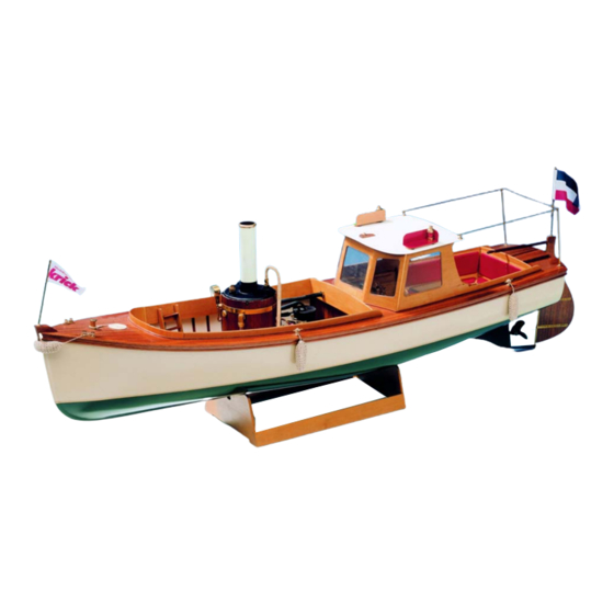
1912 wurde das Vorbild unseres Modells von der engli-
schen Werft Simson, Strickland & Co. gebaut. Es war zur
damaligen Zeit "in" ein Dampfboot zu haben, sei es als
Privatjacht oder als Arbeitsboot. Man legte großen Wert
darauf, dass die kostbare Dampfmaschine für alle sich-
tbar im Schiff platziert war. Im Anfang des 20. Jahrhun-
derts war ja die Dampfmaschine "die" Antriebskraft
schlechthin.
In unserer modernen, schnelllebigen Zeit der Computer
und der Elektronik erinnert man sich gern der sogenann-
ten "guten alten Zeit', und so wird unser Modell Victoria
sicherlich viele Freunde finden.
Um Ihnen die etwas schwierige Arbeit der Herstellung des
Schiffsrumpfes zu erleichtern, haben wir dem Baukasten
einen Fertigrumpf aus schlagfestem ABS-Kunststoff bei-
gelegt. Die Aufbauten aus Edelhölzern sind komplett mit
Dampfbarkasse „Victoria"
Maßstab 1 : 12
Bestell-Nr. 20261
Seite 1
Laser ausgeschnitten, die Beschlagteile (Fittings) sind
aus Metall und liegen dem Baukasten bei. Zur besseren
Ausstattung kann Ihnen ein Ausstattungssatz geliefert
werden, der unter der Bestell-Nr. 20263 erhältlich ist. Bitte
beachten Sie die Hinweise am Ende der Stückliste.
Für die Victoria empfehlen wir die Dampfmaschinen
Victor mit stehendem Kessel.
Dampfmaschine Victor vertikal
Best.-Nr. 22302
Diese oszillierenden Dampfmaschinen sind aus einer
langjährigen
Erfahrung
Dampfmaschinenantrieben entstanden. Diese Erfahr-
ung hat es uns ermöglicht die ideale Kombination aus
originalgetreuer Optik, absoluter Zuverlässigkeit, hoher
© Krick Modelltechnik Knittlingen November 2014
im
Schiffsmodellbau
mit

Werbung

loading

Inhaltszusammenfassung für krick Victoria

  • Seite 1 In unserer modernen, schnelllebigen Zeit der Computer Dampfmaschine Victor vertikal und der Elektronik erinnert man sich gern der sogenann- Best.-Nr. 22302 ten "guten alten Zeit', und so wird unser Modell Victoria Diese oszillierenden Dampfmaschinen sind aus einer sicherlich viele Freunde finden. langjährigen...
  • Seite 2 Außerdem benötigen Sie noch eine Doppelgelenk- Kupplung zwischen Schiffswelle und Dampfmaschine. 1x Gelenkkupplung 4 auf 4 mm Bestell-Nr. 63704 1x Doppelverbinder Bestell-Nr. 63510 1x Kupplungseinheit einzeln Bestell-Nr. 63500 Weiters Zubehör für Dampfmaschinen: Siehe letzte Seite Seite 2 © Krick Modelltechnik Knittlingen November 2014...
  • Seite 3 Auflageleiste am Heck Nr. 3 ca. 10 Minuten in heißes Wasser legen. Während dieser Zeit zeichnen Sie an der Rumpf- innenseite 3 mm von der Schnittkante entfernt ei- Seite 3 © Krick Modelltechnik Knittlingen November 2014...
  • Seite 4 Tesakrepp nach Abb. E fixieren und zum Ab- lüften des Klebers den Rumpf mit dem Deck nach unten auf die Werkbank legen, damit überflüs- siger Kleber nicht an der Bordwand herunterläuft. Seite 4 © Krick Modelltechnik Knittlingen November 2014...
  • Seite 5 Rahmen von unten an den Boden 52 geleimt. Für die nächsten Arbeitsgänge benötigen Sie die Dampfmaschine. Dampfmaschine Victoria (Bestell-Nr. 20262): Für Dampfmaschine Puffin sehen Sie bitte am Ende der Baubeschreibung nach. Zum Einbau von Maschinenraumboden, Stevenrohr, Welle usw. packen Sie sie aus und legen sie auf den Bauplan.
  • Seite 6 Das Ruder 75 liegt fertig ausgeschnitten dem Bau- kasten bei. Lediglich ein Schlitz von 4 mm Breite muss 10 mm unterhalb der Oberkante ausgesägt werden (Abb. J). Beplanken Sie das Ruder nach Seite 6 © Krick Modelltechnik Knittlingen November 2014...
  • Seite 7 An den Befestigungsklotz 120 für die Rudermaschine werden die beiden Werkzeugschranksei- tenteile 119 angeklebt. Anschließend werden in die beiden Klötze die Löcher 3 mm für die Be- festigungsschrauben 121 gebohrt und die am Kopf versenkten Schrauben eingeklebt. Seite 7 © Krick Modelltechnik Knittlingen November 2014...
  • Seite 8 163 Lampenpodest, 164 Stangenkopf, 165 Lampenoberteil, 166 Glas, 167 Lampenunterteil, 168 Schirm an, wo- bei Sie bitte beachten, dass in den Lampenfuß 160 der Haltestift 161 als Verstärkung eingeklebt werden muss. Um die Seite 8 © Krick Modelltechnik Knittlingen November 2014...
  • Seite 9 22111: Abdampfführung. Ihr Modell ist jetzt fertig. Sie müssen nur noch Ihr Modell austrimmen. Bitte beachten Sie alle Vorsichtsregeln, die Sie in der Anleitung zur Dampfmaschine finden. Zum Austrimmen Ihrer Victoria benötigen Sie zusätzlich: 3x Packungen Ballast Bestellnr. 60102, 1x Packung UHU plus endfest Bestellnr.
  • Seite 10 Lage der Dampfmaschine ausgerichtet haben, schrauben Sie sie am Maschinenboden mit den Schrauben 218 fest. Entfernen Sie den Anschlagstift für den Umlenkhebel an der Dampfmaschine, falls vorhanden. Der Umlenkhebel wird um 180 Grad gedreht. Klaus Krick Modelltechnik Industriestr.1 75438 Knittlingen Telefon: (07043) 93510 Fax: (07043) 31838 Seite 10 © Krick Modelltechnik Knittlingen November 2014...
  • Seite 11 Kiefer 3x3x70 mm Bodenspant 48-50 Sperrholz 3 mm Halteleiste Kiefer 5x5x320 mm Maschinenraumboden Sperrholz 3 mm Einfassung 53-54 Sperrholz 3 mm Bodenplatte Sperrholz 3 mm Ausgleichsplatte Sperrholz 3 mm Welle m. Schraube Fertigteil Seite 11 © Krick Modelltechnik Knittlingen November 2014...
  • Seite 12 Sperrholz 3 mm Formstück Sperrholz 3 mm Dachbalken Sperrholz 3 mm Fensterfrontteil Sperrholz 3 mm Fensterfrontteil Sperrholz 3 mm Fensterleiste Mahagoni 1x1x1200 mm ges. Rückenblende Sperrholz 3 mm Seitenteil Sperrholz 3 mm Seite 12 © Krick Modelltechnik Knittlingen November 2014...
  • Seite 13 Ms-Fertigteil Haltestift Ms-Draht 2x25 mm Lampenstange Ms-Rohr 3x0,45x100 mm Lampenpodest Sperrholz 1,5 mm Stangenkopf Ms-Fertigteil Lampenoberteil Ms-Fertigteil Glas (klar) Kunststoff-Fertigteil Lampenunterteil Ms-Fertigteil Schirm ABS-Rest Positionslampenteil Sperrholz 1,5 mm Positionslampenteil Sperrholz 1,5 mm Seite 13 © Krick Modelltechnik Knittlingen November 2014...
  • Seite 14 Die mit einem „ # “ versehenen Positionen werden zum Einbau einer Dampfmaschine benötigt. Die mit einem „ * “ versehenen Positionen sind Bestandteil im Victoria Ausstattungssatz Bestell-Nr. 20263 Die mit einem „ + “ versehenen Positionen sind separat unter den Bestell-Nr. 63705 bzw. 63704 + 63510 + 63500 erhältlich.
  • Seite 15 Seite 15 © Krick Modelltechnik Knittlingen November 2014...
  • Seite 16 Seite 16 © Krick Modelltechnik Knittlingen November 2014...
  • Seite 17 Aus unserem Dampfmaschinensortiment empfehlen wir die nachstehend aufgeführten Ergänzungsteile. Best.-Nr. 22313 Gastank mit Ablaßventil Best.-Nr. 60105: Krick Gascontainer 800 ml Gaskartusche zum umfüllen in den Gastank mit genormten Gewinde. Das Flüssiggas besteht zu 70 % aus Butan zu 30 % aus Propan.
  • Seite 18 Modellbau vom Besten   krick Victoria • 20261  Klaus Krick Modelltechnik Victoria Building Instructions The prototype of this model was built in 1912 by the shipyards of Messre. Simson, Strickland & Co. At that time  it was very fashionable to have a steam launch, either as a private yacht or as a transport-vessel. lt was of great  importance to have the valuable steamengines at an exposed position, visible for everybody, as at the beginning  of the 20th century the steamengine was the motive power par excellence.  In our „modern“ giddy-paced time of electronics and computers one likes to remember the „good old times“, and  so we presume that our model of the „Victoria“ will make many friends. To save you the rather complicated construction of a wooden hull, our kit is based on a hull vacuum moulded  of high impact ABS. The majority of the superstructure components are laser cut of high grade woods and the  fittings, thoroughly made of metal, are supplied with the kit. For better appearance we can deliver a de luxe equipment set (no. 20263) with fenders, bollards, flags, sun struts  and a boatswain. Please take notice of hints behind the parts list.
  • Seite 19 Victoria • Steam Launch 20261 Recommended accessories   1 x Set of equipment for Victoria, Order No. 20 263   3 x dietary iron shot, Order No. 60 112   Also, you still need a clutch shaft between the ship and steam engine.   1 x Articulated coupling 4 to 4 mm Order no. 63 704   1 x Double Joint Order no. 63 510   1 x Coupling unit individually Order no. 63 500     1x articulated coupling 4 to 5 mm Order no. 63 705   1x Double Joint Order no. 63 510   1x coupling unit individually Order no. 63 500 All parts are numbered for easy identification on the plan and listed in numerical order in the parts list. Carefully  follow instructions and always use glues and cements as specified. All materials and accessories required, which are not supplied with the kit, are mentioned at the end of the parts  list.   We wish you lots of pleasure with your „Victoria“ and always a hand‘s breadth of water under her keel. Technical data:     Scale:    1:10   ...
  • Seite 20 Victoria • Steam Launch 20261 Make a sanding block of about 50x300 mm, fix 100 grit sandpaper to it and sand hull edges as shown in Fig. C. Get  out  from  Plywood  7  mm  the  part  68.  Cut  carefully  the small narrows in the ply and plane the edges. Do this  with all wood parts. Place part 68 on the keel as shown  in side-view and mark hole for stern tube on the hull. Drill  a 5 mm dia. hole first, then open it up with a round file to  7 mm dia., so that the fillet fits snugly between hull bottom  and stern tube. Soak  deck  support  strips  2  and  3  in  hot  water,  take  a  pencil and draw a line 3 mm below the upper hull edge  around  the  inside  ofthe  hull  to  mark  the  position  of  the ...
  • Seite 21 Victoria • Steam Launch 20261 Splice rubbing strakes 19 and 23 as well  as  spacers  21  from  two  parts  each  as  shown in Fig. G, let dry and then cement  upper running strakes, spacers and lower  rubbing strakes around the top of the hull  as per Fig. D. Cut  and  sand  bow  block  25  to  shape,  drill a 4 mm dia. hole for flagstaff holder  27  and  cement  block  in  position,  then  cut, fit and cement capstrip 26. Make cle- at from parts 28 and 29 but don‘t cement  it in position until all parts have been pri- med and painted. Fit and cement hatch coamings 30 into the hatch near the stern and let them protrude 3 mm, then fit and cement head ledges 31 in position.
  • Seite 22 Victoria • Steam Launch 20261 Press all parts tightly in position and fix engine base plate 55 to frames 53 and 54 with some spots of CA-cement. Remove engine and engine room floor 52 once more, reinforce engine base plate 55 with supports 59 and eventu- ally cement base plate 55 to frames 53 and 54 as shown in Fig. Hand file notches for supports 59 into frame 50. Place engine room floor into the hull again, add doubler 56, steam-engine,  stern tube, and shaft once more, align and then mark the position of the moun- ting holes of the steam-engine on base plate 55. Then  drill  all  required  holes  through  engine  room  floor  52  and  base  plate  55 as shown in reduced scale diecut sheet drawing, press captive nuts 60  through 62 in position from the bottom and secure them with epoxy cement. Cement hatch supports 63 and 64 on the bottom of engine room floor 52 and then fit hatch 65. Put floor into hull  again and mark positions of captive nuts 61 on spacers 51. Cut out spacers about 1,5 mm for captive nuts until floor  52 evenly touches all floor frames and spacers. Then cut, fit and glue planks 66 onto floor. Let dry thoroughly, sand even and then drill mounting holes through the planking too. Prime floor twice all around with sanding sealer and then apply two or three coats of clear varnish or synthetic  enamel.  Scratch waterproofing off floor 52 where it touches frames and spacers. Run beads of white glue on floor supports  37 and 43, spacer supports 46, floor frames 48 through 50 and spacers 51, slide floor 52 into hull tightly against  the fore frame, press the main frame against the rear edge and weigh the floor down until the glue has dried. Then  cement the floor sides and the main frame to the hull with CA-cement. Cement  doubler  56  onto  base  plate  55  and  let  dry.  Then  mount  steam-engine  in  position.  Slide  stern  tube  with ...
  • Seite 23 Victoria • Steam Launch 20261 white glue and jam them in position once more until dry. Then round off upper edges of all bulwarks 95 through 97  and cement them to the deck and to each other as shown in top- and side-view. Fit cockpit floor 98 into the hull and bevel sides as necessary as shown in diecut sheet drawing 2. Cement hatch  supports 99 and 100 unter the bottom of cockpit floor 98 and then fit floor hatches 101. Cut, fit and cement plan king 102 onto floor and hatches, let dry, sand even, waterproof and eventually add eye  bolts 104 with rings 105. Then cement floor onto supports 44 and into hull. Bevel front and sides of wheel-house braces 106 and 108 as per  side-view, then cement bottom brace 106 in position. Sand rear  edge flush with deck 8. Put wheel-house side walls 107 into cock- pit and jam them in position with several braces made of scrap  strip  as  shown  in  Fig.  K.  Cement  top  brace  108  against  roof  beam 1 09 with CA-cement and then fit and cement assembly  between side walls 107, adjusting the braces as necessary. Then  cement side walls to the deck and add rear roof beam 110.  Put front walls 111 and 112 on a smooth surface protected with  waxed  paper  or  some  household  wrap  and  then  cut,  fit  and ...
  • Seite 24 Victoria • Steam Launch 20261 Assemble the rear stern tube cover from parts 131 and 132, bevel it as necessary, waterproof it and cement it in  position. Sand and waterproof bench supports 133 and cement them to cockpit floor 98 and cockpit side walls. Cement rear bench seat supports 137 under side bench seats 136 as shown in top-view, then fit, sand and water- proof parts 134 through 142 as per parts list and fit, sand and paint with red enamel (as red leather imitation) seat  paddings 143 through 146. Now assemble and cement in position both side benches from parts 134 through 138, rear bench support 139 and  seat paddings 143 and 144. Then assemble rear bench from seat 141, back rest 140, support 142 and paddings 145 and 146, but do not ce- ment this assembly into the cockpit, as it is to serve as RC compartment hatch. The assembly and installation of the table from parts 147 through 150 can be clearly seen both in side- and top-view  and should need no further comment. Assembly, waterproofing and installation of engine room bench from seat 151 and support 152 and of the ladder  from spars 153, step supports 154 and steps 155 is selfexplanatory as well. Now remove window panes from the diecut sheet, fit them into their respective window apertures and cut and fit  window frames from cable 157 as well. Before carrying on, please note that any rubbing can cause the window panes to charge themselves with static  electricity, which in turn might cause the CA-cement not to stay, where. you put it, but to spray all over the panes.  Therefore wash the panes in a mixture of water and some household cleanser and let them dry on a clean cloth  without any rubbing whatsoever Then put the boat in a position with the respective window aperture horizontally, put pane and frame in position and  cement with as tiny as possible droplets of CA-cement, applied with the point of a·needle, as shown in Fig. N. Do not  apply the cement directly from its tube, flask or bottle, as any nozzle will be much too large for this delicate task.  Round off the edges of wheel-house roof 158, waterproof  it, add one coat of white enamel to its top side and let dry  thoroughly. Then carefully fit it to the wheel-house, sanding  down any protruding parts of its structure and then cement  the roof in position with thick CA-cement. Carve, drill, sand, waterproof and cement in position lamp- staff holder base 159. Then assemble lampstaffwith lamp  from  lampstaff  holder  160,  mounting  pin  161,  lampstaff ...
  • Seite 25 Victoria • Steam Launch 20261 Now make two twin bitts from bitts 187 and base plates 188 and then cement single bitt 186 and twin bitts onto the  back. Then make four cross bitts from parts 189 and 190 and cement them in position as shown in top-view. Assemble fore flagstaff from mounting pin 191, flagstaff 192, eyebolt 193, top 194, halyard 201 and flag 199,  and the rear one from parts 195 through 198, 201 and 200 in the same  manner and v cement them into flagstaff holders 27 at the bow and 83  on the rudder top 201. respectively. Assemble  life-belts  from  belts  202,  handling  lines  203  and  woolings  204, paint them white and red and fasten them to hooks 116 inside the  wheel-house. See Fig.O. Eventually add transfers 205 with name and ornaments to the bow and  then your launch is ready for the installation of tank, burner, boiler, steam- engine and RC-equipment. To install the engine, slide set collar 206, fix it with the screw M 3 x 12  mm, put steam engine in position, and bolt the engine onto base plate  Then install tank, burner and boiler and connect them as explained in the separate steam-engine instruction leaflet.  Mount the set collar out of the assembly set of the steam engine with a long screw as stop pin of the prop shaft.  Before mounting the screw put a piece of silicon tube over it for reduction of noice. Eventually install the steam exhaust nipple where the port side is marked „X“ on the side-view and connect it to the  engine with silicone tubing. This is not necessary for installing steam engine Victor.  To install the RC-equipment bolt engine servo, rudder servo and switch in position, wrap receiver and power pack  into some sponge material, plug all parts together and stow receiver and power pack into RC compartment in the  stern. Then connect rudder servo with tiller 76 by adjustable push rod connector 207, circlip 208, set screw 209  and push rod 210, and keep the hole in the stern for the latter as small as possible. Thereafter connect engine servo  with speed-lever of steam-engine by pushrod 212 with clevis 211. Your Victoria is ready now. You must only trim your model. For trimming you need additional 3 sets ballast of steel balls no. 60102 and 1 set epoxi glue with long hardening ...
  • Seite 26: Parts List

    Victoria • Steam Launch 20261 Parts List: No. Description Qty. Material Location 1   Hull ........1   Vacuum Moulded ABS 2  ...
  • Seite 27 Victoria • Steam Launch 20261 No. Description Qty. Material Location 54   Engine Base Plate Frame 2 Plywood 3 mn  ..3    #  55   Engine Base Plate  ......1   Plywood 3 mm  ...
  • Seite 28 Victoria • Steam Launch 20261 No. Description Qty. Material Location 112   Wheel-House Front Wall  ....2   Plywood 3 mm   113   Window Frame Strip  ..... . 20   Mahogany Strip 1x1x1200 total 114  ...
  • Seite 29 Victoria • Steam Launch 20261 No. Description Qty. Material Location 168   Lamp Shade ......1   Scrap ABS 169  ...
  • Seite 30 Victoria • Steam Launch 20261     To build and to operate your „Victoria“ you need the following articles,    which are not supplied with the kit: Thin and thick CA-cement, epoxy-cement, polyester-cement, PVA-white glue, sanding sealer; synthetic  enamel (choose a brand that doesn‘t corrode ABS) in clear, white, red, green and black, cloth for the  awning, lighter gas and RC-equipment with one servo each for rudder and engine-control.  Steam engine „Victor“ with standing boiler which is under item number 22302 sold separately. Victor is an in-line Steam-Plant with oscillating cylinders  and vertical boiler, designed for Steam-Boats like  „Victoria“ or „Borkum“.  Standard Equipment: Completely assembled and painted engine  (10mm dia. bore, 14mm stroke) with control  valve forward and reverse. The Set includes Boiler,  mounted steam engine, Lubricator, 70mm dia.  ceramic burner, watergauge, pressure gauge, safety valve, wood lagging and clamps, and  the pipe work as shown. Technical Data: The steam plant comes with a 95 x 225 mm...
  • Seite 31 Victoria • Steam Launch 20261  Klaus Krick Modelltechnik • Postfach 11  3 8 • D-75  4 34 Knittlingen  Telefon 0 70 43 / 9 35 10 •  Telefax 0 70 43 / 3 18 38 • www.krick-modell.de ...
  • Seite 32 Victoria • Steam Launch 20261...
  • Seite 33 • Historisch• Historic• Historique• Die „Victoria“ ist ein typisches kleines Dampfboot aus der Zeit der Jahrhundertwende. Der Prototyp dieses Mo- dells wurde 1912 von den Werften von Simpson, Strickland und Co Ltd in Brixham gebaut. Damals war es sehr  modern, ein Dampf-Boot zu haben, entweder als private Yacht oder als Transport-Fahrzeug. Es war von großer  Bedeutung, die wertvolle Dampfmaschine an exponierter Stelle, für jeden sichtbar, zu zeigen dass man sich die  Dampfkraft als treibende Kraft par excellence leisten kann. The Victoria is a typical steam launch of the turn of the century.  The prototype of this model was built in 1912  by the shipyards of Simpson, Strickland and Co Ltd. At that time it was very fashionable to have a steam launch,  either as a private yacht or as a transport-vessel. lt was of great importance to have the valuable steam engines  at an exposed position, visible for everybody, as at the beginning of the 20th century the steam engine was the  motive power par excellence. La „Victoria“ est une chaloupe vapeur typique de la fin du 19° siècle. Le prototype de ce modèle devenait cons- truit en 1912 des chantiers navals de Simpson, Strickland und Co Ltd dans Brixham. A l‘époque, c‘était très  moderne avoir un bateau de vapeur, comme le yacht privé ou comme le véhicule de transport. C‘était visible de  la grande importance, la machine de vapeur précieuse au lieu exposé, pour chacun indiquer que l‘on peut se  permettre la force motrice à vapeur comme la force ayant une action diurétique par excellence.  Modellbau vom Besten krick  Klaus Krick Modelltechnik  Inhaber Matthias Krick  Postfach 11  3 8 · D-75  4 34 Knittlingen  Industriestr. 1· D-75  4 38 Knittlingen  Telefon 0 70 43 / 9 35 10  Telefax 0 70 43 / 3 18 38  www.krick-modell.de   Klaus Krick Modelltechnik • Postfach 11  3 8 • D-75  4 34 Knittlingen  Telefon 0 70 43 / 9 35 10 •  Telefax 0 70 43 / 3 18 38 • www.krick-modell.de ...