Werbung
Verfügbare Sprachen
Verfügbare Sprachen
Quicklinks
BFB 75K-002 / 003-...
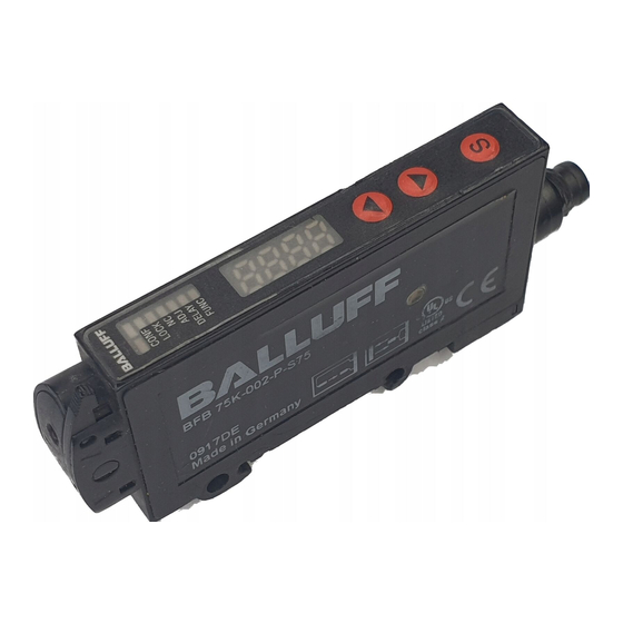
Faserbasisgerät
Fibre base device
Appareil de base pour fibres
- Für Lichtleiter ø2,2 mm
- For fibre optics ø2.2 mm
- DIN Schienen-Montage (DIN-46277-3)
- DIN rail mounting (DIN-46277-3)
- Einfache Bedienung
- Simple operation
- Steuerleitung zur Einstellung oder
- External teach for setting and to disable the teach
Verriegelung
button
- N.O. - N.C. wählbar
- N.O. - N.C. selectable
- Rotlicht 630 nm
- Red light 630 nm
- Display
- Display
- Variante mit zusätzlichem Analogausgang
- Type with additional analogue output
Maßzeichnung / Dimensional drawing / Plan coté
153-00373
153-00372
Optische Daten (typ.)
Optical data (typ.)
Tastweite:
abhängig vom Lichtleiter
Scanning distance:
Standard Mode 150 mm / Fast Mode 70 mm /
Standard Mode 150 mm / Fast Mode 70 mm /
Fine Mode70 mm / High Distance Mode 300 mm
Fine Mode 70 mm / High Distance Mode 300 mm
Betriebsreichweite:
abhängig vom Lichtleiter
Scanning range:
Tastweiteneinstellung:
Teach-in
Sensitivity adjustment:
Bezugsmaterial:
Kodak weiß, 90%, 200x200 mm
Reference material:
Lichtart:
rot 630 nm, gepulst
Used light:
Abstandshysterese (90% / 90%): < 10% der eingestellten
Distance hysteresis (90% / 90%):
Tastweite
Elektrische Daten (typ.)
Electrical data (typ.)
Betriebsspannung +U
:
10 ... 30 V DC
Operating voltage +U
B
Verpolschutz U
:
ja
Reverse battery protection U
B
Steuerleitung (ET/Lock):
+U
= Teach-in Funktion
External teach (ET/Lock):
B
0 V = Teach-in Taste verriegelt
offen = Normalbetrieb
Stromaufnahme (ohne Last):
≤ 25 mA bei 24 V DC
Power consumption (no load):
Schaltausgang:
siehe Auswahltabelle
Signal output:
Ausgangsstrom Ie:
≤ 100 mA
Output current Ie:
Kurzschlussschutz:
ja
Short-circuit protection:
Schaltfrequenz (ti/tp 1:1):
abhängig von der Einstellung
Switching frequency (at ppp 1:1): depends on the setting
Standard Mode 1 kHz / Fast Mode 8 kHz /
Fine Mode 125 Hz / High Distance Mode 125 Hz
Fine Mode 125 Hz / High Distance Mode 125 Hz
Analogausgang nicht skalierbar:
0 - 10 V / 2 mA
Analogue output not scalable:
Anzeigewert 0000:
≙ 0 V
Displayed value 0000:
Anzeigewert 4093:
≙ 10 V
Displayed value 4093:
Schutzklasse:
Protection class:
Schaltausgangsanzeige:
LED gelb
Switching output indicator:
Betriebsspannungsanzeige:
LED grün
Operating voltage
Mechanische Daten (typ.)
Mechanical data (typ.)
Gehäusematerial:
ABS
Casing material:
Schutzart:
IP64
Protection standard:
Umgebungstemperaturbereich:
-20 ... +60 °C
Ambient temperature range:
Lagertemperaturbereich:
-20 ... +80 °C
Storage temperature range:
Anschlusskabel:
5 x 0,14 mm
Cable:
2
Leitungslänge Standard:
2 m
Standard cable length:
Steckeranschluss:
M 8, 4-polig
Connection:
Gewicht (Steckergerät):
ca. 20 g
Weight (plug device):
Gewicht (Kabelgerät):
ca. 50 g
Weight (cable device):
Ausgang
Output
PNP N.O.
Sortie
Anschluss
Stecker
Connection
Connector
Raccordement
Connecteur
Anschlussbild
Wiring diagram
1
Schéma de raccordement
Bestellcode / Typ
BFB0006
Order code / Type
BFB 75K-002-P-S75
Code de commande / Type
Balluff GmbH
D-73765 Neuhausen/Filder, Tel. 07158 173-0, Fax 07158 5010
Montage- und Bedienungsanleitung / Mounting and operating instructions
Empfänger / Receiver / Récepteur
Sender / Transmitter / Emetteur
Klemmbügel / Clamping bracket /
Etrier de serrage
LEDs / LEDs / LEDs
Display / Display / Afficheur
Pfeil-Tasten / Up/down-Button /
Touches de direction
-Taste /
-Button /
- Pour fibres opt. ø2,2 mm
- Montage sur rail DIN (DIN-46277-3)
- Utilisation simplifiée
- Verrouillage et apprentissage déportés électrique-
ment
- N.O. - N.C. réglable
- Lumière rouge 630 nm
- Afficheur
- Modèle pour sortie analogique supplémentaire.
Anschluss / Wiring / Raccordement
1
2
154-00477
154-00465
1
BN
+U
B
NPN
2
WH
ET/Lock
4
BK
Q
PNP
3
BU
0V
Caract. optique (typ.)
depends on the fibre
Distance de détection:
Standard Mode 150 mm / Fast Mode 70 mm /
Fine Mode 70 mm / High Distance Mode 300 mm
depends on the fibre
Rayon d'action:
Teach-in
Réglage de la distance de travail:
Kodak white, 90%, 200x200 mm
Matériau de référence:
red 630 nm, pulsed
Type de lumière:
< 10% of adjusted
Hystérésis de distance
scanning range
(90% / 90%):
Caract. électriques (typ.)
:
10 ... 30 V DC
Tension de service +U
:
B
B
:
yes
Protection contre les inversions de polarité U
B
+U
= Teach-in function
Apprentissage externe (ET/Lock):
B
0 V = Teach-in button locked
open = Normal operation
0 V = Bouton apprentissage teach-in verrouillé
≤ 25 mA at 24 V DC
see selection table
Consommation en courant
(sans charge):
≤ 100 mA
Sorties de commutation:
yes
Courant de sortie Ie:
Protection contre courts-circuits:
Standard Mode 1 kHz / Fast Mode 8 kHz /
Fréquence de commutation (ti/tp 1:1): dépend du réglage
0 - 10 V / 2 mA
Standard Mode 1 kHz / Fast Mode 8 kHz /
Fine Mode 125 Hz / High Distance Mode 125 Hz
≙ 0 V
Sortie analogique non-réglable:
≙ 10 V
Valeur d'affichage 0000:
Valeur d'affichage 4093:
LED yellow
Protection électrique:
indicator:
LED green
Afficheur sortie de commutation:
Visualisation de la tension d'alimentation:
Caract. mécaniques (typ.)
ABS
Matériau de boîtier:
IP64
Degré de protection:
-20 ... +60 °C
Température de fonctionnement:
-20 ... +80 °C
Plage de température de stockage:
5 x 0.14 mm
Câble de raccordement:
2
2 m
Longueur de câble standard:
M 8, 4-pin
Connecteur de raccordement:
approx. 20 g
Poids (Capteur avec connecteur):
approx. 50 g
Poids (Capteur avec câble):
PNP N.O. analog
NPN N.O. analog
NPN N.O.
PNP N.O. analogue/
NPN N.O. analogue/
PNP N.O. analogique
NPN N.O. analogique
Stecker
Kabel
Kabel
Connector
Cable
Cable
Connecteur
Câble
Câble
1
2
2
BFB0005
BFB0008
BFB0007
BFB 75K-002-N-S75
BFB 75K-003-P-02
BFB 75K-003-N-02
Sicherheitshinweise
Vor Inbetriebnahme des BFB 75K diese
Betriebsanleitung, insbesondere die
Sicherheitshinweise, lesen, verstehen und
unbedingt beachten.
Der Anschluss des BFB 75K darf nur durch Fachperso-
nal erfolgen.
Eingriffe und Veränderungen am Gerät sind nicht
zulässig!
-Touche
Die Sensorbaureihe BFB 75K ist gemäß EU-Maschi-
nenrichtlinien kein Sicherheitsbauteil und der Einsatz in
Anwendungen, bei denen die Sicherheit von Personen
von Gerätefunktionen abhängt, ist nicht zulässig.
Einsatzzweck / Funktionsweise
Der BFB 75K ist ein energetischer Sensor zur Verwen-
dung von Lichtwellenleitern.
Mit den entsprechenden LL ist der Sensor als Taster
oder als Einweglichtschranke einsetzbar.
Der BFB 75K darf nicht zum Sichern von Personen an
Maschinen und technischen Anwendungen eingesetzt
werden.
Montagehinweis
BN
+U
Der Sensor ist geeignet zur Montage auf einer DIN-
B
NPN
Schiene (DIN-46277-3).
WH
ET/Lock
Zur Befestigung mit Schrauben sind zwei Bohrungen
vorhanden.
OG
+
QA
Es dürfen nur Lichtleiter mit Kunststoffanschlüssen
BK
-
bzw. Kunststoffadapter verwendet werden.
Q
Bei Verwendung von Metallanschlüssen kann
PNP
der Sensor zerstört werden, z.B. durch statische
BU
0V
Aufladung.
Montage mehrerer Geräte nebeneinander
Es können beliebig viele Sensoren nebeneinander
montiert werden.
Maximal vier nebeneinander montierte Sensoren werden
synchronisiert, um eine gegenseitige Beeinflussung an
dépend de la fibre optique
einer Applikation zu vermeiden. Die Synchronisierung
erfolgt selbsttätig nach dem Einschalten der Betriebs-
spannung. Ausgehend von senkrechter Montage mit
dépend de la fibre optique
Kabelanschluss unten, wird der Sensor links außen
Teach-in
automatisch zum Master. Alle weiteren Sensoren agieren
Kodak blanc 90%, 200x200mm
als Slave und gehen in den Stand-by Zustand, falls der
rouge 630 nm, pulsée
Master abgeschaltet wird. Der Zustand wird bis zum
nächsten Aus- und Wiedereinschalten beibehalten.
< 10% de distance de
détection réglable
Anschluss der Kunststoff-Faser am Sensor
•
Die Faser auf die gewünschte Länge abschneiden
(Schneidewerkzeug ist als Zubehör erhältlich).
10 ... 30 V DC
•
Ist der Klemmbügel geöffnet, die Faser bis an den
:
oui
Anschlag in den Faserhalter einführen.
B
+U
= Fonction
Achtung: Widerstand beim Einführen am O-Ring muss
B
apprentissage teach-in
überwunden werden.
•
Klemmbügel schließen.
ouvert = Activité
≤ 25 mA à 24 V DC
Elektrischer Anschluss
Der elektrische Anschluss erfolgt gemäß Anschlussbild
voir le tableau de choix
des entsprechenden Sensortyps.
≤ 100 mA
Bedienfeld
oui
LED Anzeige
LED gelb
Schaltausgangsanzeige
LED grün
Betriebsspannungsanzeige
LED rot CONF Konfiguration ist aktiv
CONF
0 - 10 V / 2 mA
LED rot LOCK Tastatursperre ist angewählt
LOCK
≙ 0 V
NC
LED rot NC
Umschaltung des
ADJ
≙ 10 V
DELAY
Schaltausgangs NO/NC
FUNC
LED rot ADJ
Adjustfunktion ist angewählt
LED rot DELAY Zeitfunktion ist angewählt
LED jaune
LED rot FUNC Funktion ist angewählt
LED verte
Display
Das Display stellt die reflektierte Energie in
ABS
Form eines Zahlenwertes als Ist-Wert (0-4095)
IP64
dar.
-20 ... +60 °C
Durch Drücken der Taste
oder
-20 ... +80 °C
eingestellte Schaltpunkt für 2 s angezeigt
5 x 0,14 mm
2
(auch bei ausgeschaltetem Display möglich).
2 m
M 8, 4 pôles
Tasten
Der BFB 75K hat verschiedene Funktionen,
env. 20 g
die mit den Tasten
und
env. 50 g
S
werden.
/
Instructions de service et de montage
Safety information
It is essential that this manual is read, tho
roughly understood and observed before
setting the BFB 75K into operation.
The BFB 75K may only be connected by qualified
personnel.
Interventions and alterations to the device are not
permissible!
The BFB 75K sensor line is no safety component as
described by EU machinery directives, and it is not au-
thorized for use in protecting human safety on machines
and during technical applications.
Appropriate use / Functionality
The BFB 75K is an energetic sensor for use with fibre
optics.
With the corresponding fibre optics, the sensor may be
used as proximity switch or as through-beam sensor.
The BFB 75K must not be used for the protection of
persons working on plants and machinery.
Mounting information
The sensor is suited for mounting on a DIN rail
(DIN-46277-3).
For a mounting with screws there are two fixing holes.
Only fiber optics with plastic connections or plastic
adapters may be used.
Using metal connections may destroy the sensor
e.g. by electrostatic charge.
Mounting of several devices side by side
Any number of sensors may be mounted side by side.
Up to four sensors that are mounted side by side are
synchronized in order to avoid interaction in an appli-
cation. Synchronisation is effected automatically when
operating voltage is switched on. Based on a vertical
mounting with cable junction at the bottom, the left-most
sensor is automatically master. All other sensors act as
slaves and switch to stand-by mode when the master is
switched off. Stand-by is maintained until the sensor is
switched off and on again.
Attachment of the plastic fibre optic to the
sensor
•
Cut the fibre to the desired length
(cutting tool available as accessory).
•
Open the clamping bracket and insert the fibre into the
fibre holder as far as it will go.
Attention: The resistance caused by the O-ring has to
be overcome.
•
Close the clamping bracket.
Wiring
The wiring is made according to the wiring diagram of
the corresponding sensor type.
Control panel
LED display
LED yellow
Switching output indicator
LED green
Operating voltage indicator
LED red CONF Configuration is active
CONF
LED red LOCK Keylock is selected
LOCK
NC
LED red NC
Switching of signal output
ADJ
DELAY
NO/NC
FUNC
LED red ADJ
Adjust function is selected
LED red DELAY Time function is selected
LED red FUNC Function is selected
Display
The display indicates the reflected energy in
the form of a numerical value as actual value
(0-4095).
wird der
When pushing the button
or
, the set
switching point is displayed for 2 s
(also possible when display is switched off).
Buttons
The BFB 75K has various functions that may
eingestellt
be set with the buttons
and
.
S
Consignes de sécurité
Avant la mise en marche du BFB 75K, lire,
comprendre et respecter impérativement
ce manuel d'instructions et plus
particulièrement ces consignes de sécurité.
Le raccordement du BFB 75K ne doit être fait que par
des personnes compétentes.
Des modifications sur l'appareil ne sont pas permises !
Le BFB 75K n'est pas une pièce de sécurité au sens des
directives EU relatives aux machines et ne peut en au-
cun cas être utilisé dans des applications où la sécurité
des personnes dépend d'un appareil.
Emploi / Fonctionnement
Le capteur optique, amplificateur, BFB 75K s'utilise en
combinaison avec des fibres optiques plastiques.
Avec la fibre correspondante, le capteur s'utilise en
proximité ou E/R.
Le BFB 75K n'est pas destiné à garantir la sécurité des
personnes travaillant sur des machines et des applicati-
ons techniques.
Montage
Le capteur est adapté pour être monté sur des rails DIN
(DIN-46277-3). Pour la fixation par vis, deux trous sont
déjà présents.
Utilisation exclusive de fibres optiques à raccord
plastique. Le capteur risque d'être endommagé
par l'utilisation de fibres optiques à raccord
métallique p.ex. chargement électrique.
Montage de plusieurs appareils
On peut installer autant de capteurs que l'on souhai-
te les uns à côté des autres. Une synchronisation
automatique se fait pour jusqu'à 4 capteurs, ce qui évite
une interaction mutuelle des appareils sur une même ap-
plication. La synchronisation se fait automatiquement en
allumant le capteur.En se basant sur un montage vertical
avec connecteur, le capteur placé le plus à gauche sera
le "Master". Tous les autres capteurs se comporteront en
tant que "slave" et seront en Stand-by si le " Master" est
éteint. Cet état sera conservé jusqu'à la prochaine mise
sous tension ou coupure.
Raccordement de la fibre optique plastique au
capteur
•
Couper la fibre à la longueur souhaitée (outil de coupa-
ge disponible comme accessoire)
•
Quand l'étrier est ouvert, pousser jusqu'au bout la fibre
dans le support. Attention : ne pas tenir compte de la
résistance au niveau du joint.
•
Fermer l'étrier.
Raccordement électrique
La raccordement électrique s'effectue selon le schéma
correspondant au type de capteur.
Champ d'utilisation
Affichage LED
LED jaune
Afficheur sortie de commu
tation
LED verte
Visualisation de la tension
CONF
LOCK
d'alimentation
NC
LED rouge CONF Configuration activée
ADJ
DELAY
LED rouge LOCK Verrouillage touches est
FUNC
activé
LED rouge NC
Inversion de la sortie de
commutation NO/NC
LED rouge ADJ
Fonction ajustement est
activée
LED rouge DELAY Fonction temps est activée
LED rouge FUNC Fonction est activée
Affichage
L'affichage représente l'énergie réfléchie sous
forme d'une valeur chiffrée (0-4095).
En appuyant sur les touches
ou
le point de
commutation réglé est affiché pendant 2 s
(également possible quand affichage est éteint)
S
Touches
Le BFB 75K dispose de plusieurs fonctions
qui peuvent être réglées par les touches
et
.
For use in NFPA 79 Applications only.
Adapters providing field wiring means
are available from the manufacturer.
Refer to manufacturers information.
Printed in Germany
Werbung

Verwandte Anleitungen für Balluff BFB 75K-002 Serie


Inhaltszusammenfassung für Balluff BFB 75K-002 Serie
- Seite 1 Adapters providing field wiring means Order code / Type BFB 75K-002-P-S75 BFB 75K-002-N-S75 BFB 75K-003-P-02 BFB 75K-003-N-02 are available from the manufacturer. Code de commande / Type Refer to manufacturers information. Balluff GmbH D-73765 Neuhausen/Filder, Tel. 07158 173-0, Fax 07158 5010 Printed in Germany...
- Seite 2 CONF nicht drehen Leserichtung der CONF Anzeige CONF 7-Segmentanzeige Display ein CONF um 180° drehen Tasten nicht CONF verriegeln CONF Tasten verriegeln CONF Tasten verriegeln LOCK Balluff GmbH D-73765 Neuhausen/Filder, Tel. 07158 173-0, Fax 07158 5010 Printed in Germany...
- Seite 3 Reading direction CONF of display Display on CONF Turn 7- segment CONF display by 180 ° Don't lock buttons CONF CONF Lock buttons CONF Lock buttons LOCK Balluff GmbH D-73765 Neuhausen/Filder, Tel. 07158 173-0, Fax 07158 5010 Printed in Germany...
- Seite 4 CONF Allumer affichage l'affichage du Timer (off) Fonctions spéciales: aucune activée segment de 180° Touches non CONF verrouillées Verrouillage des CONF CONF touches Touches verrouillées LOCK Balluff GmbH D-73765 Neuhausen/Filder, Tel. 07158 173-0, Fax 07158 5010 Printed in Germany...