Honeywell MB-Secure PRO MB-CM001 Montage, Anschluss, Anleitung
Lte modul

Verwandte Anleitungen für Honeywell MB-Secure PRO MB-CM001


Inhaltszusammenfassung für Honeywell MB-Secure PRO MB-CM001
- Seite 1 Montage-Anschluss-Anleitung MB-Secure PRO LTE Modul Art.-Nr. MB-CM001 P_MB-CM001_10_02_B Änderungen G123802 vorbehalten 2025-07-25...
- Seite 2 Montage-Anschluss-Anleitung Sprachen Montage-Anschluss-Anleitung............3 EN-UK Montage-Anschluss-Anleitung (EN)..........22...
-
Seite 3: Inhaltsverzeichnis
Montage-Anschluss-Anleitung Inhaltsverzeichnis Allgemeines......................Anwendung..................... Unterstützte Geräte................Anforderungen an Übertragungswege........... Übertragungssystem und Übertragungswege........Einsatzmöglichkeiten.................... GSM-GPRS-LTE Übertragung..............Redundanter Übertragungsweg............. Übertragungsweg ohne Redundanz............Hinweise zu GSM und SIM-Kartenvertrag............Hinweise für Installation, Inbetriebnahme und Sicherheit...... Hinweise zum Mobilfunk Kartenvertrag..........Übersicht........................ Platinenübersicht LTE-Modul..............Einsetzen der SIM-Karte................ Montageübersicht LTE-Modul im Zentralengehäuse...... -
Seite 4: Sicherheitshinweise
Montage-Anschluss-Anleitung Sicherheitshinweise Lesen Sie die Anleitung sorgfältig und vollständig durch, bevor Sie das Gerät installieren und in Betrieb nehmen. Sie erhalten wichtige Hinweise zur Montage, Programmierung und Bedienung. Das Gerät ist nach dem neuesten Stand der Technik gebaut. Benutzen Sie das Gerät nur: –... -
Seite 5: Allgemeines
Montage-Anschluss-Anleitung Allgemeines Anwendung Das LTE-Modul mit der Art.-Nr. MB-CM001, dient zum Ausbau des integrierten Übertragungsge- räts einer MB-Secure PRO Zentrale um einen weiteren Übertragungsweg. Es können bis zu zwei LTE-Module an eine MB-Secure PRO Zentrale angeschlossen werden. In Verbindung mit den ent- sprechenden Lizenzoptionen ermöglicht das LTE-Modul die Aufschaltung/Kommunikation zu Leit- stellen, SMS bzw. -
Seite 6: Übertragungssystem Und Übertragungswege
Einbauplatine ausgeführt. Das LTE-Modul muss in das entsprechende Systemgehäuse der Zentrale MB-Secure PRO integriert werden. Im Lieferumfang enthalten ist eine GSM-Antenne, welche zur universellen Montage an den Honeywell ZG-Gehäusetypen geeignet sind. Das LTE-Modul ermöglicht die digitale Übermittlung von technischen Störungsmeldungen, Gefah- renmeldungen und Notrufen über GSM-Netze an eine hilfeleistende Stelle (Wachunternehmen). -
Seite 7: Einsatzmöglichkeiten
Montage-Anschluss-Anleitung Einsatzmöglichkeiten GSM-GPRS-LTE Übertragung Mit dem LTE-Modul (Art.-Nr. MB-CM001) und der Zentrale MB-Secure PRO können über das Inter- net Verbindungen zu IP-Datennetzen aufgebaut werden. Dies erfolgt mittels Hilfe des GSM Diens- tes GPRS (General Packet Radio Service) und LTE (Long Term Evolution). Somit können ste- hende und bedarfsgesteuerte IP- Verbindungen zu einer oder mehreren Empfangszentrale rea- lisiert werden. -
Seite 8: Hinweise Zu Gsm Und Sim-Kartenvertrag
Montage-Anschluss-Anleitung Hinweise zu GSM und SIM-Kartenvertrag Hinweise für Installation, Inbetriebnahme und Sicherheit Für einen ordnungsgemäßen Betrieb des LTE-Moduls müssen die nachfolgenden Hinweise unbedingt beachtet werden! Während der Projektierungsphase muss zunächst ermittelt werden, welches GSM-Netz im zu überwachenden Objekt zur Verfügung steht. Die Empfangsverhältnisse können mit einem vorhandenen Mobiltelefon (Feldstärkeanzeige) kontrolliert werden. -
Seite 9: Hinweise Zum Mobilfunk Kartenvertrag
Montage-Anschluss-Anleitung Informationen für fest montierte Mobilfunk-Endgeräte Informationen für fest montierte Mobilfunk-Endgeräte - Für Mobilfunkgeräte, die fest mon- tiert sind und einen eigenen Netzanschluss haben, gelten diese zusätzliche Hinweise. Da die Messverfahren für den SAR-Wert nur für eine Nutzung nah am Kopf oder Körper angewen- det werden können, wird die Sicherheit bei fest montierten Mobilfunkgeräten durch Angabe eines Abstandes gewährleistet. -
Seite 10: Übersicht
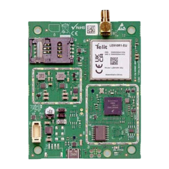
Montage-Anschluss-Anleitung Übersicht Platinenübersicht LTE-Modul Antennenanschluss SIM-Kartenhalter Schraubverbindungen zur mechanischen Befestigung Versorgungs- und Controllschnittstelle zur MB-Secure PRO USB-C Buchse, Verbindung zur MB-Secure PRO Einsetzen der SIM-Karte Es wird empfohlen vor der Montage des LTE-Moduls in das Zentralengehäuse die GSM-SIM Karte in den SIM Halter einzusetzen. Für den Betrieb wird eine Mini- SIM Karte verwendet. - Seite 11 Montage-Anschluss-Anleitung Öffnen SIM Halter in Pfeilrichtung (OPEN) schieben. SIM Karte einsetzen Oberteil ca. 90° aufklappen, SIM Karte in die Führungen des Halters einsetzen. Seitenrichtige Position der SIM Karte beachten. Schliessen SIM Halter in Pfeilrichtung bis zum Einrasten leicht in Pfeilrichtung (LOCK) schieben.
-
Seite 12: Montageübersicht Lte-Modul Im Zentralengehäuse
Montage-Anschluss-Anleitung Montageübersicht LTE-Modul im Zentralengehäuse Die Montage des MB-Secure PRO LTE-Moduls erfolgt im entsprechenden Zentralengehäuse an der Gehäuse-Innenseite jeweils im oberen Bereich. 4 Schraubbolzen sind für die richtige Montageposition vorhanden. Die Montage erfolgt in der Weise, dass die Schraubverbindung für den Antennenanschluss des Modems jeweils in Richtung der Antenne zeigen. -
Seite 13: Antennenmontage
Montage-Anschluss-Anleitung Antennenmontage Dem LTE-Modul liegt eine GSM/LTE-Antenne mit Kabel und Schraubstecker bei. Die Antenne wird an den Antennenansschluss des LTE-Moduls angeschlossen. Kabellänge der beiliegenden Antenne 25 cm. Vor der Antennenmontage: Entfernen Sie die Schutzfolie des Antennenklebestrei- fens! Vorbereiten des Gehäuses Befestigungsdurchführung für die Antenne her- stellen. -
Seite 14: Einsetzen Der Antenne
Montage-Anschluss-Anleitung Einsetzen der Antenne Verwenden Sie grundsätzlich nur die im Lieferumfang beige- fügte Antenne für den Betrieb mit diesen LTE Modul. Falls bei schlechter Empfangs- lage der Einsatz einer abge- setzten Antenne erforderlich wird, kann die GSM Außenan- tenne (Art.-Nr. 057591.20) ver- wendet werden. -
Seite 15: Verwendung Von Abgesetzten Antennen
Montage-Anschluss-Anleitung Verwendung von abgesetzten Antennen Es besteht die Möglichkeit, bei schlechter Empfangslage des LTE-Moduls eine Verlagerung des Antennenstandorts in Betracht zu ziehen. Jedoch sollte hierbei vor einem Umbau, die Signalstärke mit einem Mobiltelefon kontrolliert werden. Bitte beachte Sie, dass es durch Witterungseinflüsse zu Schwankun- gen der Signalqualität kommen kann und auch hier ein entspre- chender Probebetrieb angebracht ist. -
Seite 16: Montage Kabeladapter Für Externe Antenne
Montage-Anschluss-Anleitung Montage Kabeladapter für externe Antenne Abgesetzte Antennen dürfen nur in Verbindung mit dem Kabel- adapter für externe Antenne verbaut werden. Der Kabeladapter besitzt zwei Schraubanschlüsse (SMA) und wird auf der Schirmanschlussleiste des entsprechenden ZG- Gehäuses mittels Schaube und Zahnscheibe fixiert. An einen der beiden Schraubanschlüsse (SMA) wird das 60 cm lange Antennenverbindungskabel zum LTE-Modem angeschlossen, an den anderen Schraubanschluss erfolgt der Anschluss des... -
Seite 17: Inbetriebnahme
Montage-Anschluss-Anleitung Inbetriebnahme WARNUNG Das LTE-Modul niemals ohne angeschlossene Antenne betreiben! Es besteht Zer- störungsgefahr der Sendeendstufe! Vor dem Einsetzen oder Entfernen der GSM-SIM Karte ist das LTE-Modul stromlos zu schalten! Kurzschlussgefahr! Hinweise zur Programmierung und LED-Anzeigen Für den Einsatz und Betrieb des LTE-Moduls sind neben der sorgfältig ausgeführten Installation, noch folgende wichtigen Punkte zu berücksichtigen Alle erforderlichen Leitungsverbindungen welche für die Spannungsversorgung der Kompo- nenten erforderlich sind, gemäß... -
Seite 18: 7.2.1 Led 1 Und Led 2 - Anzeige Bei Normalbetrieb
Montage-Anschluss-Anleitung 7.2.1 LED 1 und LED 2 - Anzeige bei Normalbetrieb Status: Modul Software Normalbetrieb LED (1) keine Betriebsspannung Blinkmode 1 pro Sekunde 100ms grün aufblitzen ► Startup (max. 20 Sek) Blinkmode 2 LED blinkt 1/2 Sek. grün, 1/2 Sek. aus ►... -
Seite 19: 7.2.2 Led 3 - Anzeige Gsm Status
Montage-Anschluss-Anleitung 7.2.1.1 LED 1 und LED 2 - Anzeige bei Firmware Update Status: Boot Mode bei Telit Firmware Update LED (1) keine Betriebsspannung Blinkmode 1 pro Sekunde 100ms grün aufblitzen ► Startup (max. 20 Sek). Blinkmode 2 pro Sekunde 100ms rot aufblitzen ►... -
Seite 20: Technische Daten Lte-Modul
Montage-Anschluss-Anleitung Technische Daten LTE-Modul Betriebsspannung von Einbruchmelderzentrale über Controllerschnittstelle bereitgestellt. Stromaufnahme in Ruhe 40 mA Stromaufnahme aktiver Sende- betrieb 2G bei 12V DC 280 mA Stromaufnahme aktiver Sende- betrieb 4G bei 12V DC 130 mA Frequenzbänder GSM/GPRS/EDGE: Dual band 900/1800 MHz LTE: Penta band 700 (Bd28) / 800 (Bd20) / 900 (Bd8) / 1800 (Bd3) / 2100 MHz (Bd1) / 2600 (Bd7) Ausgangsleistungen abhängig... - Seite 21 Secure PRO (Art.-Nr. MB-PRO4000BASE) mit der Option LTE-Modul Art.-Nr. MB- CM001, der Richtlinie 2014/53/EU entspricht. Der vollständige Text der EU-Konformitätserklärung steht auf unserer Homepage https:// www.se- curity.honeywell.de/ im Service/Downloadbereich zum Download bereit. Anerkennungen VdS-Anerkennung G123802 als Option Art.-Nr. MB-CM001 für die Einbruchmel- dezentrale MB Secure MB-PRO4000BASE mit integrierter Alarmüberübertragung.
- Seite 22 LTE-Modem for MB-Secure PRO Contents General Information....................Application....................Supported devices.................. Requirements for transmission paths............. Transmission system and transmission paths........Possible applications................... GSM-GPRS-LTE transmission............... Redundant transmission path..............Transmission path without redundancy..........Notes on GSM and SIM card contract..............Notes on installation, commissioning and safety........Notes about mobile network card contract..........
-
Seite 23: Safety Instructions
LTE-Modem for MB-Secure PRO Safety instructions All of the instructions should be carefully read before you install and commission the device. You will find important information on assembly, programming and operation. This device has been manufactured as per state-of-the-art technology. Use this device only: –... -
Seite 24: General Information
LTE-Modem for MB-Secure PRO General Information Application The LTE module with item no. MB-CM001 is used to add a transmission path to the integrated transmission device of an MB-Secure PRO panel. Up to two LTE module can be connected to an MB-Secure PRO panel. -
Seite 25: Transmission System And Transmission Paths
MB-Secure PRO panel. The scope of delivery includes one GSM antenna, which is suitable for universal installation on the Honeywell ZG panel housing types. The LTE module enables the digital transmission of technical fault messages, hazard alarms and emergency calls via GSM networks to a centre providing assistance (security company). -
Seite 26: Possible Applications
LTE-Modem for MB-Secure PRO Possible applications GSM-GPRS-LTE transmission The LTE module (Item no. MB-CM001) and the MB-Secure PRO alarm control panel can be used to establish connections to IP data networks via the Internet. This is done using the GSM service GPRS (General Packet Radio Service) and LTE (Long Term Evolution). -
Seite 27: Notes On Gsm And Sim Card Contract
LTE-Modem for MB-Secure PRO Notes on GSM and SIM card contract Notes on installation, commissioning and safety For proper operation of the LTE module, the following instructions must be observed!. During the project planning phase, first establish which GSM network is available in the building under surveillance. -
Seite 28: Notes About Mobile Network Card Contract
LTE-Modem for MB-Secure PRO Information for permanently mounted wireless terminal devices Information for permanently mounted wireless terminal devices - the following additional noti- fications apply for wireless devices in a fixed location with their own power connection. Since the measurement methods for the SAR value can only be applied for use close to the head or body, safety is ensured for permanently mounted mobile radio devices by specifying a dis- tance. -
Seite 29: Overview
LTE-Modem for MB-Secure PRO Overview Overview LTE module Antenna connection SIM card holder Screw connections for mechanical fixing Supply and control interface to MB-Secure PRO panel USB socket (type USB-C), Connection to MB-Secure PRO panel Inserting the SIM card We recommend inserting the GSM SIM card into the SIM holder before installing the LTE module in the centre housing. - Seite 30 LTE-Modem for MB-Secure PRO Open Slide the SIM holder in the direction of the arrow (OPEN). Insert SIM card Open the upper part by approx. 90° and insert the SIM card into the guides of the holder. Ensure that the SIM card is positioned correctly.
-
Seite 31: Installation Overview Lte Module In The Control Panel Housing
LTE-Modem for MB-Secure PRO Installation overview LTE module in the control panel housing The MB-Secure PRO LTE module is mounted in the corresponding centre housing on the inside of the housing in the upper housing position. There are 4 screw bolts for the correct mounting position. -
Seite 32: Antenna Installation
LTE-Modem for MB-Secure PRO Antenna installation The LTE module comes with a GSM/LTE antenna with cable and screw plug connector. The antenna is connected to the antenna connection of the LTE-module. Cable length of the enclosed antenna 25 cm. Before mounting the antenna: Remove the protective film from the antenna adhe- sive strip! Preparing the housing Make a mounting feed-through opening for the... -
Seite 33: Detailed View Of Antenna Connection
LTE-Modem for MB-Secure PRO Attach the antenna to the housing feed-through. Insert the antenna into the housing feed- through and secure it using the washer and fastening screw. Only tighten the antenna so that it cannot be rotated. Connect the antenna cable to the LTE module using the SMA connector. -
Seite 34: Use Of Remote Antennas
LTE-Modem for MB-Secure PRO Use of remote antennas Is possible to consider relocating the antenna site if the recep- tion of the LTE-module is poor. However even in the event of relocation, the signal strength should be checked with a mobile phone. -
Seite 35: Mounting The Cable Adapter
LTE-Modem for MB-Secure PRO Mounting the cable adapter Remote antennas may only be installed with the cable adapter PCB for external antennas. The cable adapter has two screw connectors (SMA) and is mounted to the shield terminal block of the corresponding ZG housing using a screw and toothed washer. -
Seite 36: Commissioning
LTE-Modem for MB-Secure PRO Commissioning WARNING Never operate the LTE module without a connected antenna! Danger of destroying the transmitter output stage! Before inserting or removing the GSM SIM card, the LTE module must be discon- nected from the power supply! Risk of short circuits! Notes on programming and LED displays In addition to careful installation, the following important points must be taken into account when using and operating the LTE module... -
Seite 37: 7.2.1 Led 1 And Led 2 - Display During Normal Operation
LTE-Modem for MB-Secure PRO 7.2.1 LED 1 and LED 2 - Display during normal operation State: Module Software normal operation LED (1) No operating voltage Flashing pattern 1 flash green 100 ms per second ► Startup (max. 20 seconds) Flashing pattern 2 LED flashes green 1/2 second, 1/2 second off ►... -
Seite 38: 7.2.2 Led 3 - Display Of Cellular Network Status
LTE-Modem for MB-Secure PRO 7.2.1.1 LED 1 and LED 2 - Display during firmware update State: Boot mode for Telit firmware update LED (1) No operating voltage Flashing pattern 1 Flash green 100 ms per second ► Startup (max. 20 seconds). Flashing pattern 2 Flash red 100 ms per second ►... -
Seite 39: Technical Data Lte Module
LTE-Modem for MB-Secure PRO Technical data LTE module Operating voltage provided by the alarm control panel via the controller inter- face. Current consumption idle state 40 mA Current consumption active transmission mode 2G at 12V DC 280 mA Current consumption active transmission mode 4G bei 12V 130 mA Frequency bands... - Seite 40 MB-PRO4000BASE) with the option LTE module item no. MB-CM001, com- plies with Directive 2014/53/EU. The complete text of the EU Declaration of Conformity is available for download on our homepage https:// www.security.honeywell.de/ in the Service/Download area. Approvals SAFETY INSTRUCTIONS VdS approval G123802 as option item no.
- Seite 41 LTE-Modem for MB-Secure PRO...
- Seite 42 LTE-Modem for MB-Secure PRO...
- Seite 43 LTE-Modem for MB-Secure PRO...
- Seite 44 Honeywell | Commercial Security Novar GmbH Berliner Strasse 111 D-40880 Ratingen Postanschrift Johannes-Mauthe-Straße 14 P_MB-CM001_10_02_B D-72458 Albstadt 2025-07-14 www.security.honeywell.de © 2025 Novar GmbH...