Lenze EPM-H310 Betriebsanleitung
Vorschau ausblenden
Andere Handbücher für EPM-H310:
- Betriebsanleitung (104 Seiten) ,
- Betriebsanleitung (22 Seiten)

Verwandte Anleitungen für Lenze EPM-H310


Inhaltszusammenfassung für Lenze EPM-H310
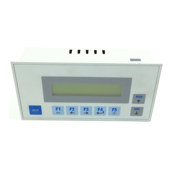
- Seite 1 Show/Hide Bookmarks EDBEPM-H310 !Ju6 Betriebsanleitung Operating Instructions Instructions de mise en service Help Info shift Global Drive EPM-H310...
- Seite 2 Show/Hide Bookmarks...
-
Seite 3: Über Diese Anleitung
Komplette Überarbeitung zur Serie ã 2001 Lenze GmbH & Co KG Ohne besondere schriftliche Genehmigung von Lenze GmbH & Co KG darf kein Teil dieser Dokumentation vervielfältigt oder Dritten zugänglich gemacht werden. Wir haben alle Angaben in dieser Dokumentation mit größter Sorgfalt zusammengestellt und auf Übereinstimmung mit der beschriebenen Hard- und Software geprüft. -
Seite 4: Inhaltsverzeichnis
Show/Hide Bookmarks Inhaltsverzeichnis 1 Vorwort und Allgemeines ........Über diese Betriebsanleitung . -
Seite 5: Vorwort Und Allgemeines
Die vorliegende Betriebsanleitung dient dem sicheren und fehlerfreien Arbeiten an und mit der Bedieneinheit EPM-H310. • Alle Personen, die an und mit der Bedieneinheit EPM-H310 arbeiten, müssen bei ihren Arbeiten die Betriebsanleitung verfügbar haben und die für sie relevanten Angaben und Hinweise beachten. -
Seite 6: Piktogramme In Dieser Betriebsanleitung
Wenn Sie ihn befolgen, erleichtern Sie sich die Handha- bung der Bedieneinheit. Lieferumfang Lieferumfang Wichtig • 1 Bedieneinheit EPM-H310 Überprüfen Sie nach Erhalt der Lieferung sofort, ob der • Lieferumfang mit den Warenbegleitpapieren überein- 1 Betriebsanleitung stimmt. Für nachträglich reklamierte Mängel über- •... -
Seite 7: Technische Daten
Show/Hide Bookmarks Technische Daten Technische Daten Allgemeine Daten und Einsatzbedingungen Bereich Werte Isolationsspannung zur Bezugserde/PE: 50 V AC Isolationsfestigkeit IP65 (Front) Schutzart im Betrieb: 0 ... +50 °C Zulässige Temperaturbereiche Transport: -20 ... +60 °C Lagerung: -20 ... +60 °C <85 %, keine Betauung Feuchtebeanspruchung Gewicht... -
Seite 8: Elektrische Daten
Show/Hide Bookmarks Technische Daten Elektrische Daten Bereich Werte Display Display Darstellungsformat Text Sichtbare Größe 73.5 × 11.5 mm Zeilen × Zeichen 2 × 20 Zeichengröße 3.2 × 5.5 mm Zeichengröße im Textmodus 5 × 7 Pixel Fonts ASCII, Katakana Kontrasteinstellung Trimmpotentiometer Hintergrundbeleuchtung Elektrischer An-... -
Seite 9: Schnittstellenbeschreibung
Show/Hide Bookmarks Technische Daten 2.2.2 Schnittstellenbeschreibung ASP8 Minidin 8pol. Buchse Signal Rx RS232 IN Tx RS232 OUT N.C. RTS RS232 OUT CTS RS232 IN N.C. H310_010 H310_010 H310_010 H310_010 H310_010 H310_010 H310_010 H310_010 Signal GND +5 VCC (reserved) N.C. Nicht angeschlossen Abmessungen Help Info... -
Seite 10: Einbauausschnitt
Show/Hide Bookmarks Technische Daten Einbauausschnitt H310_002 a [mm] b [mm] 157.0 77.0 EDBEPM-H310 DE/EN/FR 2.0... -
Seite 11: Installation
Show/Hide Bookmarks Installation Installation Mechanische Installation Die Maße für den Einbauausschnitt entnehmen Sie den technischen Daten. ( ^ 10) 1. Bedieneinheit mit Dichtung in den Einbauausschnitt schieben. H310_006 2. Befestigungsschellen in die Öffnungs- schlitze der Bedieneinheit schieben. U T : I N P N . -
Seite 12: Elektrische Installation
Show/Hide Bookmarks Installation Elektrische Installation 3.2.1 Belegung der Anschlußklemmen Stop! Um eine Beschädigung der Bedieneinheit und eines angeschlossenen PC zu vermeiden, müssen Sie • die Bedieneinheit immer im spannungslosen Zustand verdrahten, • den PE-Leiter 0 ausschließlich so verbinden, wie es in der Abbildung dargestellt ist. –... -
Seite 13: Verdrahtung Des Systembus (Can)
Show/Hide Bookmarks Installation 3.2.2 Verdrahtung des Systembus (CAN) Prinzipieller Aufbau (H310) CAN- Shield CAN+ N.C. CG LO HI CG LO HI CG LO HI CG LO H310_004 Busteilnehmer 1 Busteilnehmer 2 Busteilnehmer n • Verbinden Sie nur Klemmen gleichen Signaltyps miteinander. •... -
Seite 14: Inbetriebnahme
Show/Hide Bookmarks Inbetriebnahme Inbetriebnahme Erstes Einschalten Für die Inbetriebnahme ist eine vollständige Verdrahtung des Systembus notwendig. Stop! Überprüfen Sie vor dem Einschalten der Versorgungsspannung • die gesamte Verdrahtung auf Vollständigkeit und Kurzschluß, • ob das Bussystem beim physikalisch ersten und letzten Busteilnehmer abgeschlossen ist. EDBEPM-H310 DE/EN/FR 2.0... -
Seite 15: Projekt In Die Bedieneinheit Übertragen
Show/Hide Bookmarks Inbetriebnahme Projekt in die Bedieneinheit übertragen 4.2.1 Bedieneinheit und PC verbinden Stop! Die Verbindung zwischen PC und Bedieneinheit nur bei ausgeschalteten Geräten herstellen! LCD ADJ INPUT: 18 - 32 V 5W FUSE 315 mA +24 VDC 0 VDC N.C. -
Seite 16: Projekt Downloaden
Show/Hide Bookmarks Inbetriebnahme 4.2.2 Projekt downloaden Im HMI Designer können Sie auswählen, ob mit dem Laden des Projekts gleichzeitig die Firmware ak- tualisiert werden soll. • Aktualisieren Sie die Firmware immer: – Beim ersten Download eines Projekts in die Bedieneinheit. –... -
Seite 17: Verbindung Zum Pc Entfernen
Die zuletzt aufgetretene Störung (Error) Sie möchten ... Drücken Sie die Tasten ... Beispiel den Status der Bedieneinheit abfragen shift Driver: Driver: Can Lenze M Can Lenze M Ver. : Ver. : 1.05 1.05 die nächste Statusseite anwählen. Info Help oder Addr. -
Seite 18: Bedienung
Show/Hide Bookmarks Bedienung Bedienung Tastenfunktionen <F1> Funktion von F1 ausführen (Taste programmierbar) shift <Esc> Parametereingabe zurücksetzen; Hilfe- bzw. Info-Seite verlassen <F2> Funktion von F2 ausführen (Taste programmierbar) shift ß Menü-Ebene: Cursor in die vorherige Zeile stellen <Pfeil links> ß Parameter-Ebene: Cursor auf die vorherige Ziffer stellen <F3>... -
Seite 19: Daten Eingeben
Show/Hide Bookmarks Bedienung Daten eingeben Das Eingeben oder Ändern von Daten ist Schritt für Schritt dargestellt und wird an einem Beispiel erläu- tert. Sie möchten ... Drücken Sie die Tasten ... Beispiel ein Menü auswählen. shift eine Seite anwählen. Info Help oder â... -
Seite 20: Informationsmeldung Aufrufen
Show/Hide Bookmarks Bedienung Sie möchten ... Drücken Sie die Tasten ... Beispiel ein dynamisches Textfeld ändern. 1. Wählen Sie den Text aus. Info Help oder Feld 1 Feld 1 á â Feld 2 Feld 2 -9876 -9876 2. Bestätigen Sie die Eingabe. –... -
Seite 21: Hilfe Aufrufen
Show/Hide Bookmarks Bedienung Hilfe aufrufen • Hilfemeldungen – können Seiten oder Informationsmeldungen zugeordnet sein. – enthalten nützliche Hinweise, die die Bedienung erleichtern. – müssen im Projektierungstool “HMI Designer” programmiert worden sein. • Die Bedieneinheit signalisiert nicht, ob zu einer Seite oder einer Informationsmeldung eine Hilfemeldung vorhanden ist. -
Seite 22: Fehlersuche Und Störungsbeseitigung
Show/Hide Bookmarks Fehlersuche und Störungsbeseitigung Fehlersuche und Störungsbeseitigung Störungsmeldungen Rufen Sie die Statusmeldungen der Bedieneinheit auf, um die zuletzt aufgetretene Störungsmeldung anzuzeigen. ( ^ 17) Display ( ERROR ) Störung Ursache Abhilfe Keine Störung NO ERROR • Fehlerhafter Verbindung zwischen Bedien- Anschlüsse auf festen Sitz prüfen PR ERROR Datenaus-... -
Seite 23: Wartung
– Wenn Sie ein anderes Reinigungsmittel verwenden müssen, um Verunreinigungen zu beseitigen, beachten Sie die Angaben in der Tabelle im Kap. 8.1. ( ^ 24) Serviceadressen Die Adressen Ihrer Lenze-Ansprechpartner in aller Welt finden Sie auf der hinteren Umschlagseite jeder Lenze-Druckschrift. EDBEPM-H310 DE/EN/FR 2.0... -
Seite 24: Anhang
Die folgende Tabelle zeigt die Beständigkeit der Bedien-Oberfläche (Tastatur, Display, Touch Screen) gegen die genannten Chemikalien. Stop! Die Bedien-Oberfläche ist wenig beständig gegen saure Nahrungsmittel (z. B. Tomatensaft, Zitronensaft). Verschmutzungen deshalb gleich entfernen, sonst kann die Oberfläche beschädigt werden. Bedieneinheit EPM-H310 EPM-H410 EPM-H510 Substanz EPM-H315 EPM-H520 Aceton —... -
Seite 25: Stichwortverzeichnis
Show/Hide Bookmarks Anhang Stichwortverzeichnis Daten, eingeben, 19 Abmessungen DC-Spannungsversorgung, 8 Bedieneinheit, 9 Einbauausschnitt, 10 Display, 8 Kontrast einstellen, 17 Anschluß, elektrischer, 8 Anschlußklemmen, Belegung, 12 Antriebsregler, 5 Eigenschaften, 8 Einsatzbedingungen, 7 Feuchtebeanspruchung, 7 Isolationsfestigkeit, 7 Baudrate, Systembus (CAN), 8 Schutzart, 7 zulässige Temperaturbereiche, 7 Bedieneinheit Einsatzbereich, 5... - Seite 26 Show/Hide Bookmarks Anhang Schutzart, 7 Informationsmeldung, 20 Serviceadressen, 23 Installation, 11 Sicherheitshinweise, Gestaltung Anschlußklemmen, Belegung, 12 Sonstige Hinweise, 6 elektrische, 12 Warnung vor Sachschäden, 6 mechanische, 11 Speicher, 8 Systembus (CAN), 13 Statusmeldungen, 17 Isolationsfestigkeit, 7 Störungsmeldungen, 22 Systembus (CAN) Baudrate, 8 Kommunikationsmedium, 8 Kontrast, einstellen, 17...
- Seite 27 Show/Hide Bookmarks About these Instructions This documentation only applies to the keypad EPM-H310 as of version: EPM-H310 Type Hardware version Software version Version Id-No. Changes – 03/2000 TD23 00414158 First edition for field test 08/2001 TD02 00418421 Complete revision for series production ã...
- Seite 28 Show/Hide Bookmarks Contents 1 Preface and general information ........About these Operating Instructions .
-
Seite 29: Preface And General Information
Preface and general information Preface and general information The EPM-H310 keypad can be used to access codes of Lenze controllers, 9300 Servo PLC and Drive PLC and to facilitate the use of these devices. The HMI Designer is the powerful development environment for creating projects containing the configuration of the keypad. -
Seite 30: Pictograms Used In These Operating Instructions
• 1 EPM-H310 keypad After receipt of the delivery, check immediately whether • the items delivered match the accompanying papers. 1 Operating Instructions Lenze does not accept any liability for deficiencies • 2 Mounting clamps claimed subsequently. • 2 Screws Report •... -
Seite 31: Technical Data
Show/Hide Bookmarks Technical data Technical data General data and application conditions Field Values Insulation resistance to PE: 50 V AC Insulation resistance IP65 (front) Type of protection during operation: 0 ... +50 °C Permissible temperature range during transport: -20 ... +60 °C during storage -20 ... -
Seite 32: Electrical Data
Show/Hide Bookmarks Technical data Electrical data Field Values Display Display Type Display format Text Visible size 73.5 x 11.5 mm Lines x characters 2 x 20 Character size 3.2 x 5.5 mm Character size in text mode 5 x 7 pixels Fonts ASCII, Katakana Contrast setting... -
Seite 33: Interface Description
Show/Hide Bookmarks Technical data 2.2.2 Interface description ASP8 Minidin 8 pole female plug Signal Rx RS232 IN Tx RS232 OUT N.C. RTS RS232 OUT CTS RS232 IN N.C. H310_010 H310_010 H310_010 H310_010 H310_010 H310_010 H310_010 H310_010 Signal GND +5 VCC (reserved) N.C. -
Seite 34: Mounting Cut-Out
Show/Hide Bookmarks Technical data Mounting cut-out H310_002 a [mm] b [mm] 157.0 77.0 EDBEPM-H310 DE/EN/FR 2.0... -
Seite 35: Installation
Show/Hide Bookmarks Installation Installation Mechanical installation The dimensions for mounting cut-out can be found in the Technical Data ( ^ 34) 1. Insert the keypad and the into the cut-out. H310_006 2. Insert the fixing clamps into the slots on the keypad. U T : I N P N . -
Seite 36: Electrical Installation
Show/Hide Bookmarks Installation Electrical installation 3.2.1 Assignment of the connection terminals Stop! Damage to the keypad and the connected PC can be avoided by • wiring the keypad only when the voltage has been disconnected, • connecting the PE conductor 0 as shown in the diagram. –... -
Seite 37: System Bus Wiring (Can)
Show/Hide Bookmarks Installation 3.2.2 System bus wiring (CAN) Schematic diagram (H310) CAN- Shield CAN+ N.C. CG LO HI CG LO HI CG LO HI CG LO H310_004 Bus device 1 Bus device 2 Bus device n • Only connect terminals of the same signal type. •... -
Seite 38: Commissioning
Show/Hide Bookmarks Commissioning Commissioning First switch on For commissioning, the system bus must be completely wired. Stop! Before switching on the supply voltage: • Check the wiring for completeness and short circuits, • Check whether the bus system is terminated physically at the first and last device. EDBEPM-H310 DE/EN/FR 2.0... -
Seite 39: Transferring The Project To The Keypad
Show/Hide Bookmarks Commissioning Transferring the project to the keypad 4.2.1 Connection of keypad and PC Stop! Only connect PC and keypad when the units are switched off! LCD ADJ INPUT: 18 - 32 V 5W FUSE 315 mA +24 VDC 0 VDC N.C. -
Seite 40: Project Download
Show/Hide Bookmarks Commissioning 4.2.2 Project download The HMI designer can be used to load the project and update the firmware at the same time. • Always update the firmware: – When downloading a project into the keypad for the first time. –... -
Seite 41: Disconnection From The Pc
If you want to ... Press keys ... Example query the status of the keypad shift Driver: Driver: Can Lenze M Can Lenze M Ver. : Ver. : 1.05 1.05 select the next status page Info Help Addr. -
Seite 42: Operation
Show/Hide Bookmarks Operation Operation Key functions <F1> Execute function of F1 (programmable key) shift <Esc> Reset parameter input; quit help or info page <F2> Execute function of F2 (programmable key) shift ß Menu level: Place cursor in previous line <Left arrow> ß... -
Seite 43: Data Input
Show/Hide Bookmarks Operation Data input Data input and modification are described step-by-step using examples. If you want to ... Press keys ... Example select a menu. shift go to a page. Info Help â á set the cursor to the previous or next field. Field 1 Field 1 ß... -
Seite 44: Calling Up Information Messages
Show/Hide Bookmarks Operation If you want to ... Press keys ... Example change a dynamic text field. 1. Select the text. Info Help Field 1 Field 1 á â Field 2 Field 2 -9876 -9876 2. Confirm the input. – The cursor changes to the menu level. Calling up information messages •... -
Seite 45: Calling Up Help
Show/Hide Bookmarks Operation Calling up help • Help messages – can be assigned to pages or information messages. – contain useful notes to make handling easier. – must have been programmed in the planning tool “HMI Designer”. • The keypad does not indicate whether a help message is available for a page or an information message. -
Seite 46: Troubleshooting And Fault Elimination
Show/Hide Bookmarks Troubleshooting and fault elimination Troubleshooting Error messages Call up the keypad status messages to see the last error message. ( ^ 41) Display ( ERROR ) Error Cause Remedy No error NO ERROR • Faulty data Connection between keypad Check connection PR ERROR •... -
Seite 47: Maintenance
– If you use any other cleaning agents, please see the table in chapter 8.1. ( ^ 48) Service addresses The addresses of all Lenze representatives world-wide are listed on the last page of every Lenze document. EDBEPM-H310 DE/EN/FR 2.0... -
Seite 48: Appendix
The following table showns the resistance of the surfaces (keypad, display, touch screen) to the listed chemicals. Stop! The surfaces do not resist acidic food (e.g. tomato juice, lemon juice) very well. We therefore recommend to clean off these marks immediately, otherwise the surface can be damaged. Keypad EPM-H310 EPM-H410 EPM-H510 Substance EPM-H315 EPM-H520 Acetone —... -
Seite 49: Table Of Keywords
Show/Hide Bookmarks Appendix Table of keywords First switch on, 38 Application conditions, 31 Humidity, 31 Insulation resistance, 31 Permissible temperature range, 31 Help, 45 Type of protection, 31 Human Machine Interface, 29 Humidity, 31 Baud rate, System bus (CAN), 32 Information message, 44 Installation, 35 Connection terminals, Assignment, 36... - Seite 50 Show/Hide Bookmarks Appendix Safety Instructions, Layout Other notes, 30 Output, 41 Warning of damage to materal, 30 Scope of supply, 30 Service addresses, 47 Switch on, first, 38 System bus (CAN) Parameters, 32 Baud rate, 32 Communication medium, 32 Wiring, 37 Connection with the keypad, 39 Diconnection from the keypad, 41 Technical data...
-
Seite 51: Information Générale
Show/Hide Bookmarks Information générale Le présent document s’applique à l’unité de commande EPM-H310 à partir de la version : EPM-H310 Type Version du matériel Version du logiciel Edition N° d’ident. Modifications – 03/2000 TD23 00414158 Première édition pour essais sur le terrain... - Seite 52 Show/Hide Bookmarks Table des matières 1 Avant-propos et généralités ........Comment utiliser ces instructions de mise en service .
-
Seite 53: Avant-Propos Et Généralités
Avant-propos Avant-propos et généralités L’unité de commande EPM-H310 permet d’accéder aux codes des variateurs de vitesse Lenze, du Servo PLC 9300 et du Drive PLC et de commander ces appareils de façon conviviale. L’outil de conception performant HMI Designer vous permet d’établir des projets comprenant la configuration de l’unité... -
Seite 54: Pictogrammes Utilisés Dans Le Présent Fascicule
Equipement livré Equipement livré IMPORTANT • 1 unité de commande EPM-H310 Vérifier à réception que l’équipement livré est • conforme au bon de livraison. Aucune réclamation ne 1 documentation ”Instructions de mise en service”... -
Seite 55: Spécifications Techniques
Show/Hide Bookmarks Spécifications techniques Spécifications techniques Caractéristiques générales et conditions ambiantes Domaine Données Tension d’isolement bus - point de terre/PE : 50 V CA Résistance à l’isolement IP65 (face avant) Protection Fonctionnement 0 ... +50 °C Plages de température admissibles Transport -20 ... -
Seite 56: Caractéristiques Électriques
Show/Hide Bookmarks Spécifications techniques Caractéristiques électriques Domaine Données Affichage Affichage Type Format de présentation Texte Taille d’affichage 73,5 x 11,5 mm Lignes x caractères 2 x 20 Taille de caractères 3,2 x 5,5 mm Taille caractère en mode texte 5 x 7 pixel Fontes ASCII, Katakana Réglage des contrastes... -
Seite 57: Affectation De La Prise
Show/Hide Bookmarks Spécifications techniques 2.2.2 Affectation de la prise ASP8 Prise Minidin 8 broches Broche Signal Rx RS232 IN Tx RS232 OUT N.C. RTS RS232 OUT CTS RS232 IN N.C. H310_010 H310_010 H310_010 H310_010 H310_010 H310_010 H310_010 H310_010 Signal GND +5 VCC (réservé) N.C. -
Seite 58: Encoche De Montage
Show/Hide Bookmarks Spécifications techniques Encoche de montage H310_002 a [mm] b [mm] 157,0 77,0 EDBEPM-H310 DE/EN/FR 2.0... -
Seite 59: Installation
Show/Hide Bookmarks Installation Installation Installation mécanique Pour les cotes de l’encoche de montage, se reporter au chapitre Spécifications techniques. ( ^ 58) 1. Glisser l’unité de commande et le joint dans l’encoche de montage. H310_006 2. Placer les colliers de fixation dans les ouvertures prévues à... -
Seite 60: Installation Électrique
Show/Hide Bookmarks Installation Installation électrique 3.2.1 Affectation des bornes Stop ! Afin d’éviter tout endommagement de l’unité de commande et du PC connecté, • ne raccorder l’unité de commande qu’en absence de tension, • ne raccorder le câble de mise à la terre PE 0 uniquement comme indiqué sur l’illustration. –... -
Seite 61: Câblage Du Bus Système (Can)
Show/Hide Bookmarks Installation 3.2.2 Câblage du bus système (CAN) Principe de câblage (H310) CAN- Shield CAN+ N.C. CG LO HI CG LO HI CG LO HI CG LO H310_004 Abonné au bus 1 Abonné au bus 2 Abonné au bus n •... -
Seite 62: Mise En Service
Show/Hide Bookmarks Mise en service Mise en service Première mise en service Pour la mise en service, il est impératif que le bus système soit correctement raccordé. Stop ! Avant la mise sous tension, vérifier • le câblage dans son intégralité pour éviter un court-circuit, •... -
Seite 63: Transférer Le Projet Dans L'unité De Commande
Show/Hide Bookmarks Mise en service Transférer le projet dans l’unité de commande 4.2.1 Relier l’unité de commande et le PC Stop ! Ne relier le PC et l’unité de commande qu’en absence de tension ! LCD ADJ INPUT: 18 - 32 V 5W FUSE 315 mA +24 VDC... -
Seite 64: Télécharger Un Projet
Show/Hide Bookmarks Mise en service 4.2.2 Télécharger un projet L’outil de conception HMI Designer vous permet de déterminer si, simultanément au chargement du projet, le micrologiciel doit être actualisé. • Il faut toujours procéder à l’actualisation du logiciel – lors du premier téléchargement d’un projet dans l’unité de commande, et –... -
Seite 65: Déconnexion Du Pc
Dernier défaut apparu (Error) Pour ... appuyer sur les touches : Exemple connaître l’état de l’unité de commande shift Driver: Driver: Can Lenze M Can Lenze M Ver. : Ver. : 1.05 1.05 sélectionner la page d’état suivante Info Help Addr. -
Seite 66: Commande
Show/Hide Bookmarks Commande Commande Fonction des touches <F1> Exécuter la fonction de F1 (touche programmable). shift Remettre le paramètre à la valeur initiale ; quitter la page Help <Esc> (aide) ou la page Info (information). <F2> Exécuter la fonction de F2 (touche programmable). shift ß... -
Seite 67: Entrer Des Données
Show/Hide Bookmarks Commande Entrer des données L’ordre chronologique pour l’entrée et la modification des données est décrit à l’aide d’un exemple. Pour ... appuyer sur les touches : Exemple sélectionner un menu shift sélectionner une page Info Help â á placer le curseur sur le champ suivant ou le Champ 1 Champ 1... -
Seite 68: Appeler Un Message D'information
Show/Hide Bookmarks Commande Pour ... appuyer sur les touches : Exemple modifier une zone de description dynamique 1. Sélectionner le texte. Info Help Champ 1 Champ 1 â á Champ 2 Champ 2 -9876 -9876 2. Valider. – Le curseur passe au niveau menu. Appeler un message d’information •... -
Seite 69: Appeler Un Message D'aide
Show/Hide Bookmarks Commande Appeler un message d’aide • Les messages d’aide – peuvent être affectés aux pages ou aux messages d’information ; – contiennent des conseils pratiques facilitant la commande ; – doivent avoir été programmés dans l’outil de conception ”HMI Designer”. •... -
Seite 70: Détection Et Élimination Des Défauts
Show/Hide Bookmarks Détection et élimination des défauts Détection et élimination des défauts Messages défauts Appeler les messages d’état de l’unité de commande pour afficher le dernier défaut apparu. ( ^ 65) Affichage Défaut Origine Remède ( ERROR ) Sans défaut NO ERROR •... -
Seite 71: Maintenance
8.1. ( ^ 72) Adresses S.A.V. Vous trouverez les adresses du S.A.V. ou des agences LENZE dans le monde entier sur la dernière page de la couverture de chaque documentation Lenze. EDBEPM-H310 DE/EN/FR 2.0... -
Seite 72: Annexe
L’interface opérateur est peu résistante aux produits alimentaires acides (exemples : jus de tomate, jus de citron). En cas de projection de produits acides sur l’interface opérateur, il faut la nettoyer immédiatement sous risque de l’endommager. Unité de commande EPM-H310 EPM-H410 EPM-H510 Substance... -
Seite 73: Index
Show/Hide Bookmarks Annexe Index Encombrements Adresses S.A.V., 71 Encoche de montage, 58 Affichage, 56 Unité de commande, 57 Réglage des contrastes, 65 Equipement livré, 54 Aide, 69 Alimentation CC, 56 Fonction des touches, 66 Bornes de raccordement, Affectation, 60 Bus système (CAN) Human Machine Interface Câblage, 61 (Interface homme-machine), 53... - Seite 74 Show/Hide Bookmarks Annexe Spécifications techniques Affichage, 56 Alimentation CC, 56 Bus système (CAN), 56 Déconnexion de l’unité de commande, 65 Caractéristiques générales/conditions ambiantes, 55 Relier l’unité de commande et le PC, 63 Mémoire, 56 Poids, 55 Plages de température admissibles, 55 Puissance absorbée, 56 Raccordement électrique, 56 Poids, 55...