Herunterladen Diese Seite drucken

Werbung

Verfügbare Sprachen

Verfügbare Sprachen

Softstarters Type PSE18...PSE370
User Manual short form
0
0 0 -7
1 8 -6
P S E
0
0 0 -7
1 8 -6
P S E
0
0 0 -7
1 8 -6
P S E

Werbung

Fehlerbehebung

loading

Inhaltszusammenfassung für ABB PSE142

  • Seite 1 Softstarters Type PSE18...PSE370 User Manual short form 0 0 -7 1 8 -6 P S E 0 0 -7 1 8 -6 P S E 0 0 -7 1 8 -6 P S E...
  • Seite 2 according to EN /IEC 60947-4-2 This manual belongs to: ___________________________________________________________ 2 Softstarters Type PSE18...PSE370 User Manual short form 1SFC132059M9901...
  • Seite 3 1 Read me irst Thank you for selecting this ABB PSE Softstarter. Read carefully and be sure to understand all instructions before mounting, connecting and coniguring the Softstarter. This manual is a short form manual intended for quick and easy instal- lation of the PSE Softstarter.
  • Seite 4 40 °C (104 °F) and above 1000 m (3281 ft). For more details see Softstarters Type PSE18...PSE370, Installation and Com- missioning Manual, Document ID 1SFC132057M0201 available on: http://www.abb.com/lowvoltage. Make sure that any of the recommended short circuit protections are used according to prevailing standards.
  • Seite 5 3 Mounting The PSE Softstarters exist in three different physical sizes which are designed to be mounted with M6 bolts, or bolts of equivalent dimension and strength. Identify the correct drawing with dimensions for your softstarter Verify the drilling plan. In applications where the softstarter is installed in an enclosure, make sure that the enclosure size is not smaller than the minimum recom- mended.
  • Seite 6 4 Connection This product has been carefully manufactured and tested but there is a risk that damage can occur from such as transportation and incorrect handling. Therefore, the procedure below should be followed during initial installation: Hazardous voltage. Will cause death or serious injury. Turn off and lock out all power supplying this device before starting work on this equip- ment.
  • Seite 7 Capacitors for power factor compensation are not allowed between the softstarter and the motor, since this can cause current peaks which can damage the thyristors in the softstarter. If such capacitors are to be used, they should be connected on the line side of the softstarter. Connect control supply voltage to terminals 1 and 2.
  • Seite 8 Switch ON the control supply voltage, terminals 1 and 2. Continue to conigure parameters as described in chapter 6, Settings. Switch ON the operational voltage. There is some lexibility in the connecting of your softstarter, but fol- lowing the steps above will enable operation of the PSE softstarter. An example of a complete installation can be found in the graphics section.
  • Seite 9: Basic Functions

    5 Basic functions The HMI consists of the parts indicated in igure 5.1. LED status indicators. Ready Protection Fault LCD display with backlight. Exit key for cancelling parameter edits and exiting one menu level. Select/Reset key for changing and storing parameter values, entering one menu level, and to reset tripping Exit Select...
  • Seite 10 6 Softstarter settings The PSE Softstarters can provide soft start and stop with two different basic functions. • Voltage ramp • Torque control ramp All PSE Softstarters need to be conigured to the rated current of the motor. Since the motor must be connected In Line, set the rated current to the value written on the rating plate of the motor.
  • Seite 11 Repeating this for a period of two seconds will unlock the LCD display, and allow changes to the parameter settings. Read the Softstarters Type PSE18...PSE370, Installation and Commis- sioning Manual, Document ID 1SFC132057M0201 available on: http:// www.abb.com/lowvoltage. 12 Softstarters Type PSE18...PSE370 User Manual short form 1SFC132059M9901...
  • Seite 12 Table 6.1: Parameter list Description Display Setting range Default Actual value setting Rated Current of motor Individual Individual Start Ramp time 1...30 s 10 s Stop Ramp time OFF, 1...30 s Initial/End Voltage 30...70 % 40 % Current Limit 1.5...7 x I e 7.0 x I e Torque Control during start OFF, On...
  • Seite 13 Table 6.2: Application settings Recommended basic setting Centrifugal fan 10 s 40 % 5.0 x I e Axial fan 10 s 40 % 5.0 x I e Centrifugal 10 s 10 s 40 % 5.0 x I e pump High pressure 10 s 10 s 50 %...
  • Seite 14: Troubleshooting

    7 Troubleshooting Depending on PSE Softstarter coniguration, different events may be signalled on the LCD. All event codes are found in table 7.1: Event list. Table 7.1: Event list Event Event Cause code SF20 Software fault Fault in software By-pass relay does not open or thyristor short Shunt fault SF3x circuit...
  • Seite 15 1 Bitte zuerst lesen Vielen Dank, dass Sie sich für diesen PSE-Sanftanlasser von ABB ent- schieden haben. Lesen Sie vor Montage, Anschluss und Koniguration des Softstarters alle Anweisungen genau durch. Dieses Handbuch ist eine Kurzanleitung zur schnellen und einfachen Installation des PSE-Softstarters. Ausführliche Informationen siehe „...
  • Seite 16 Lastminderung anzusetzen. Weitere Infor- mationen siehe „Sanftanlasser Type PSE18...PSE370, Handbuch für Installation und Inbetriebnahme“, Dokumenten-ID 1SFC132057M0101, abrufbar auf: http://www.abb.com/lowvoltage. Stellen Sie sicher, dass eine der empfohlenen Kurzschlusssicherungen entsprechend den lokalen Vorschriften angewendet werden. Softstarter Typ PSE18...PSE370 Kurzbetriebsanleitung 1SFC132059M9901 29...
  • Seite 17: Montage

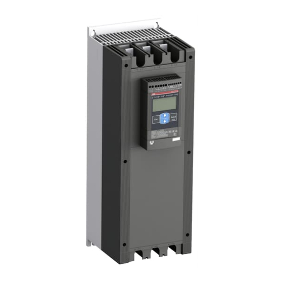
    3 Montage Die PSE-Softstarter sind in drei verschiedenen Größen erhältlich und werden mit M6-Schrauben oder Schrauben mit ähnlichen Abmessun- gen und Stärken montiert. Ermitteln Sie die richtige Zeichnung mit den Abmessungen Ihres Soft- starters. Vergleichen Sie mit der Bohrzeichnung. Wenn der Softstarter in einem Gehäuse installiert wird, stellen Sie sicher, dass das Gehäuse die empfohlenen Mindestmaße nicht unter- schreitet.
  • Seite 18 4 Anschluss Dieses Product wurde sorgfältig hergestellt und geprüft, es besteht aber die Gefahr, dass Beschädigungen durch Transport oder unsachgemäße Behandlung aufgetreten sind. Daher sollte bei der ersten Installation das Verfahren unten durchgeführt werden: Gefährliche Spannung. Führt zu schweren Verletzungen oder zum Tod. Schalten Sie vor der Arbeit an diesem Gerät dessen gesamte Energie- versorgung sicher aus.
  • Seite 19 Das Anschließen von Kondensatoren zur Kompensation des Leistungs- faktors zwischen Softstarter und Motor ist nicht erlaubt, da dies zu Stromspitzen und damit zum Durchbrennen der Thyristoren im Soft- starter führen kann. Wenn solche Kondensatoren verwendet werden, müssen Sie an der Netzseite des Softstarters angeschlossen werden. Schließen Sie die Steuerspannungsversorgung an Klemme 1 und 2 an.
  • Seite 20 Schalten Sie die Steuerspannungsversorgung (Klemme 1 und 2) an. Fahren Sie mit der Koniguration der Parameter, wie in Kapitel 6 „Ein- stellungen“ beschrieben, fort. Schalten Sie die Betriebsspannung ein. Der Anschluss des Softstarters kann zwar auch etwas abweichen, mit der Einhaltung der oben genannten Schritte ist der Betrieb des PSE-Softstarters jedoch gewährleistet.
  • Seite 21 5 Grundfunktionen Das Display besteht aus den in Abbildung 5.1 dargestellten Teilen. LED-Statusanzeigen Ready Protection Fault LCD-Anzeige mit Beleuchtung Exit-Taste zum Abbrechen von Pa- rametereingaben und zum Verlassen einer Menüebene. Select/Reset-Taste zum Ändern und Speichern von Parametern, zur Exit Select Auswahl einer Menüebene, und zum Reset Zurücksetzen von Auslöseereignissen.
  • Seite 22: Einstellungen Des Softstarters

    6 Einstellungen des Softstarters Der PSE-Softstarter kann sanfte Starts und sanfte Stopps mit zwei verschiedenen Grundfunktionen steuern. • Spannungsregelung • Drehmomentregelung Alle PSE-Softstarter müssen auf den Nennstrom des Motors eingen- stellt werden. Da der Motor in Reihe angeschlossen werden muss, setzen Sie den Nennstrom auf den auf dem Motor angegebenen Wert.
  • Seite 23 Ändern geschützt. Durch nochmaliges Gedrückthalten beider Navigationstasten für zwei Sekunden wird die LCD-Anzeige wieder entsperrt und für Parameterän- derungen freigegeben. Weitere Informationen siehe „Sanftanlasser Type PSE18...PSE370, Handbuch für Installation und Inbetriebnahme“, Dokumenten-ID 1SF- C132057M0101, abrufbar auf: http://www.abb.com/lowvoltage. 36 Softstarter Typ PSE18...PSE370 Kurzbetriebsanleitung 1SFC132059M9901...
  • Seite 24 Tabelle 6.1: Parameterliste Beschreibung Anzeige Einstellungsbereich Standard- Aktuelle wert Einstellung Nennstrom des Motors Einzeln Einzeln Startregelzeit 1...30 s 10 s Stoppregelzeit OFF (Aus), 1...30 s Anfangs-/Endspannung 30...70 % 40 % Strombegrenzung 1,5...7 x I e 7,0 x I e Drehmomentregelung bei Start OFF (Aus), On (Ein) und Stopp Drehmomentregelung bei...
  • Seite 25 Tabelle 6,2: Anwendungseinstellungen Empfohlene Grundeinstellungen Ventilator radial 10 s 40 % 5,0 x I e Ventilator axial 10 s 40 % 5,0 x I e Kreiselpumpe 10 s 10 s 40 % 5,0 x I e Hochdruckpum- 10 s 10 s 50 % 5,5 x I e Kompressor...
  • Seite 26: Fehlersuche

    7 Fehlersuche Je nach Koniguration des PSE-Softstarters können verschiedene Ereignis- se auf dem LCD signalisiert werden. Tabelle 7.1 enthält alle Ereigniscodes: Ereignisliste Tabelle 7.1: Ereignisliste Ereignis- Ereignis Grund code SF20 Softwarefehler Fehler in der Software Bypass-Relais öffnet nicht oder Thyristor kurz- Shunt-Fehler SF3x geschlossen...
  • Seite 27 18.5 PSE30 18.5 PSE37 PSE45 PSE60 18.5 PSE72 PSE85 PSE105 PSE142 PSE170 PSE210 PSE250 PSE300 PSE370 PSE18 - 600 - 70 Control supply voltage: 70 = 100 - 250 V AC Operational voltage: 600 V Current rating: 18 A Softstarter range...
  • Seite 28 170M1572 315A T2L160 MA100 T2S160 MA100 PSE85-600-70 170M3819 400A T3N250 MA160 T3S250 MA160 PSE105-600-70 T3N250 MA200 T3S250 MA200 170M5809 450A PSE142-600-70 T3N250 MA200 T3S250 MA200 170M5810 500A PSE170-600-70 T4N320 PR221-I T4S320 PR221-I 170M5812 630A In320 In320 PSE210-600-70 T5N400 PR221-I T5S400 PR221-I...
  • Seite 29 100A Ts3N150TW Ts3L150TW PSE60-600-70 125A 18kA T4N250TW T4S250TW PSE72-600-70 150A T5N300TW T5S300TW PSE85-600-70 175A T5N300TW T5S300BW PSE105-600-70 225A T5N400BW T5S400BW PSE142-600-70 300A T5N400BW T5S400BW PSE170-600-70 350A 35kA 20kA T6N600BW 50kA T6S600BW PSE210-600-70 450A T6N600BW T6S800BW PSE250-600-70 500A T6N800BW T6S800BW PSE300-600-70...
  • Seite 30 6,5 mm (0.256 in) PSE 18-600-70 13 mm (0.512 in) 30 mm (1.181 in) 80 mm (3.150 in) 90 mm (3.543 in) PSE142...PSE170 6,5 mm (0.256 in) PSE142-600-70 35 mm (1.378 in) 17,5 mm (0.689 in) 113,5 mm (4.468 in) 130 mm (5.118 in)
  • Seite 31 PSE210...PSE370 6,5 mm (0.256 in) PSE210-600-70 43,75 mm 19,6 mm (1.723 in) (0.772 in) 190 mm (7.480 in) 163,5 mm (6.437 in) Softstarters Type PSE18...PSE370 User Manual short form 1SFC132059M9901 177...
  • Seite 32 PSE18...PSE105 PSE142...PSE170 1 / 4 i n M 6 ( 1 1 3 , 5 8 i n ) ( 4 . 4 6 i n ) 0 . 9 4 5 m ( 1 2 7 8 m -7 0...
  • Seite 33 PSE210...PSE370 1 / 4 i n M 6 ( 1 6 3 , 5 7 i n ) ( 6 . 4 3 -7 0 -6 0 0 2 1 0 P S E i n ) 0 . 9 4 4 m ( 2 5 3 2 m Softstarters Type PSE18...PSE370 User Manual short form 1SFC132059M9901 179...
  • Seite 34 W (mm) H (mm) D (mm) PSE18...105 PSE142...170 1000 PSE210...370 min number W (in) H (in) D (in) of latches PSE18...105 PSE142...170 PSE210...370 180 Softstarters Type PSE18...PSE370 User Manual short form 1SFC132059M9901...
  • Seite 35 (mm) (mm) (mm) (in) (in) (in) 0.787 0.394 3.937 PSE18...105 0.787 0.394 3.937 PSE142...170 0.787 0.394 3.937 PSE210...370 PSE 18-600-70 PSE 18-600-70 Softstarters Type PSE18...PSE370 User Manual short form 1SFC132059M9901 181...
  • Seite 36 182 Softstarters Type PSE18...PSE370 User Manual short form 1SFC132059M9901...
  • Seite 37 4T2 6T3 9 Nm - 80 lb.in 8 Nm - 71 lb.in Cu 75°C only (0.197 in) 10 .. 70 mm 2x10 .. 2x70 mm PSE142...170 Using connection bars Using connection module 11/6-16 UNF-2A 22 mm (0.866 in) 24 mm ATK185: AWG4 to 300kcmil (0.945 in)
  • Seite 38 AWG 24 ... 10 4 x 0,8 mm 8 9 10 11 12 13 14 (0.157 x 0.031 in) 0,2 .. 4 mm 2x0,2 .. 1,5 mm 0,2 .. 4 mm 0,5 Nm - 4,3 lb.in 2x0,2 .. 1,5 mm 184 Softstarters Type PSE18...PSE370 User Manual short form 1SFC132059M9901...
  • Seite 39 AWG 24 ... 12 3,5 x 0,6 mm 8 9 10 11 12 13 (0.138 x 0.24 in) 0,2 .. 2,5 mm 2x0,2 .. 1,5 mm 0,2 .. 2,5 mm 0,5 Nm - 4,3 lb.in 2x0,2 .. 1,5 mm Softstarters Type PSE18...PSE370 User Manual short form 1SFC132059M9901 185...
  • Seite 40 Start Stop 9 10 11 12 13 14 PSE 18-600-70 3,5 x 0,6 mm AWG 12 ... 24 8 9 10 11 12 13 (0.138 x 0.024 in) 0,2 .. 2,5 mm 2x0,2 .. 1,5 mm 0,2 .. 2,5 mm 0,5 Nm - 4,3 lb.in 2x0,2 ..
  • Seite 41 Reset 9 10 11 12 13 14 PSE 18-600-70 3,5 x 0,6 mm AWG 24 ... 12 8 9 10 11 12 13 (0.138 x 0.024 in) 0,2 .. 2,5 mm 2x0,2 .. 1,5 mm 0,2 .. 2,5 mm 0,5 Nm - 4,3 lb.in 2x0,2 ..
  • Seite 42 9 10 11 12 13 14 PSE 18-600-70 4 x 0,8 mm AWG 10 ... 24 (0.157 x 0.031 in) 8 9 10 11 12 13 14 0,2 .. 4 mm 2x0,2 .. 1,5 mm 0,2 .. 4 mm 0,5 Nm - 4,3 lb.in 2x0,2 ..
  • Seite 43 Start Stop Start Stop 1L1 3L2 5L3 Run TOR Fault 2T1 4T2 6T3 Circuit diagram PSE18...PSE370 (Fuse and contactor version) MCCB Start Stop Start Stop 1L1 3L2 5L3 Run TOR Fault 2T1 4T2 6T3 Circuit diagram PSE18...PSE370 ( MCCB version) Softstarters Type PSE18...PSE370 User Manual short form 1SFC132059M9901 189...
  • Seite 44 5 6 7 13 14 5 6 7 13 14 5 6 7 13 14 5 6 7 13 14 13 14 13 14 13 14 190 Softstarters Type PSE18...PSE370 User Manual short form 1SFC132059M9901...
  • Seite 45 Exit Select Reset Exit Select Reset Exit Select Reset Exit Select Exit Select Reset Reset Exit Select Reset Softstarters Type PSE18...PSE370 User Manual short form 1SFC132059M9901 191...
  • Seite 46 Ready Protection Fault Exit Select Reset 192 Softstarters Type PSE18...PSE370 User Manual short form 1SFC132059M9901...
  • Seite 47 Softstarters Type PSE18...PSE370 User Manual short form 1SFC132059M9901 193...
  • Seite 48 194 Softstarters Type PSE18...PSE370 User Manual short form 1SFC132059M9901...
  • Seite 49 Softstarters Type PSE18...PSE370 User Manual short form 1SFC132059M9901 195...
  • Seite 50 Contact us: ABB AB © Copyright 2011 ABB. All rights reserved. Speciications subject to changes without Cewe-Control SE-721 61 Västerås, Sweden notice. Telephone: +46 (0) 21 32 07 00 Telefax: + 46 (0) 21 12 60 01 http://www.abb.com/lowvoltage...