Mitsubishi Electric MELSEC FX2N Serie Bedienungsanleitung
Vorschau ausblenden
Andere Handbücher für MELSEC FX2N Serie:
- Bedienungsanleitung (158 Seiten) ,
- Installationsbeschreibung (36 Seiten) ,
- Programmieranleitung (830 Seiten)
Werbung
Quicklinks
Werbung

Verwandte Anleitungen für Mitsubishi Electric MELSEC FX2N Serie


Inhaltszusammenfassung für Mitsubishi Electric MELSEC FX2N Serie
- Seite 1 HARDWARE MANUAL SERIES PROGRAMMABLE CONTROLLERS...
- Seite 2 Si lors de l’installation des incertitudes persistent, n’hésitez pas à consulter un électricien compétent, • qualifié et formé à l’utilisation des normes électriques locales et nationales. Contactez le représentant le plus proche de MITSUBISHI ELECTRIC si la manipulation ou l’utilisation des API de la série FX vous pose des problèmes.
- Seite 3 Ce manuel ne confère pas de droit de propriété industrielle ni aucun autre droit ni aucun droit de brevet. Mitsubishi Electric Corporation ne peut pas être tenu responsable d'un quelconque problème de droit de propriété industrielle provoqué par l'utilisation du contenu de ce manuel.
- Seite 4 FX2N Series Programmable Controllers Standards Guidelines for the safety of the user and protection of the FX This manual provides information for the installation and use of the FX . The manual has been written to be used by trained and competent personnel. The definition of such a person or persons is as follows; a) Any engineer who is responsible for the planning, design and construction of automatic equipment using the product associated with this manual should be of a competent nature, (trained and qualified to the local and national standards required to fulfill that role).
- Seite 5 FX2N Series Programmable Controllers Standards Directives de sécurité pour l’utilisateur et mesures de protection pour les API de la série Le présent manuel contient des informations concernant l’installation et l’utilisation des API de la série FX . Ce manuel a été...
- Seite 6 FX2N Series Programmable Controllers Standards Sicherheitsrichtlinien für den Anwender und Schutzmaßnahmen für die FX -SPS Dieses Handbuch enthält Informationen zur Installation und zum Einsatz der FX -SPS. Das Handbuch wurde für geschultes und kompetentes Personal erstellt. Hierbei wird für die Qualifizierung folgende Definition zugrunde gelegt: a) Jeder Techniker, der Anlagen der Automatisierungstechnik unter Einbeziehung des Produktes plant, projektiert und errichtet, sollte diesbezüglich ausreichende Kenntnisse besitzen.
- Seite 7 FX2N Series Programmable Controllers Standards Direttive di sicurezza per l’utente e misure di sicurezza per il PLC FX Il presente manuale contiene informazioni per l’installazione e l’impiego del PLC FX Il manuale è destinato a personale addestrato e competente. Per la qualifica del personale viene considerata la seguente definizione: a) Ogni tecnico responsabile della pianificazione, progettazione e costruzione di impianti di automazione che impiega il prodotto descritto nel presente manuale dovrebbe avere conoscenze adeguate in merito.
- Seite 8 FX2N Series Programmable Controllers Standards Instrucciones de seguridad para el usuario y medidas de protección para la unidad PLC- Este manual comprende las informaciones correspondientes para la instalación y el uso de la unidad PLC-FX . El manual ha sido elaborado para un empleo por personal competente y capacitado. Al respecto, se establece la siguiente definición en cuanto a la calificación de los operadores: a) Todo técnico, encargado de la planificación, proyección y construcción de instala-cio-nes de la técnica de automa- tización en función del producto deberá...
- Seite 9 FX2N Series Programmable Controllers Standards The following FX PLC module conform to the identified standards; Les modules suivants de la série FX2N sont conformes aux normes et critères d'homologation mentionnés. Die folgenden Module der FX -Serie stimmen mit den aufgeführten Normen und Zulassungskriterien überein. I seguenti moduli della serie FX2N sono conformi alle norme ed ai criteri di certificazione esposti.
- Seite 10 FX2N Series Programmable Controllers Standards Certification of UL, cUL standards UL, C-UL registration number E95239 Models : MELSEC FX / FX series manufactured MR-ES/UL MT-ESS/UL Where indicates:16,32,48,64,80,128 MR-DS MT-DSS Where indicates:16,32,48,64,80 MR-UA1/UL Where indicates:16,32,48,64 - ∆ ∆MT-E/UL Where ∆ ∆ indicates:16,32,48 - 32MS-E/UL - 48MS-E/UL ER-ES/UL...
- Seite 11 Compliance to EMC directive and LVD directive of the entire mechanical system should be checked by the user / manufacturer. For more details please contact the local Mitsubishi Electric sales site. Programmable logic controllers are open-type devices that must be installed and used within conductive control boxes.
- Seite 12 FX2N Series Programmable Controllers Standards For the products above, PLCs manufactured before March 31st, 2002 are compliant with EN50081-2 (EN61000-6-4) and EN50082-2 from April 1st, 2002 to April 30th, 2006 are compliant with EN50081-2 (EN61000-6-4) and EN61131- 2:1994+A11:1996+A12:2000 after May 1st, 2006 are compliant with EN61131-2:2007 Standard Remark EN50081-2:1993...
- Seite 13 FX2N Series Programmable Controllers Standards The following products have shown compliance through direct testing (of the identified standards below) and design analysis (through the creation of a technical construction file) to the European Directive for Low Voltage (2006/95/EC) when used as directed by the appropriate documentation. Refer to a manual or related material of each product other than the following.
- Seite 14 FX2N Series Programmable Controllers Standards Models : MELSEC FX series manufactured from January 1st, 1996 FX-EPROM-8, FX-EEPROM-8, FX-EEPROM-4, from July 1st, 1997 FX-EEPROM-16 to March 31st,2002 (compliance with IEC1010-1) from April 1st 2002:Above mentioned products (compliance with EN61131-2) Standard Remark IEC1010-1:1990 Safety requirements for electrical The equipment has been assessed as a component for...
- Seite 15 FX2N Series Programmable Controllers Introduction Introduction Einleitung Introduzione Introducción Terminal Occupation Klemmen- Assegnazione Ocupaciones Layouts des bornes belegungen dei morsetti de bornas Installation Installation Installation Installazione Instalación Notes Alimentation Spannungs- Alimentazione Alimentación Power supply en tension versorgung della tensione de tensión Inputs Entrées Eingänge...
- Seite 16 FX2N Series Programmable Controllers FX2N Series Programmable Controllers Table of Contents Guidelines of Safety......... ii AC 110V Input, MPUs......5-6 5.2.1 110V AC input specifications .....5-7 5.2.2 Typical wiring ........5-8 1. Introduction ........1-1 5.2.3 Programming caution......5-9 Unit Accessories........1-9 World Specification........
- Seite 17 FX2N Series Programmable Controllers Sommarire Directives de sécurité ......iii Appareils de base avec entrées 110V CA ..........5-6 5.2.1 Caractéristiques techniques des 1. Introduction ........1-1 entrées pour 110 V CA ...... 5-7 Accessoires d’un appareil...... 1-9 5.2.2 Exemple de câblage ......5-8 Version internationale......
- Seite 18 FX2N Series Programmable Controllers Appendix C:Précautions de transport des batteries..... C-2 C-1: Produits FX réglementés ....C-2 C-2: Consignes de transport ......C-2 Appendix D:Manipulation des batteries et des appareils équipés de batteries intégrées dans les états membres de la Communauté Européenne .........
- Seite 19 FX2N Series Programmable Controllers FX2N Series Programmable Controllers Inhaltsverzeichnis Sicherheitsrichtlinien....... iv Grundgeräte mit AC 110V-Eingängen ... 5-6 5.2.1 Technische Daten der Eingänge für AC 110 V ...........5-7 1. Einleitung .........1-1 5.2.2 Verdrahtungsbeispiel ......5-8 Zubehör einer Geräteeinheit....1-9 5.2.3 Programmierhinweise ......5-9 Weltweite Ausführung......
- Seite 20 FX2N Series Programmable Controllers Appendix C:Vorsichtsmaßnahmen für den Transport der Batterie......C-3 C-1: Regulierte Produkte der FX -Serie..C-3 C-2: Richlinien für den Transport ....C-3 Appendix D:Handhabung von Batterien und Geräten mit eingebauten Batterien in den Mitgliedsstaaten der europäischen Union ..D-3 D-1: Vorsichtsmaßnahmen bei der Entsorgung ..........D-3 D-2: Vorsichtsmaßnahmen beim Export ..D-3...
- Seite 21 FX2N Series Programmable Controllers Indice Direttive di sicurezza........ v 5. Ingressi ..........5-1 Dati tecnici degli ingressi per 24 V DC .. 5-1 5.1.1 Ejemplo de cableado ......5-2 1. Introduzione ........1-1 5.1.2 Circuito di ingresso ......5-3 Accessori di un apparecchio....1-9 5.1.3 Diodi e ingressi in serie......
- Seite 22 FX2N Series Programmable Controllers Appendix C:Precauzioni per il trasporto della batteria..... C-4 C-1: Prodotti regolamentati della serie FX ..........C-4 C-2: Direttive per il trasporto ......C-4 Appendix D:Uso di batterie ed apparecchiature con batterie incorporate nei Paesi membri dell'Unione Europea......D-4 D-1: Precauzioni in fase di smaltimento ..D-4 D-2: Precauzioni in caso di esportazione ..D-4 D-3: Prodotti regolamentati della...
- Seite 23 FX2N Series Programmable Controllers FX2N Series Programmable Controllers Contenido Instrucciones de seguridad..... vi 5. Entradas .......... 5-1 Datos técnicos de las entradas para 24 V CC ..........5-1 1. Introducción........1-1 5.1.1 Esempio di cablaggio......5-2 Accesorios de una unidad de 5.1.2 Circuito de conmutación de entrada ..5-3 producción ..........
- Seite 24 FX2N Series Programmable Controllers Marcadores de fallos/errores “CONEXION” designa un fallo o error............. 7-19 Registro de fallos/errores ....7-21 Códigos de fallo/error ......7-23 7.10 Vista de conjunto de las instruciones de aplicación........7-24 Appendix A:Otros manuales ....A-1 Appendix B:Modelos que ya no se fabrican ......
- Seite 25 FX2N Series Programmable Controllers Introduction 1 Introduction Introduction Introduction This ma nu al covers the h ardware insta lla tio n Le présent manuel comprend la description de instructions for the following programmable logic l’installation pour les automates programmables controller (PLC) product ranges; (API) suivants: base and extension units Appareils de base et appareils d’extension...
- Seite 26 FX2N Series Programmable Controllers Introduction 1 ☞ Powered extension units Table 1.3: ☞ Appareils d’extension alimentés en tension ☞ Spannungsversorgte Erweiterungsgeräte ☞ Apparecchi di ampliamento con alimentazione di tensione ☞ Unidades de ampliación con alimentación de tensión INPUTS OUTPUT TYPE MASS POWER DIMENSIONS...
- Seite 27 FX2N Series Programmable Controllers Introduction 1 ENG ☞ Dimensioned unit ☞ Dimensions Figure 1.1: GER ☞ Abmessungen ☞ Dimensioni ☞ Dimensiones 350(13.78") 90(3.55") 27.3(1.08") 130(5.12") 87(3.43") DIN rail: 35mm(1.37") 27.3(1.08") UNITS: mm(inches) ENG ☞ Extension block dimensions Figure 1.2: ☞ Dimensions des modules d’extension GER ☞...
- Seite 28 FX2N Series Programmable Controllers Introduction 1 ENG ☞ Expansion board and communication adapter Table 1.5: FRE ☞ Adaptateur d'interface, adaptateur d'allocation de valeur de consigne analogique et modules de communication GER ☞ Schnittstellenadapter, analoger Sollwertvorgabe-Adapter und Kommunikationsmodule ITL ☞ Adattatore di interfaccia, adattatore analogico dei valori reali programmati e moduli di comunicazione ESP ☞...
- Seite 29 FX2N Series Programmable Controllers Introduction 1 ☞ Special function blocks ☞ Modules spéciaux Table 1.6: ☞ Sondermodule ☞ Moduli speciali ☞ Módulos especiales blocks NUMBER Current Consumed DIMENSIONS MASS OF I/O MODEL DESCRIPTION (WEIGHT) Internal External (inches) kg (lbs) 5V DC 24V DC Analog/Digital converter 30mA...
- Seite 30 FX2N Series Programmable Controllers Introduction 1 *1 Internal 24V DC *5 The value depends on the switch setting (16, 32, 48, 64, 96 or 128 points). However, the *2 FX -10PG inputs and outputs need to be number of connected master blocks can be supplied from external power supply.
- Seite 31 FX2N Series Programmable Controllers Introduction 1 *1 Interne 24 V DC *5 Der Wert hängt von der Einstellung der Schalter ab (16, 32, 48, 64, 96 oder 128 Adr.). *2 Die Ein- und Ausgänge des FX -10PG Die Anzahl der installierbaren Master-Module müssen von extern mit Spannung versorgt wird jedoch durch den Adressbereich der werden.
- Seite 32 FX2N Series Programmable Controllers Introduction 1 *1 24 V DC internos *5 El valor depende del ajuste del interruptor (16, 32, 48, 64, 96 ó 128 direcciones). La *2 Las entradas y salidas del FX2N-10PG deben cantidad de módulos maestros a instalar está alimentarse con tensión eléctrica externa.
- Seite 33 FX2N Series Programmable Controllers Introduction 1 Unit Accessories Unit Accessories Accessoires d’un appareil Each powered extension unit comes with: 1 I/O label Etendue de la fourniture d’un appareil d’extension kit and a 55mm (2.17 inch) extension cables. alimenté en tension: 1 jeu d’auto-collants E/S et le Each extension and special function block comes câble d’extension de 55 mm de long.
- Seite 34 FX2N Series Programmable Controllers Introduction 1 Model name Model name Designation des types d'appareils. Gerätetypenbezeichnung Designazione dei modelli. Designacion del tipo de unidad ENG ☞ Model table ☞ Description des types Table 1.9: GER ☞ Typenbeschreibung ☞ Descrizione dei modelli ESP ☞...
- Seite 35 FX2N Series Programmable Controllers Introduction 1 Table 1.10: Model ✔ ✔ -**MR-DS, **MT-DSS ✘ ✔ -**M*-E/UL ✘ ✔ -16EYS ENG ☞ Model name Figure 1.3: ☞ Désignation des types d’appareils. GER ☞ Typenbezeichnung ☞ Modello. ☞ Designación del tipo Serial numbers Serial number Numéro de serie Seriennummer...
- Seite 36 FX2N Series Programmable Controllers Introduction 1 1.4.2 Product from January, 2010 Product from January, 2010 1.4.2 Produit à partir de Janvier 2010 1.4.2 Produkt ab Januar 2010 1.4.2 Prodotto a partire da gennaio 2010 1.4.2 Producto a partir de enero de 2010 1.4.2 ENG ☞...
- Seite 37 FX2N Series Programmable Controllers Introduction 1 Configuration Configuration Struttura del sistema Configuration du système Configuración del sistema Systemaufbau ENG ☞ Schematic system Figure 1.6: ☞ Représentation schématique de la construction du système GER ☞ Schematischer Systemaufbau ☞ Struttura schematica del sistema ☞...
- Seite 38 FX2N Series Programmable Controllers Introduction 1 ENG ☞ Configuration notes FRE ☞ Description de la configuration Table 1.13: GER ☞ Konfigurationsbeschreibung ☞ Descrizione della configurazione ESP ☞ Descripción de la configuración Unidad base de Appareils de base Apparecchio base MPU - base unit SPS-Grundgerät mando de memoria (Main Processing Unit)
- Seite 39 FX2N Series Programmable Controllers Introduction 1 ENG ☞ Connection ports FRE ☞ Interfaces Table 1.14: GER ☞ Schnittstellen ☞ Interfaccia ESP ☞ Interfaces Connection to Connexion avec Verbindung mit Allacciamento con Conexión con Raccordement de Collegamento BUS Conexión de bus ➀...
- Seite 40 FX2N Series Programmable Controllers Introduction 1 Nota - Impostare su K0 il registro dati speciale per l’impostazione di formato di comunicazione del In caso di collegamento di apparecchiatura periferica canale in collegamento con l’apparecchiatura (tool di programmazione o GOT [collegamento diretto periferica (D8120).
- Seite 41 FX2N Series Programmable Controllers Introduction 1 Regole base sulla struttura del sistema 1.5.1 Sono consentiti max. 8 moduli speciali per ogni sistema. Verificate il carico sul BUS a 5 volt. Il valore di consumo di corrente dei moduli speciali è riportato sulla alle tabelle da 1.5 a 1.7.
- Seite 42 FX2N Series Programmable Controllers Introduction 1 Figure 1.7: ENG ☞ System Configuration Example ☞ Exemple Configuration du systéme Table 1.18: GER ☞ Sondermodule ☞ Moduli speciali ESP ☞ Ejemplo Módulos especiales blocks ADDRESSABLE I/O 24V DC SERVICE SUPPLY 5V DC POWER UNIT AC/DC...
- Seite 43 FX2N Series Programmable Controllers Terminal layouts 2 Terminal layouts Terminal layouts The following selection of terminal layouts are taken from the FX product range. Note: All layouts are schematic only and are only intended to aid in the creation of wiring diagrams. Some units over 80 I/O do not conveniently fit on the page, hence the terminal rails have been split to suit.
- Seite 44 FX2N Series Programmable Controllers Terminal layouts 2 Relay output, 24V DC input MPU's - Main Processing Unit (base units) Relay out, 24V DC input MPU’s - Main Processing Unit (base units) Appareils de base avec sorties de relais et entrées 24V CC Grundgeräte mit Relais-Ausgängen und DC 24V-Eingängen Apparecchi base con uscite relè...
- Seite 45 FX2N Series Programmable Controllers Terminal layouts 2 Transistor output, MPU's - (base units) Transistor output, MPU’s - (base units) Appareils de base avec sorties de transistor Grundgeräte mit Transistor-Ausgängen transistor Apparecchi base con uscitea Unidades base con Salidas transistorizadas -16MT-ESS/UL -32MT-ESS/UL Y 0 Y 2 Y 4 Y 6...
- Seite 46 FX2N Series Programmable Controllers Terminal layouts 2 Powered extension units Powered extension units Appareils d’extension alimentés en tension Spannungsversorgte Erweiterungsgeräte Apparecchi di ampliamento con alimentazione di tensione Unidades de ampliación con alimentación de tensión Extension blocks Extension blocks Modules d'extension Erweiterungsmodule Moduli di ampliamento Modulos de ampliacion...
- Seite 47 FX2N Series Programmable Controllers Terminal layouts 2 Extension blocks Extension blocks Modules d'extension FX Erweiterungsmodule FX Moduli di ampliamento FX Modulos de ampliacion FX S/S X1 +V0 Y1 COM1 COM2 -16EX-ES/UL -16EYR-ES/UL -16EYT-ESS/UL S/S X1 +V2 Y1 COM3 COM4...
- Seite 48 FX2N Series Programmable Controllers Terminal layouts 2 AC 110V Input, MPUs - (base units) AC 110V Input, MPUs - (base units) Appareils de base avec entrées 110V CA Grundgeräte mit AC 110V-Eingängen Apparecchi base con ingressi 110V CA Unidades base con Entradas de 110V CA...
- Seite 49 FX2N Series Programmable Controllers Installation 3 Installation Installation Installation The installation of FX products has been designed Les appareils FX ont été conçus de manière à to be safe and easy. When the products associated per mettre une installation simple et sûre. Les with this manual are used as a system or individually, ap p a reils d o iven t ê...
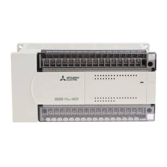
- Seite 50 FX2N Series Programmable Controllers Installation 3 Product outline Product outline Descrizione dell’apparecchio Description de l’appareil Descripción de las unidades Gerätebeschreibung ENG ☞ FRE ☞Description de l’API FX Figure 3.1: Features of the FX GER ☞ ☞ Descrizione dell’FX Beschreibung der FX -PLC ESP ☞...
- Seite 51 FX2N Series Programmable Controllers Installation 3 ENG ☞ Feature table FRE ☞ Vue d’ensemble des composants Table 3.1: GER ☞ Übersicht der Komponenten ☞ Componenti ESP ☞ Vista de conjunto de los componentes Barra DIN Carril de montaje DIN rail 35mm (1.37 Rail DIN (35 mm) selon DIN-Schiene (35mm) (35mm)secondo...
- Seite 52 FX2N Series Programmable Controllers Installation 3 RUN/STOP Control RUN/STOP Control RUN or STOP of the FX can be controlled by: ➀ The RUN/STOP switch mounted next to the programming port. ➁ A standard input (X0 to X17; X0 to X7 for FX -16M✩...
- Seite 53 FX2N Series Programmable Controllers Installation 3 Commande Run/Stop La fonction RUN ou STOP de la FX peut être commandée: ➀ au commutateur RUN/STOP installé à côté du port de programmation; ➁ au moyen d’une entrée standard (X0 à X17; X0 à X7 pour des unités FX -16M✩) définie par des paramètres système;...
- Seite 54 FX2N Series Programmable Controllers Installation 3 General specifications General specifications Specifica generale Caractéristiques générales Especificación general Umgebungsbedingungen ENG ☞ General specifications FRE ☞ Caractéristiques générales Table 3.3: GER ☞ Umgebungsbedingungen ☞ Specifica generale ESP ☞ Especificación general SPEC 0 - 55 °C Operating Température de Temperatura di...
- Seite 55 FX2N Series Programmable Controllers Installation 3 ENG ☞ General specifications FRE ☞ Caractéristiques générales Table 3.3: GER ☞ Umgebungsbedingungen ☞ Specifica generale ESP ☞ Especificación general SPEC Einsatzbereich bis For use up to an Utilisable jusqu’à Utilizzabile fino a Para un uso hasta <2000m zu einer Höhn von altitude of..
- Seite 56 FX2N Series Programmable Controllers Installation 3 PLC mounting arrangements PLC mounting arrangements Montage de l’API To prevent a rise in temperature, mount the units to Les appareils doivent être montés sur le panneau walls. Never mount them to the floor or ceiling of an arrière de l’armoire électrique pour empêcher une enclosure.
- Seite 57 FX2N Series Programmable Controllers Installation 3 Caution • Units should not be installed in areas subject to the following conditions: excessive or conductive dust, corrosive gas (salt air, Cl S, SO , NO , etc.) or flammable gas, moisture or rain, excessive heat, regular impact shocks or excessive vibration.
- Seite 58 FX2N Series Programmable Controllers Installation 3 Attention! • Les appareils ne doivent pas être installés dans les zones de travail dans lesquelles les conditions ambiantes suivantes peuvent se présenter: poussières excessives ou conductrices de courant, gaz corrosif (air du sel, Cl S, SO , NO , etc.) et gaz inflammable, humidité...
- Seite 59 FX2N Series Programmable Controllers Installation 3 Achtung • Die Geräte dürfen nicht in Arbeitsbereichen installiert werden, in denen die nachfolgenden Umgebungsbedingungen auftreten können: übermäßiger oder stromleitender Staub, zerstörendes Gas (Salzlnft, S, SO , NO , usw.) und feuergefährliches Gas, Nässe oder Regen, übermäßige Wärme, regelmäßige Aufprallstöße oder übermäßige Vibrationen.
- Seite 60 FX2N Series Programmable Controllers Installation 3 Attenzione • Gli apparecchi non devono essere installati in ambienti di lavoro in cui si possono riscontrare le seguenti condizioni ambientali: polvere eccessiva o conduttrice di corrente, benzina corrosiva (aria di sale, Cl S, SO , NO , ecc.) e benzina infiammabile, umidità...
- Seite 61 FX2N Series Programmable Controllers Installation 3 Atención • Las unidades no deben instalarse en zonas de trabajo, en las que se puedan presentar las condiciones ambientales siguientes: demasiado polvo o polvo conductivo, gas corrosivo (aire de sal, Cl S, SO , NO , etc.) y gas inflamble, humedad o lluvia, calor extremo, golpes de impacto regulares o vibraciones excesivas.
- Seite 62 FX2N Series Programmable Controllers Installation 3 DIN rail mounting DIN rail mounting Montage de l’appareil sur rail DIN Units can be ‘snap’ mounted on to 35mm (1.37 inch) L e s a p p a r e i l s p e u v e n t ê t r e m o n t é s “ p a r DIN rail.
- Seite 63 FX2N Series Programmable Controllers Installation 3 Direct mounting Direct mounting Montage direct -10GM and FX -20GM can only mount on the Le FX2N-10GM et le FX2N-20GM peuvent être DIN rail. montés seulement sur un rail DIN. Direkte Montage Montaggio diretto Das FX -10GM und das FX -20GM können nur...
- Seite 64 FX2N Series Programmable Controllers Installation 3 ☞Hole positions FRE ☞ Positions des trous Table 3.4: ☞Lochpositionen ☞ Posizioni dei fori ☞Posiciones de los agujeros inches UNIT ± 0.2 ± 0.01 D = W-8mm(0.32") -8AD 2.64 E = W-24.5mm(0.97") -232ADP, FX -485ADP 65.5 2.58...
- Seite 65 FX2N Series Programmable Controllers Installation 3 Extension Board Installation Extension Board Installation Installation de la carte d’extension To install a special function extension board on the Pour installer une car te d’extension à fonctions left side of the FX MPU: spéciales du côté...
- Seite 66 FX2N Series Programmable Controllers Installation 3 Figure 3.4: Instalación de la tarjeta de extensión3.8 Para instalar una tarjeta de extensión funcional especial en el lado izquierdo del FX MPU se debe: ➀ Quitar la tapa del FX ➁ Fijar tarjeta conector colocar correc tamen te sobre los agu jeros para...
- Seite 67 FX2N Series Programmable Controllers Installation 3 Extension Units/Blocks Installation Extension Units/Blocks Installation Installation d'extensions Install/remove extension module as shown in the Installez et désinstallez les appareils d'extension et figure 3.5. les modules spéciaux comme indiqué sur la Fig. 3.5 : ➀...
- Seite 68 FX2N Series Programmable Controllers Installation 3 MEMO 3-20...
- Seite 69 FX2N Series Programmable Controllers Wiring techniques 4 Wiring techniques Wiring techniques The wiring of FX products has been designed to be safe and easy. If during the installation of these product or associated products concern is felt, please contact a professional electrician who is trained to the local and national standards applicable to the installation site.
- Seite 70 FX2N Series Programmable Controllers Wiring techniques 4 Instructions relatives au cablage • Ne transmettez pas ensemble des signaux d’entrée et de sortie sur un même câble multiconducteur ou par la même ligne de signalisation. • Ne posez pas de câble de signalisation E/S à proximité de câbles de puissance ou dans un caniveau à câble commun.
- Seite 71 FX2N Series Programmable Controllers Wiring techniques 4 Avvertenze per il cablaggio • Non mettete insieme i segnali degli ingressi e delle uscite in un cavo multipolare o nella stessa linea di controllo. • Non posate i cavi dei segnali I/O in prossimità dei cavi di potenza o in una canalina comune. I cavi dibassa tensione devono essere separati o isolati in modo sicuro ai cavi di alta tensione.
- Seite 72 FX2N Series Programmable Controllers Wiring techniques 4 Termination at screw terminals Termination at screw terminals Terminal screws should be tightened to between 0.5 and 0.8 N·m. Terminal screws must be secured to prevent a loose connection thus avoiding a malfunction. The terminal screws for the FX Series PLC are M3.0.
- Seite 73 FX2N Series Programmable Controllers Wiring techniques 4 Achtung • Schalten Sie immer die Stromversorgung aus, bevor Sie mit den Verdrahtungsarbeiten beginnen. Allacciamento mediante morsetti a vite I morsetti avvitabili vengono montati con una coppia di 0,5 - 0,8 Nm. Se i morsetti avvitabili non sono ben serrati si possono verificare guasti di funzionamento.
- Seite 74 FX2N Series Programmable Controllers Wiring techniques 4 ENG ☞ Installing 1 wire per a Terminal Figure 4.3: Terminal Crimp ☞ Raccordement d'un fil sur une borne screw terminal GER ☞ Anschluss eines Drahtes an eine Klemme ☞ Collegamento di un filo ad un morsetto ☞...
- Seite 75 FX2N Series Programmable Controllers Wiring techniques 4 4.2.1 Removal and installation of quick-release terminal block Removal and installation of quick-release terminal block 4.2.1 Handling of quick-release terminal block • Removal: Loosen the left and right screws evenly. • Installation:Tighten the left and right screws evenly. Tightening torque 0.4 to 0.5 N•m Make sure that the center of the terminal block is not lifted.
- Seite 76 FX2N Series Programmable Controllers Wiring techniques 4 Desmontaje e instalación del bloque del terminal de desacoplamiento rápido 4.2.1 Manipulación del bloque del terminal de desacoplamiento rápido • Desmontaje:Afloje los tornillos de izquierda y derecha de manera equilibrada. • Instalación: Se aprietan los tornillos de la izquierda y derecha de manera equilibrada. Par de apriete de 0,4 a 0,5 N•m Tenga cuidado de que el centro del bloque de la terminal no se eleve.
- Seite 77 FX2N Series Programmable Controllers Wiring techniques 4 Power supply Power supply When wiring AC supplies the ‘Live’ cable should be connected to the ‘L’ terminal and the ‘Neutral’ cable should be connected to the ‘N’ terminal. When wiring DC supplies the ‘positive’ cable should be connected to the ‘+’ terminal and the negative cable should be connected to the ‘-’...
- Seite 78 FX2N Series Programmable Controllers Wiring techniques 4 Spannungsversorgung Beim Anschluß einer Wechselspannung (AC) müssen der L-Leiter an die L-Klemme und der N-Leiter an die N-Klemme angeschlossen werden. Beim Anschluß einer Gleichspannung (DC) müssen der positive Leiter an die (+)-Klemme und der negative Leiter an die (-)-Klemme angeschlossen werden.
- Seite 79 FX2N Series Programmable Controllers Wiring techniques 4 Alimentación de tensión Al conectar una tensión alterna (CA), los conductores L se tienen que conectar en la borna L y el conductor N en la borna N. En la conexión de una tensión continua (CC), el conductor positivo se tiene que conectar en la borna (+) y el conductor negativo en la borna (-).
- Seite 80 FX2N Series Programmable Controllers Wiring techniques 4 ENG ☞ Power requirements (all FX Table 4.1: -✩✩M/E type units) FRE ☞ Alimentation en tension (tous les appareils FX -✩✩M/E) GER ☞ Spannungsversorgung (alle FX -✩✩M/E-Geräte) ☞ Alimentazione della tensione (tutti gli apparecchi FX -✩✩M/E) ESP ☞...
- Seite 81 FX2N Series Programmable Controllers Wiring techniques 4 ENG ☞ Power connection diagram FRE ☞Raccordement de la tension Table 4.2: GER ☞ Spannungsanschluß ☞Allacciamento della tensione ESP ☞ Conexión de tensión Grounding Mise à la terre Erdung Terra Puesta a tierra (max.
- Seite 82 FX2N Series Programmable Controllers Wiring techniques 4 *1 It is recommended to use the same power source to power the MPU, input extension unit and special function blocks. If two sources are required, follow the below guidelines: - Supply power to the input extension blocks and special function blocks before or at the same time the main unit is powered.
- Seite 83 FX2N Series Programmable Controllers Wiring techniques 4 Earthing/Grounding Earthing/Grounding (AWG14) to ground equipment. Ground resistance must be less than 100 Ω. Note that the Use a cable at least 2mm ground cable must not be connected to the same ground as the power circuits. Mise à...
- Seite 84 FX2N Series Programmable Controllers Wiring techniques 4 Service power supply Service power supply If the system being installed uses the service supply from both the PLC and a powered extension block , then the 0V terminals should be linked. • DO NOT however, link the 24V terminals.
- Seite 85 FX2N Series Programmable Controllers Wiring techniques 4 ENG ☞ Service Supply (all FX Table 4.3: -✩✩M/E-ES/ESS type units) FRE ☞ Tension de service (tous les appareils FX -✩✩M/E-ES/ESS) GER ☞ Service-Spannung (alle FX -✩✩M/E-ES/ESSGeräte) ☞ Tensione di servizio (tutti gli apparecchi FX -✩✩M/E-ES/ESS) ESP ☞...
- Seite 86 FX2N Series Programmable Controllers Wiring techniques 4 MEMO 4-18...
- Seite 87 FX2N Series Programmable Controllers FX2N Series Programmable Controllers Inputs 5 Inputs Inputs Entrées Eingänge Ingressi Entradas 24V DC input specifications 24V DC input specifications Caractéristiques techniques des entrées pour 24 V CC Technische Daten der Eingänge Dati tecnici degli ingressi per 24 V für 24 V DC Datos técnicos de las entradas para 24 V CC...
- Seite 88 FX2N Series Programmable Controllers Inputs 5 5.1.1 Typical wiring Typical wiring 5.1.1 Exemple de câblage 5.1.1 Verdrahtungsbeispiel 5.1.1 Ejemplo de cableado 5.1.1 Esempio di cablaggio 5.1.1 ENG ☞ Source (positive input connection, negative S/S) Figure 5.1: ☞ Source (émetteur) (pôle positif) GER ☞...
- Seite 89 FX2N Series Programmable Controllers Inputs 5 ENG ☞ Item check FRE ☞ Description du poste Table 5.2: GER ☞ Positionsbeschreibung ☞ Descrizione della posizione ESP ☞ Descripción de posición REF. Tension de service DC-Service- Tensione di servizio Tensión de servicio ➊...
- Seite 90 FX2N Series Programmable Controllers Inputs 5 External supply Alimentation externe The example shown right, uses an external power L’exemple de droite montre l’utilisation d’une tension supply to activate the inputs de service externe pour activer les entrées. Externe Versorgung Alimentazione esterna Das rechte Beispiel zeigt den Einsatz einer externen L’esempio a destra indica l’impiego di una tensione di Versorgungsspannung zu Aktivierung der Eingänge.
- Seite 91 FX2N Series Programmable Controllers Inputs 5 5.1.4 Resistors and inputs connected in parallel Resistors and inputs connected in Résistance et entrée montées en parallel 5.1.4 parallèle 5.1.4 = 1 5 k Ω. U n e Parallel resistance Rp: FX = 15kΩ. If resistance Rp R é...
- Seite 92 FX2N Series Programmable Controllers Inputs 5 AC 110V Input, MPUs AC 110V Input, MPUs Appareils de base avec entrées 110V Grundgeräte mit AC 110V-Eingängen5.2 Apparecchi base con ingressi 110V Unidades bas con Entradas de 110V ENG ☞FX Table 5.3: -✩✩MR-UA1/UL input specification FRE ☞Caractéristiques des entrées FX -✩✩MR-UA1/UL GER ☞Kenndaten der FX...
- Seite 93 FX2N Series Programmable Controllers Inputs 5 5.2.1 110V AC input specifications 110V AC input specifications 5.2.1 Caractéristiques techniques des entrées pour 110 V CA 5.2.1 Technische Daten der Eingänge für AC 110 V 5.2.1 Dati tecnici degli ingressi per 110 V AC5.2.1 Datos técnicos de las entradas para 110 V 5.2.1...
- Seite 94 FX2N Series Programmable Controllers Inputs 5 5.2.2 Typical wiring Typical wiring 5.2.2 Exemple de câblage 5.2.2 Verdrahtungsbeispiel 5.2.2 Esempio di cablaggio 5.2.2 Ejemplo de cableado 5.2.2 ENG ☞ Typical wiring ☞ Exemple de câblage Figure 5.5: GER ☞ Verdrahtungsbeispiel ☞ Esempio di cablaggio ☞...
- Seite 95 FX2N Series Programmable Controllers Inputs 5 5.2.3 Programming caution Programming caution 5.2.3 Instructions relatives à la programmation 5.2.3 When using 110V AC units, high speed counter and Lorsque vous utilisez un appareil pour 110 V CA, interrupt routines are not suitable for use due to the n’utilisez ni le High-Speed-Counter (compteur grande long ‘ON/OFF’...
- Seite 96 FX2N Series Programmable Controllers Inputs 5 MEMO 5-10...
- Seite 97 FX2N Series Programmable Controllers Outputs 6 Outputs Outputs Sorties Ausgänge Uscite Salidas Relay output specification Relay output specification Caractéristiques techniques des sorties des relais Technische Daten der Relais-Ausgänge Dati tecnici delle uscite a relè Datos técnicos de las salidas de relé ENG ☞...
- Seite 98 FX2N Series Programmable Controllers Outputs 6 ENG ☞ FX Table 6.1: relay specification FRE☞Caractéristiques des relais FX GER ☞ Kenndaten der Relais, FX ITL ☞ Parametri dei relè, FX ESP ☞ Características de los relés, FX ∞ None Internal Output protection Protection interne de la sortie Aucune Interner Ausgangsschutz...
- Seite 99 FX2N Series Programmable Controllers Outputs 6 6.1.1 Product life of relay contacts Product life of relay contacts 6.1.1 The product life of relay contacts considerably varies depending on the load type used. Take care that loads generating reverse electromotive force or rush current may cause poor contact or deposition of contacts which may lead to considerable reduction of the contact product life.
- Seite 100 FX2N Series Programmable Controllers Outputs 6 Longévité des produits des contacts à relais 6.1.1 La longévité des produits des contacts à relais varie considérablement selon le type de charge utilisée. Prendre particulièrement garde à la force électromotrice de retour générant la charge ou à l’impulsion de courant qui peut être provoquée par un faible contact ou au dépôt de contacts produisant une diminution considérable de la longévité...