Extraflame FALO' 1CP Montageanweisungen
Verfügbare Sprachen
Verfügbare Sprachen
Quicklinks
AVVERTENZE
Prima di ogni accensione della macchina verifi care sempre che il braciere sia completamente libero
e pulito.
E' assolutamente vietato introdurre manualmente pellet all'interno del braciere.
All'interno della stufa si trovano 3 confezioni di sali disidratanti da rimuovere defi nitivamente prima
di accendere la stufa: 1 all'interno della camera di combustione, 2 all'esterno della stufa.
Per un ottimale funzionamento del prodotto, l'azienda invita l'utilizzatore a regolare l'affl usso del
pellet in base al tipo di combustibile utilizzato. Vedi sezione "Regolazione carico pellet" del libretto
istruzioni.
L'apparecchio deve funzionare alla potenza 4 o 5 per 2 o 3 giorni in modo tale che le parti meccaniche
abbiano la possibilità di assestarsi.
WARNING
Always check before lighting the stove that the burning pot is completely free and clean.
Do not insert pellet manually into the combustion pot.
3 packagings dehydrating salts will be found in the stove to be removed completely before starting
the heater: 1 inside the burning chamber, 2 on the outside.
For a correct functioning of this product, the manufacturer kindly asks the fi nal user to set the pellet
feeding according to the type of combustible. Please read the chapter "Pellet Feeding Adjustment"
in "Use and Maintenance Manual".
This stove must function at middle power (power 4 or 5) for 2 or 3 days in order to allow a better
settlement of the mechanical components.
ACHTUNG
Vor jeder Anzündung immer kontrollieren, dass die Brennschale frei und sauber ist.
Es ist verboten die Pellet in die Schale mit Händen zu werfen.
Im Pelletsofen sind 3 Packungen Trockensalz zu fi nden die anlässlich der Inbetriebnahme entfernt
werden müssen:1 in der Brennkamer und 2 sind ausserhalb des Ofens.
Zum dem optimalen Betrieb dieses Produktes bittet Der Hersteller den Benutzer darum, die
Pelletszufuhr gëmaβ dem verwendeten brennstoff einzustellen. Lesen Sie bitte den Paragraph
„Reglung der Pellets-Zufuhr" in der „Bedienungs- und Aufstellungsanleitung".
Das Gerät soll 2 oder 3 Tage auf Mittelleistung funktionieren (Stufe 4 oder 5) so dass die
mechanischeTeile sich einlaufen können.
ATTENTION
Avant d'allumer le poêle toujours contrôler que le brasier soit complètement libre et propre.
N'introduisez pas pellet manuellement dans le brasier.
A l'intérieur du poêle Vous retrouverez 3 paquets de sels déshydratants à enlever complètement ,
S.V.P., lors de la mise à feu : 1 dans le chambre de combustion, 2 à l'extérieur du poêle.
Pour un emploi optimal du produit, le producteur prie l'usager de bien vouloir régler le chargement
du pellet selon le type de combustible. Veuillez lire le paragraphe « Réglage charge Pellet » dans le
« Manuel d'instructions et entretien ».
L'appareil doit fonctionner à puissance 4 ou 5 pour 2 ou 3 jours, de façon que les parties mécaniques
puissent se tasser.
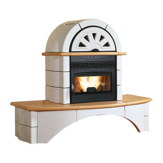
FALO' 1CP - 2CP

Verwandte Anleitungen für Extraflame FALO' 1CP


Inhaltszusammenfassung für Extraflame FALO' 1CP
- Seite 1 AVVERTENZE Prima di ogni accensione della macchina verifi care sempre che il braciere sia completamente libero e pulito. E’ assolutamente vietato introdurre manualmente pellet all’interno del braciere. All’interno della stufa si trovano 3 confezioni di sali disidratanti da rimuovere defi nitivamente prima di accendere la stufa: 1 all’interno della camera di combustione, 2 all’esterno della stufa.
- Seite 2 FALO’ 1CP - 2CP...
- Seite 4 Poêle à pellets modèle / Pelletofenmodell : Falò 1CP e Falò 2CP EN 14785 : 2006 Données Eigenschaften U.M. Poids Gewicht Hauteur Höhe 1522 Largeur Breite 1806 Profondeur Tiefe Diamètre tuyau évacuation fumées Durchmesser Rauchabzugsrohr Diamètre tuyau aspiration air Durchmesser Luftansaugrohr Volume de réchauff ement max Max.
-
Seite 20: Aufstellung Rauchentfernungsleitung
DEUTSCH MONTAGEANWEISUNGEN AUFSTELLUNG RAUCHENTFERNUNGSLEITUNG Für die Serie FALO’ wurden 2 Rauchentfernungssysteme vorgesehen, welche es gestatten, das eingekaufte Produkt den Kundenanforderungen anzupassen. Die vorgesehenen Systeme sind folgende: Hinterentfernung Oberentfernung (durch die Anwendung vom zusätzlichen Satz) Folgende Abbildung stellt die 2 möglichen Aufstellungsweisen dar. Sicherheitshintergitter. - Seite 21 DEUTSCH Schritt 2 S i d e profi le Den Ofenkörper an den Metallrahmen positionieren und Side profi le ihn durch die auf der Hinterseite der Struktur befi ndenden Schrauben befestigen. Die 2 seitlichen verzinkten Profi len mit den 4 im Kasten gelieferten Schrauben (SCHRAUBE AUT.TCB/C 4.2X9.5 BR) befestigen –...
- Seite 22 DEUTSCH Schritt 5 Die Mittelkachel (8) vor die Tür der Feuerung positionieren und dann die anderen Kacheln ganz einfach auf den Stützrahmen legen. (9 – 10 – 11 –12). Für die Befestigung wird es empfohlen einige Silicontropfen zu verwenden, dabei achten dass nicht zu viel Silicon verwendet wird, anderenfalls wird die eventuelle Entfernung der Teile schwierig.
- Seite 23 DEUTSCH Schritt 8 Nun die 2 voranmontierten Sätze durch Anwendung des vorher entfernten Stabs kuppeln. Schritt 9 Die 2 seitlichen Kacheln (G und H) positionieren und sie leicht durch die am Rahmen voreingestellten Schrauben und unrunden Scheiben anziehen. (Das herausragende Teil der Scheiben ist nach Außen zu richten, um das Lagern der Oberkacheln zu gewährleisten.) Das Mittelmajolikaelement (I) positionieren, indem man die seitlichen Elemente auf der...
- Seite 24 DEUTSCH Schritt 9 Schließlich das Vordermajolikaelement (P) positionieren und dabei die 3 schwarzen Platten und die 4 Befestigungsschrauben verwenden. 004275134 Fascicolo istruzioni Falò 1CP-2CP FALO’ 1CP - 2CP...