Hifonics NXi4002 Bedienungsanleitung
Class a/b
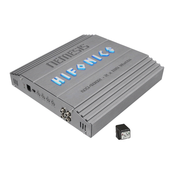
2-channel
amplifier nemesis series

Verwandte Anleitungen für Hifonics NXi4002


Inhaltszusammenfassung für Hifonics NXi4002
- Seite 1 BEDIENUNGSANLEITUNG USER’S MANUAL MODE D’EMPLOI MANUALE D’USO MANUAL DE USO CLASS A/B 2-CHANNEL AMPLIFIER NXi4002...
-
Seite 2: Inhaltsverzeichnis
INHALTSVERZEICHNIS TABLE OF CONTENT TABLE DES MATIÈRES SOMMARIO INDICE BEDIENUNGSANLEITUNG USER’S MANUAL MODE D’EMPLOI MANUALE D´USO MANUAL DE USO ABBILDUNGEN / FIGURES / FIGURES / FIGURE / FIGURES... -
Seite 3: Technische Daten
Bitte lesen Sie die Bedienungsanleitung vollständig durch, bevor Sie mit der Installation beginnen und den Verstärker in Betrieb nehmen. TECHNISCHE DATEN NXi4002 Ausgangsleistung RMS 2 x 100 W an 4 Ohm 2 x 180 W an 2 Ohm Ausgangsleistung Max. -
Seite 4: Anschlüsse
HINWEISE VOR DER INSTALLATION - Dieser Verstärker ist nur zum Betrieb in einem Fahrzeug geeignet. - Dieser Verstärker ist nur zum Anschluss an ein 12-Volt-System mit negativer Masse geeignet. - Die während des Betriebs abgestrahlte Wärme erfordert einen Montageort mit ausreichender Luftzirkulation. -
Seite 5: Lautsprecherverkabelung
LAUTSPRECHERVERKABELUNG Im 2-Kanal-Betrieb (d.h. je ein Lautsprecher pro Verstärkerkanal) sollte die Impedanz 2 Ohm pro Lautsprecher nicht unterschritten werden. Im gebrückten Modus (d.h. zwei Verstärkerausgänge werden zusammengeschaltet) verdoppelt sich die Mindest-Impedanz auf 4 Ohm pro gebrücktem Ausgang. Verbinden sie niemals die Lautsprecher-Anschlüsse mit der Masse des Fahrzeugchassis oder mit der +12 V Stromversorgung. -
Seite 6: Schutzschaltung
SCHUTZSCHALTUNG Die LED (POWER, Abb. 1, 1) leuchtet auf, wenn das Gerät betriebsbereit ist. Die LED (PROTECT, Abb. 1, 1) leuchtet auf, wenn das Gerät überhitzt ist, oder ein Kurzschluss bzw. eine zu geringe Impedanz an den Lautsprecheranschlüssen anliegt. Wenn dies eintritt, schaltet die integrierte Schutzschaltung den Verstärker automatisch aus und sollte nach Behebung des Problems wieder funktionieren. - Seite 7 FEHLERBEHEBUNG Falls Sie nach dem Einbau Probleme haben, befolgen Sie die nachfolgenden Verfahren zur Fehlerbeseitigung: Verfahren 1: Den Verstärker auf ordnungsgemäße Anschlüsse überprüfen. Prüfen Sie, ob die POWER-LED aufleuchtet. Leuchtet die POWER-LED auf, bei Schritt 3 weitermachen, falls nicht, hier weitermachen. 1.
- Seite 28 –...
- Seite 29 FULL 2 - 8 Ohms 2 - 8 Ohms...
- Seite 30 LP/BP 4 - 8 Ohms...