Herunterladen Diese Seite drucken

Werbung

Verfügbare Sprachen
  • DE

Verfügbare Sprachen

  • DEUTSCH, seite 3
EDK94AZRS6
.OdJ
L−force Drives
Montageanleitung
Mounting Instructions
Instructions de montage
Instrucciones para el montaje
Istruzioni per il montaggio
9400
54 ... 95 A
E94AZRS0544, E94AZRS0954
Funk−Entstörfilter
RFI filter
Filtre antiparasite
Filtro RFI
Filtro RFI
l

Werbung

loading

Inhaltszusammenfassung für Lenze E94AZRS0544

  • Seite 1 L−force Drives EDK94AZRS6 .OdJ Montageanleitung Mounting Instructions Instructions de montage Instrucciones para el montaje Istruzioni per il montaggio 9400 54 ... 95 A E94AZRS0544, E94AZRS0954 Funk−Entstörfilter RFI filter Filtre antiparasite Filtro RFI Filtro RFI...
  • Seite 2 Lesen Sie zuerst diese Anleitung und die Dokumentation zum Grundgerät, bevor Sie mit den Arbeiten beginnen! Beachten Sie die enthaltenen Sicherheitshinweise. Please read these instructions and the documentation of the standard device before you start working! Observe the safety instructions given therein! Lire le présent fascicule et la documentation relative à...
  • Seite 3 Inhalt Über diese Dokumentation ......... Informationen zur Gültigkeit .
  • Seite 4 Qualifiziertes Fachpersonal sind Personen, die für die auszuführenden Tätigkei- ten bei der Aufstellung, Montage, Inbetriebsetzung und dem Betrieb des Pro- dukts über entsprechende Qualifikationen verfügen. Tipp! Informationen und Hilfsmittel rund um die Lenze−Produkte finden Sie im Download−Bereich unter www.lenze.com EDK94AZRS6 DE/EN/FR/ES/IT 7.0...
  • Seite 5 Über diese Dokumentation Dokumenthistorie Dokumenthistorie Materialnummer Version Beschreibung .OdJ 09/2014 TD15 UL−Hinweise in französischer Sprache für Ca- nada EAC−Konformität allgemeine Korrekturen 13429260 04/2013 TD06 Überarbeitung 13348755 09/2010 TD29 Neuauflage wegen Neuorganisation des Un- ternehmens, Layout−Anpassung und Überar- beitung 13237063 02/2008 TD29 Überarbeitung 13218947...
  • Seite 6 Über diese Dokumentation Verwendete Hinweise Verwendete Hinweise Um auf Gefahren und wichtige Informationen hinzuweisen, werden in dieser Dokumentation folgende Piktogramme und Signalwörter verwendet: Sicherheitshinweise Aufbau der Sicherheitshinweise: Gefahr! (kennzeichnet die Art und die Schwere der Gefahr) Hinweistext (beschreibt die Gefahr und gibt Hinweise, wie sie vermieden werden kann) Piktogramm und Signalwort Bedeutung...
  • Seite 7 Über diese Dokumentation Verwendete Hinweise Spezielle Sicherheitshinweise und Anwendungshinweise Piktogramm und Signalwort Bedeutung Warnings! Sicherheitshinweis oder Anwendungshinweis für den Betrieb nach UL− oder CSA−Anforderungen. Die Maßnahmen sind erforderlich, um die Anforderun- gen nach UL oder CSA zu erfüllen. Warnings! EDK94AZRS6 DE/EN/FR/ES/IT 7.0...
  • Seite 8 Schaltungsausschnitte sind Vorschläge, deren Übertragbarkeit auf die jeweilige Anwendung überprüft werden muss. Für die Eignung der angege- benen Verfahren und Schaltungsvorschläge übernimmt der Hersteller keine Gewähr. Alle Arbeiten mit und an Lenze−Antriebs− und ƒ Automatisierungskomponenten darf nur qualifiziertes Fachpersonal ausführen.
  • Seite 9 Sicherheitshinweise Restgefahren Restgefahren Gefahr! Gefährliche elektrische Spannung Alle Leistungsanschlüsse führen bis zu 3 Minuten nach Netz−Ausschalten gefährliche elektrische Spannung. Mögliche Folgen: Tod oder schwere Verletzungen beim Berühren der ƒ Leistungsanschlüsse. Schutzmaßnahmen: Vor Arbeiten an den Leistungsanschlüssen Netz abschalten und ƒ mindestens 3 Minuten warten.
  • Seite 10 
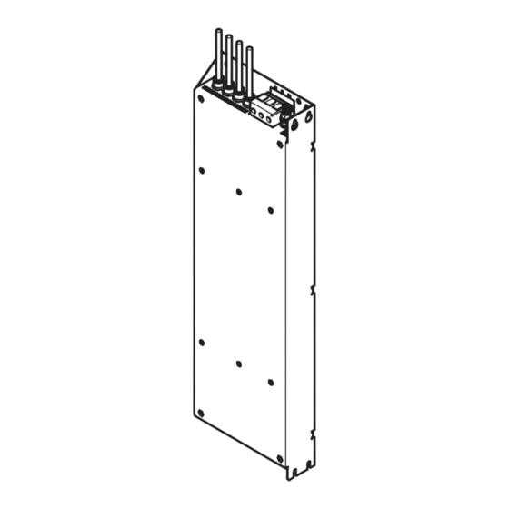
Produktbeschreibung Lieferumfang Produktbeschreibung Lieferumfang Pos. Beschreibung Funk−Entstörfilter E94AZRSxxxx Montageanleitung Übersicht SSP94FF601 Pos. Beschreibung PE−Anschluss (für Ring− oder Gabelkabelschuh M8) X301 Netzanschlussklemme L1 ... L3 X302 Anschlusskabel zum Antriebsregler 4−adrig Befestigungsgewinde für Grundgerät Typenschild Befestigung Standardmontage (Unterbau−Montage) Befestigung Montagevariante (Nebenbau−Montage) EDK94AZRS6 DE/EN/FR/ES/IT 7.0...
  • Seite 11 Die Verwendung dieses Filters ist zulässig mit Geräten der Produktreihe 9400 und i700 ab der Typenschildbezeichnung: E94ASxE032x E94ASxE047x E94ASxE059x 1.51 E94ASxE086x E94ASxE104x Zuordnung Filter ˘ Grundgerät Funk−Entstörfilter Einzelachsregler Gerätegröße Gerätegröße E94ASxE032x E94ASxE047x E94AZRS0544 E94ASxE059x E94ASxE086x E94AZRS0954 E94ASxE104x EDK94AZRS6 DE/EN/FR/ES/IT 7.0...
  • Seite 12 Technische Daten Allgemeine Daten und Einsatzbedingungen Technische Daten Allgemeine Daten und Einsatzbedingungen Konformität und Approbation Approbation UL508 Industrial Control Equipment, Underwriter Laborato- ries (File−No. E219022) for USA and Canada TP TC 020/2011 Elektromagnetische Eurasische Konformität Verträglichkeit von (TR ZU 020/2011) TR ZU: Technische Regulie- technischen Erzeugnis- rung der Zollunion...
  • Seite 13 Technische Daten Allgemeine Daten und Einsatzbedingungen Umweltbedingungen Klima Lagerung IEC/EN 60721−3−1 1K3 (−25 ... +60 °C) Transport IEC/EN 60721−3−2 2K3 (−25 ... +70 °C) Betrieb IEC/EN 60721−3−3 3K3 (−10 ... +55 °C) Stromreduzierung von +45 ... +55 °C: Gerätegröße 1 ... 7: 2.5 %/°C Gerätegröße 8S ...
  • Seite 14 400 − 0 % ... 550 + 0 % 45 − 0 % ... 65 + 0 % Spannung Frequenz Bemessungsstrom [A] Phasen- zahl bis +45 °C  bis +55 °C  [Hz] E94AZRS0544 230/400/500 50/60 54.0/54.0/54.0 40.5/40.5/40.5 E94AZRS0954 230/400/500 50/60 95.0/95.0/95.0 71.0/71.0/71.0 ...
  • Seite 15 Technische Daten Mechanische Daten Mechanische Daten SSP94FF602 Alle Maße in Millimeter. Masse [mm] [kg] E94AZxS 500 ±10 ...0544 13.0 550 ±10 ...0954 16.5 EDK94AZRS6 DE/EN/FR/ES/IT 7.0...
  • Seite 16 Mechanische Installation Wichtige Hinweise Mechanische Installation Wichtige Hinweise Der Montageort muss den in den Technischen Daten genannten ƒ Einsatzbedingungen immer entsprechen (¶ 12). Ggf. zusätzliche Maßnahmen ergreifen. Die Montageplatte des Schaltschranks muss folgende Eigenschaften ƒ aufweisen: – elektrisch leitfähig – lackfrei Die mechanischen Verbindungen müssen immer gewährleistet sein.
  • Seite 17 Mechanische Installation Standardmontage Bohrplan Standardmontage 5.2.1 Bohrplan SSP94FF608 Alle Maße in Millimeter. Grundgerät ohne Unterbaufilter Grundgerät mit Unterbaufilter Lochraster für Grundgerät ohne Unterbaufilter Lochraster für Grundgerät mit Unterbaufilter d (A) d (B) e (A) e (B) [mm] E94AZxS0544 E94AZxS0954 EDK94AZRS6 DE/EN/FR/ES/IT 7.0...
  • Seite 18 Mechanische Installation Standardmontage Montageschritte 5.2.2 Montageschritte SSP94FF603 So gehen Sie bei der Montage vor: 1. Bereiten Sie auf der Montageplatte M6−Gewindebohrungen vor und bestücken Sie diese mit Schrauben und Unterlegscheiben. – Vier M6−Kombischrauben oder M6−Innensechskantschrauben (Festigkeitsklasse 8.8) mit Unterlegscheiben. – Schrauben noch nicht ganz eindrehen.
  • Seite 19 Mechanische Installation Montagevariante Bohrplan Montagevariante 5.3.1 Bohrplan SSP94FF609 Alle Maße in Millimeter. Nebenbaufilter Grundgerät d (A) d (B) [mm] E94AZxS0544 E94AZxS0954 EDK94AZRS6 DE/EN/FR/ES/IT 7.0...
  • Seite 20 Mechanische Installation Montagevariante Montageschritte 5.3.2 Montageschritte SSP94FF604 So gehen Sie bei der Montage vor: 1. Bereiten Sie auf der Montageplatte Gewindebohrungen vor: – M6 für E94AZxS0544 – M8 für E94AZxS0954 2. Bestücken Sie diese mit Schrauben und Unterlegscheiben: – Für Filter und Grundgerät je vier Kombischrauben oder Innensechskantschrauben (Festigkeitsklasse 8.8) mit Unterlegscheiben.
  • Seite 21 Elektrische Installation Wichtige Hinweise Elektrische Installation Wichtige Hinweise Die Installation muss ƒ – den in den Technischen Daten genannten Einsatzbedingungen immer entsprechen (¶ 12). – nach EN 60204−1 ausgeführt werden. Bei der Auswahl des Leitungstyps beachten: ƒ – Die verwendeten Leitungen müssen den geforderten Approbationen am Einsatzort entsprechen (z.
  • Seite 22 Elektrische Installation Wichtige Hinweise Gefahr! Gefährliche elektrische Spannung Der Ableitstrom gegen Erde (PE) ist > 3.5 mA AC bzw. > 10 mA DC. Mögliche Folgen: Tod oder schwere Verletzungen beim Berühren des Gerätes im ƒ Fehlerfall. Schutzmaßnahmen: Die in der EN 61800−5−1 geforderten Maßnahmen umsetzen. Insbesondere: Festinstallation ƒ...
  • Seite 23 Elektrische Installation Anschlussplan Anschlussplan 1 (BK) F1...F3 2 (BK) 3 (BK) PE (GN/YE) X302 X301 X100 E94AZxSxxxx E94ASxExxxxx SSP94FF610 EDK94AZRS6 DE/EN/FR/ES/IT 7.0...
  • Seite 24 Elektrische Installation Anschlussdaten Anschlussdaten Netz Klemme X301 Beschriftung Beschreibung Anschluss der Netzphasen L1, L2, L3 Anschluss für den netzseitigen Schutzleiter mit Ringkabel- schuh M8 SSP94FF606 Klemmendaten max. Leiterquerschnitt Anzugsmoment [AWG] [Nm] [lb−in] E94AZxS0544 88.5 Inbus 5 E94AZxS0954 124.0 PE−Anschlussdaten Æ Anzugsmoment [mm] [Nm]...
  • Seite 25 Contents About this documentation ......... . Validity information .
  • Seite 26 Qualified skilled personnel are persons who have the required qualifications to carry out all activities involved in installing, mounting, commissioning, and operating the product. Tip! Information and tools concerning the Lenze products can be found in the download area under www.lenze.com Document history...
  • Seite 27 About this documentation Conventions used Conventions used Type of information Identification Examples/notes Spelling of numbers Decimal separator Point In general, the decimal point is used. For instance: 1234.56 Warnings UL warnings Given in English and French UR warnings Text Program name »...
  • Seite 28 About this documentation Notes used Notes used The following pictographs and signal words are used in this documentation to indicate dangers and important information: Safety instructions Structure of safety instructions: Danger! (characterises the type and severity of danger) Note (describes the danger and gives information about how to prevent dangerous situations) Pictograph and signal word Meaning...
  • Seite 29 About this documentation Notes used Special safety instructions and application notes Pictograph and signal word Meaning Warnings! Safety note or application note for the operation according to UL or CSA requirements. The measures are required to meet the requirements according to UL or CSA. Warnings! EDK94AZRS6 DE/EN/FR/ES/IT 7.0...
  • Seite 30 The manufacturer does not accept any liability for the suitability of the specified procedures and circuit proposals. Only qualified skilled personnel are permitted to work with or on Lenze ƒ drive and automation components.
  • Seite 31 Safety instructions Residual hazards Residual hazards Danger! Dangerous electrical voltage All power terminals remain live for up to three minutes after mains disconnection. Possible consequences: Death or severe injuries when touching the power terminals. ƒ Protective measures: Switch off the power supply and wait for at least three minutes ƒ...
  • Seite 32 Product description Scope of supply Product description Scope of supply Pos. Description RFI filter E94AZRSxxxx Mounting Instructions Overview SSP94FF601 Pos. Description PE connection (for ring or fork−type cable lug M8) X301 Mains terminal L1 ... L3 X302 Connection cable to controller, four−core Fastening thread for standard device Nameplate Fixings for standard mounting (footprint mounting)
  • Seite 33 The use of this filter is permissible with devices of the 9400 and i700 product ranges starting from nameplate data: E94ASxE032x E94ASxE047x E94ASxE059x 1.51 E94ASxE086x E94ASxE104x Assignment of filters to standard devices RFI filter Single−axis controller Type Device size Type Device size E94ASxE032x E94ASxE047x E94AZRS0544 E94ASxE059x E94ASxE086x E94AZRS0954 E94ASxE104x EDK94AZRS6 DE/EN/FR/ES/IT 7.0...
  • Seite 34 Technical data General data and operating conditions Technical data General data and operating conditions Conformity and approval Approval UL508 Industrial Control Equipment, Underwriter Laboratories (File−No. E219022) for USA and Canada TP TC 020/2011 Electromagnetic Eurasian Conformity compatibility of (TR CU 020/2011) TR CU: Technical Regulation technical means of Customs Union...
  • Seite 35 Technical data General data and operating conditions Environmental conditions Climate Storage IEC/EN 60721−3−1 1K3 (−25 ... +60 °C) Transport IEC/EN 60721−3−2 2K3 (−25 ... +70 °C) Operation IEC/EN 60721−3−3 3K3 (−10 ... +55 °C) Current derating at +45 ... +55 °C: Device size 1 ...
  • Seite 36 400 − 0 % ... 550 + 0 % 45 − 0 % ... 65 + 0 % Voltage Frequency Rated current [A] Number of phases up to +45 °C  up to +55 °C  [Hz] E94AZRS0544 230/400/500 50/60 54.0/54.0/54.0 40.5/40.5/40.5 E94AZRS0954 230/400/500 50/60 95.0/95.0/95.0 71.0/71.0/71.0 ...
  • Seite 37 Technical data Mechanical data Mechanical data SSP94FF602 All dimensions in millimetres. Mass [mm] [kg] E94AZxS 500 ±10 ...0544 13.0 550 ±10 ...0954 16.5 EDK94AZRS6 DE/EN/FR/ES/IT 7.0...
  • Seite 38 Mechanical installation Important notes Mechanical installation Important notes The mounting location must always comply with the operating conditions ƒ specified in the technical data (¶ 34). Take additional measures if necessary. The mounting plate of the control cabinet must have the following ƒ...
  • Seite 39 Mechanical installation Standard mounting Drilling pattern Standard mounting 5.2.1 Drilling pattern SSP94FF608 All dimensions in millimetres. Standard device without footprint filter Standard device with footprint filter Hole pattern for standard device without footprint filter Hole pattern for standard device with footprint filter d (A) d (B) e (A)
  • Seite 40 Mechanical installation Standard mounting Mounting steps 5.2.2 Mounting steps SSP94FF603 Proceed as follows for the installation: 1. Drill M6 threaded holes in the mounting plate and attach screws and washers. – Four M6 screw and washer assemblies or M6 hexagon socket screws (property class 8.8) with washers.
  • Seite 41 Mechanical installation Mounting variant Drilling pattern Mounting variant 5.3.1 Drilling pattern SSP94FF609 All dimensions in millimetres. Side−by−side filter Standard device d (A) d (B) [mm] E94AZxS0544 E94AZxS0954 EDK94AZRS6 DE/EN/FR/ES/IT 7.0...
  • Seite 42 Mechanical installation Mounting variant Mounting steps 5.3.2 Mounting steps SSP94FF604 How to proceed during the mounting process: 1. Prepare threaded holes on the mounting plate: – M6 for E94AZxS0544 – M8 for E94AZxS0954 2. Assemble the threaded holes with screws and washers: –...
  • Seite 43 Electrical installation Important notes Electrical installation Important notes Installation must ƒ – always be in accordance with the operating conditions specified in the Technical data (¶ 34). – be carried out to EN 60204−1. Please observe the following when selecting the cable type: ƒ...
  • Seite 44 Electrical installation Important notes Danger! Hazardous electrical voltage The leakage current to earth (PE) is > 3.5 mA AC or > 10 mA DC. Possible consequences: Death or severe injuries when touching the device in the event of ƒ an error. Protective measures: Implement the measures required in EN 61800−5−1.
  • Seite 45 Electrical installation Connection plan Connection plan 1 (BK) F1...F3 2 (BK) 3 (BK) PE (GN/YE) X302 X301 X100 E94AZxSxxxx E94ASxExxxxx SSP94FF610 EDK94AZRS6 DE/EN/FR/ES/IT 7.0...
  • Seite 46 Electrical installation Connection data Connection data Mains Terminal X301 Labelling Description Connection of the mains phases L1, L2, L3 Connection for the supply−side PE conductor with ring cable lug M8 SSP94FF606 Terminal data Max. conductor cross−section Tightening torque [AWG] [Nm] [lb−in] E94AZxS0544 88.5...
  • Seite 47 Sommaire Présentation du document ......... Validité...
  • Seite 48 à leurs activités. Conseil ! Toutes les informations relatives aux produits Lenze peuvent être téléchargées sur notre site à l’adresse suivante : www.Lenze.com Historique du document Numéro de document Version...
  • Seite 49 Présentation du document Conventions utilisées Conventions utilisées Type d’information Aperçu Exemples/remarques Représentation des chiffres Séparateur décimal Point Le point décimal est généralement utilisé. Exemple : 1234.56 Consignes préventives Consignes préventives UL En anglais et en français Consignes préventives UR Mise en évidence de textes spéciaux Nom de programme »...
  • Seite 50 Présentation du document Consignes utilisées Consignes utilisées Pour indiquer des risques et des informations importantes, la présente documentation utilise les mots et pictogrammes suivants : Consignes de sécurité Présentation des consignes de sécurité Danger ! (Le pictogramme indique le type de risque.) Explication (L’explication décrit le risque et les moyens de l’éviter.) Pictogramme et mot associé...
  • Seite 51 Présentation du document Consignes utilisées Consignes de sécurité et d’utilisation spéciales Pictogramme et mot associé Description Avertissements ! Consigne de sécurité ou d’utilisation pour le fonctionnement selon les normes UL ou CSA. Les mesures sont requises pour répondre aux exigences des normes UL ou CSA.
  • Seite 52 Les procédures à suivre et les plans de raccordement fournis constituent des recommandations dont l’adéquation avec l’application concernée doit être vérifiée. Lenze n’assumera aucune responsabilité pour les dommages liés à un problème d’adéquation des procédures et plans de raccordements indiqués.
  • Seite 53 Consignes de sécurité Dangers résiduels Dangers résiduels Danger ! Tension électrique dangereuse Les raccordements de puissance sont encore sous tension jusqu’à 3 minutes après la coupure réseau. Risques encourus : Mort ou blessures graves en cas de contact accidentel avec les ƒ...
  • Seite 54 Description du produit Equipement livré Description du produit Equipement livré Pos. Description Filtre antiparasite E94AZRSxxxx. Instructions de montage Présentation générale SSP94FF601 Pos. Description Raccordement PE (pour cosse de câble circulaire ou à fourche M8) X301 Borne de raccordement au réseau L1 ... L3 X302 Câble de raccordement au variateur à...
  • Seite 55 (voir plaque signalétique) : E94ASxE032x E94ASxE047x E94ASxE059x 1.51 E94ASxE086x E94ASxE104x Combinaisons entre les filtres et les appareils de base Filtre antiparasite Variateur mono−axe Type Taille Type Taille E94ASxE032x E94ASxE047x E94AZRS0544 E94ASxE059x E94ASxE086x E94AZRS0954 E94ASxE104x EDK94AZRS6 DE/EN/FR/ES/IT 7.0...
  • Seite 56 Spécifications techniques Caractéristiques générales et conditions d’utilisation Spécifications techniques Caractéristiques générales et conditions d’utilisation Conformité et homologation Homologation UL508 Industrial Control Equipment, Underwriter Laboratories (File−No. E219022) for USA and Canada TP TC 020/2011 Compatibilité Conformité eurasienne électromagnétique des (RT UD 020/2011) RT UD : Règlement équipements technique de l’Union...
  • Seite 57 Spécifications techniques Caractéristiques générales et conditions d’utilisation Conditions climatiques Classification climatique Stockage CEI/EN 60721−3−1 1K3 (−25 ... +60 °C) Transport CEI/EN 60721−3−2 2K3 (−25 ... +70 °C) Fonctionnement CEI/EN 60721−3−3 3K3 (−10 ... +55 °C) Réduction de courant de +45 ... +55 °C : Taille d’appareil 1 ...
  • Seite 58 400 − 0 % ... 550 + 0 % 45 − 0 % ... 65 + 0 % Tension Fréquence Courant assigné [A] Nombre de phases +45 °C max.  +55 °C max.  [Hz] E94AZRS0544 230/400/500 50/60 54.0/54.0/54.0 40.5/40.5/40.5 E94AZRS0954 230/400/500 50/60 95.0/95.0/95.0 71.0/71.0/71.0 ...
  • Seite 59 Spécifications techniques Caractéristiques mécaniques Caractéristiques mécaniques SSP94FF602 Cotes en [mm] Poids [mm] [kg] E94AZxS 500 ±10 ...0544 13.0 550 ±10 ...0954 16.5 EDK94AZRS6 DE/EN/FR/ES/IT 7.0...
  • Seite 60 Installation mécanique Remarques importantes Installation mécanique Remarques importantes L’emplacement de montage doit impérativement remplir les conditions ƒ d’utilisation décrites dans les spécifications techniques.(¶ 56). Si nécessaire, prendre des mesures complémentaires. La plaque de montage de l’armoire électrique doit présenter les ƒ...
  • Seite 61 Installation mécanique Montage standard Plan de perçage Montage standard 5.2.1 Plan de perçage SSP94FF608 Cotes en [mm] Appareil de base sans filtre montage arrière Appareil de base avec filtre montage arrière Grille perforée pour appareil de base sans filtre montage arrière Grille perforée pour appareil de base avec filtre montage arrière d (A) d (B)
  • Seite 62 Installation mécanique Montage standard Opérations de montage 5.2.2 Opérations de montage SSP94FF603 Procédure de montage : 1. Sur la plaque de montage, préparer les trous taraudés M6 et y placer les vis et les rondelles. – Prévoir quatre boulons avec rondelle incorporée M6 ou quatre vis à six pans creux M6 (classe de résistance 8.8) avec rondelles.
  • Seite 63 Installation mécanique Variante de montage Plan de perçage Variante de montage 5.3.1 Plan de perçage SSP94FF609 Cotes en [mm] Filtre latéral Appareil de base d (A) d (B) [mm] E94AZxS0544 E94AZxS0954 EDK94AZRS6 DE/EN/FR/ES/IT 7.0...
  • Seite 64 Installation mécanique Variante de montage Opérations de montage 5.3.2 Opérations de montage SSP94FF604 Procédure de montage : 1. Préparer les trous taraudés sur la plaque de montage : – M6 pour E94AZxS0544 – M8 pour E94AZxS0954 2. Y placer les vis et les rondelles : –...
  • Seite 65 Installation électrique Remarques importantes Installation électrique Remarques importantes L’installation doit ƒ – toujours respecter les conditions d’utilisation indiquées dans les spécifications techniques (¶ 56) ; – répondre aux exigences de la norme EN 60204−1. Lors du choix du type de câble, tenir compte des points suivants : ƒ...
  • Seite 66 Installation électrique Remarques importantes Danger ! Tension électrique dangereuse Le courant de fuite vers la terre (PE) est > 3.5 mA CA ou > 10 mA CC. Risques encourus : Mort ou blessures graves en cas de contact accidentel avec ƒ...
  • Seite 67 Installation électrique Schéma de câblage Schéma de câblage 1 (BK) F1...F3 2 (BK) 3 (BK) PE (GN/YE) X302 X301 X100 E94AZxSxxxx E94ASxExxxxx SSP94FF610 EDK94AZRS6 DE/EN/FR/ES/IT 7.0...
  • Seite 68 Installation électrique Données de raccordement Données de raccordement Réseau d’alimentation Bornier X301 Marquage Description Raccordement des phases réseau L1, L2, L3 Raccordement du conducteur de protection côté réseau avec cosse de câble circulaire M8 SSP94FF606 Spécifications pour bornier Section max. de câble Couple de serrage [AWG] [Nm]...
  • Seite 69 Installation électrique Opérations de montage Opérations de montage Procédure de raccordement du filtre : 1. Brancher le câble de sortie du filtre (X302) sur la borne X100 de l’appareil de base. 2. Brancher le câble réseau sur la borne X301. 3.
  • Seite 70 Installation électrique EDK94AZRS6 DE/EN/FR/ES/IT 7.0...
  • Seite 71 Sommario Informazioni sul manuale ......... . Informazioni sulla validità...
  • Seite 72 Per personale tecnico qualificato si intendono persone dotate delle necessarie qualifiche per lo svolgimento delle attività di preparazione, montaggio, messa in servizio e funzionamento del prodotto. Suggerimento: Per informazioni e ausili sui prodotti Lenze, consultare l’area Download all’indirizzo www.lenze.com Cronologia del documento...
  • Seite 73 Informazioni sul manuale Convenzioni utilizzate Convenzioni utilizzate Tipo di informazione Convenzione Esempi/Note tipografica Modalità di scrittura dei numeri Separatore decimali Punto Si utilizza in generale il punto come separatore dei decimali. Esempio: 1234.56 Avvertenze Avvertenze UL Vengono riportate in inglese e francese.
  • Seite 74 Informazioni sul manuale Avvertenze utilizzate Avvertenze utilizzate segnalare pericoli informazioni importanti, nella presente documentazione sono riportati i seguenti simboli e parole di segnalazione: Note di sicurezza Struttura delle note di sicurezza: Pericolo! (indica il tipo e la gravità del pericolo) Testo della nota (descrive il pericolo e fornisce indicazioni su come può...
  • Seite 75 Informazioni sul manuale Avvertenze utilizzate Note di sicurezza e istruzioni d’uso speciali Simbolo e parola di segnalazione Significato Warnings! Nota di sicurezza o istruzioni d’uso per il funzionamento secondo i requisiti UL o CSA. Le misure sono necessarie per soddisfare i requisiti della normativa UL o CSA.
  • Seite 76 Note generali di sicurezza Pericolo! La mancata osservanza delle seguenti misure fondamentali di sicurezza può provocare gravi danni a persone e cose. Relativamente ai componenti di azionamento e automazione Lenze, ƒ osservare quanto segue: utilizzare tali componenti esclusivamente in conformità agli usi preposti...
  • Seite 77 Informazioni sulla sicurezza Altri pericoli Altri pericoli Pericolo! Tensione elettrica pericolosa Tutti i collegamenti di potenza presentano una tensione elettrica pericolosa fino a 3 minuti dopo la disinserzione dalla rete. Possibili conseguenze: Morte o gravi lesioni in caso di contatto con i collegamenti di ƒ...
  • Seite 78 Descrizione del prodotto Oggetto della fornitura Descrizione del prodotto Oggetto della fornitura Pos. Descrizione Filtro RFI E94AZRSxxxx Istruzioni di montaggio Panoramica SSP94FF601 Pos. Descrizione Collegamento PE (per capocorda ad anello o a forchetta M8) X301 Morsettiera di collegamento alla rete L1 ... L3 X302 Cavo di collegamento all’unità...
  • Seite 79 L’utilizzo di questo filtro è consentito con dispositivi della serie 9400 e i700 a partire dalle versioni seguenti: E94ASxE032x E94ASxE047x E94ASxE059x 1.51 E94ASxE086x E94ASxE104x Abbinamento filtro / modulo Filtro RFI Modulo monoasse Tipo Taglia Tipo Taglia E94ASxE032x E94ASxE047x E94AZRS0544 E94ASxE059x E94ASxE086x E94AZRS0954 E94ASxE104x EDK94AZRS6 DE/EN/FR/ES/IT 7.0...
  • Seite 80 Dati tecnici Dati generali e condizioni di impiego Dati tecnici Dati generali e condizioni di impiego Conformità e omologazione Omologazione UL508 Industrial Control Equipment, Underwriter Laboratories (File−No. E219022) for USA and Canada TP TC 020/2011 Compatibilità Conformità euroasiatica elettromagnetica degli (TR ZU 020/2011) TR ZU: Regolamento tecnico apparecchi tecnici...
  • Seite 81 Dati tecnici Dati generali e condizioni di impiego Condizioni ambientali Clima Stoccaggio IEC/EN 60721−3−1 1K3 (−25 ... +60 °C) Trasporto IEC/EN 60721−3−2 2K3 (−25 ... +70 °C) Funzionamento IEC/EN 60721−3−3 3K3 (−10 ... +55 °C) Riduzione di corrente da +45 a +55 °C: Taglia 1 ...
  • Seite 82 400 − 0 % ... 550 + 0 % 45 − 0 % ... 65 + 0 % Tensione Frequenza Corrente nominale [A] Numero di fasi fino a +45 °C  fino a +55 °C  [Hz] E94AZRS0544 230/400/500 50/60 54.0/54.0/54.0 40.5/40.5/40.5 E94AZRS0954 230/400/500 50/60 95.0/95.0/95.0 71.0/71.0/71.0 ...
  • Seite 83 Dati tecnici Dati meccanici Dati meccanici SSP94FF602 Tutte le quote sono in millimetri. Mass [mm] [kg] E94AZxS 500 ±10 ...0544 13.0 550 ±10 ...0954 16.5 EDK94AZRS6 DE/EN/FR/ES/IT 7.0...
  • Seite 84 Installazione meccanica Note importanti Installazione meccanica Note importanti Il luogo di montaggio deve essere sempre conforme alle condizioni di ƒ impiego riportate nei dati tecnici (¶ 80). Se necessario, adottare misure aggiuntive. La piastra di montaggio dell’armadio elettrico deve presentare le seguenti ƒ...
  • Seite 85 Installazione meccanica Montaggio standard Schema di foratura Montaggio standard 5.2.1 Schema di foratura SSP94FF608 Tutte le quote sono in millimetri. Modulo asse senza filtro montato sotto Modulo asse con filtro montato sotto Griglia con fori per modulo asse senza filtro montato sotto Griglia con fori per modulo asse con filtro montato sotto d (A) d (B)
  • Seite 86 Installazione meccanica Montaggio standard Procedura di montaggio 5.2.2 Procedura di montaggio SSP94FF603 Per il montaggio, procedere come segue: 1. Eseguire i fori filettati M6 sulla piastra di montaggio ed inserire le viti e le rondelle. – Utilizzare quattro viti con rondella M6 o viti ad esagono M6 (classe di resistenza 8.8) con rondella.
  • Seite 87 Installazione meccanica Variante di montaggio Schema di foratura Variante di montaggio 5.3.1 Schema di foratura SSP94FF609 Tutte le quote sono in millimetri. Filtro montato a lato Inverter d (A) d (B) [mm] E94AZxS0544 E94AZxS0954 EDK94AZRS6 DE/EN/FR/ES/IT 7.0...
  • Seite 88 Installazione meccanica Variante di montaggio Procedura di montaggio 5.3.2 Procedura di montaggio SSP94FF604 Per il montaggio, procedere come segue: 1. Sulla piastra di montaggio eseguire i seguenti fori filettati: – M6 per E94AZxS0544 – M8 per E94AZxS0954 2. Inserire le viti e le rondelle: –...
  • Seite 89 Installazione elettrica Note importanti Installazione elettrica Note importanti L’installazione deve ƒ – essere sempre conforme alle condizioni di impiego riportate nei dati tecnici (¶ 80). – essere eseguita secondo la normativa EN 60204−1. Nella selezione del tipo di cavo osservare quanto segue: ƒ...
  • Seite 90 Installazione elettrica Note importanti Pericolo! Tensione elettrica pericolosa La corrente dispersa verso terra (PE) è > 3,5 mA AC o > 10 mA DC. Possibili conseguenze: Morte o gravi lesioni in seguito a contatto del dispositivo in caso ƒ di guasto. Misure di protezione: Applicare le misure richieste secondo la norma EN 61800−5−1.
  • Seite 91 Installazione elettrica Schema di collegamento Schema di collegamento 1 (BK) F1...F3 2 (BK) 3 (BK) PE (GN/YE) X302 X301 X100 E94AZxSxxxx E94ASxExxxxx SSP94FF610 EDK94AZRS6 DE/EN/FR/ES/IT 7.0...
  • Seite 92 Installazione elettrica Dati di collegamento Dati di collegamento Rete Morsettiera X301 Siglatura Descrizione Collegamento delle fasi di alimentazione L1, L2, L3 Connessione per il conduttore di protezione (PE) con terminale ad anello M8 SSP94FF606 Dati dei morsetti Sezione max. conduttore Coppia di serraggio [AWG] [Nm]...
  • Seite 93 Installazione elettrica Procedura di montaggio Procedura di montaggio Per collegare il filtro, procedere come segue: 1. Collegare il cavo di uscita del filtro (X302) alla morsettiera X100 sul dispositivo base. 2. Collegare il cavo di rete alla morsettiera X301. 3. Collegare il conduttore di protezione PE sul lato della rete con capocorda a forchetta o ad anello sulla vite PE.
  • Seite 94 Installazione elettrica EDK94AZRS6 DE/EN/FR/ES/IT 7.0...
  • Seite 95 Contenido Acerca de esta documentación ........Información sobre la validez .
  • Seite 96 Personal experto cualificado son aquellas personas que disponen de las cualificaciones adecuadas para realizar los trabajos necesarios para la instalación, montaje, puesta en marcha y operación del producto. ¡Sugerencia! Encontrará información y consejos sobre los productos de Lenze en el área de descargas en www.lenze.com Historia del documento Nº...
  • Seite 97 Acerca de esta documentación Convenciones utilizadas Convenciones utilizadas Tipo de información Marcación Ejemplos/indicaciones Escritura de números Separación de decimales Punto Por norma general se utiliza el punto para los decimales. Por ejemplo: 1234.56 Advertencias Advertencias UL Se utilizan en Inglés y Francés. Advertencias UR Resalte del texto Nombre del programa...
  • Seite 98 Acerca de esta documentación Indicaciones utilizadas Indicaciones utilizadas Para indicar peligros e información importante, se utilizan en esta documentación los siguientes términos indicativos y símbolos: Instrucciones de seguridad Estructura de las instrucciones de seguridad: ¡Peligro! (indican el tipo y la gravedad del peligro) Texto indicativo (describe el peligro y da instrucciones para evitarlo) Pictograma y término indicativo...
  • Seite 99 Todos los trabajos con y en componentes de accionamiento y ƒ automatización de Lenze sólo deben ser realizados por personal experto cualificado. Según IEC 60364 o resp. CENELEC HD 384 se trata de personas, ..que conocen la instalación, el montaje, la puesta en marcha y la operación del producto.
  • Seite 100 Instrucciones de seguridad Peligros residuales Peligros residuales ¡Peligro! Tensión eléctrica peligrosa Todas las conexiones de potencia conducen una tensión eléctrica peligrosa tras la desconexión de la red durante 3 minutos. Posibles consecuencias: Muerte o lesiones peligrosas al entrar en contacto con las ƒ...
  • Seite 101 Descripción del producto Alcance del suministro Descripción del producto Alcance del suministro Pos. Descripción Filtro RFI E94AZRSxxxx Instrucciones para el montaje Vista general SSP94FF601 Pos. Descripción Conexión PE (para terminal anular o de horquilla M8) X301 Borne de conexión a red L1 ... L3 X302 Cable de conexión hacia el convertidor, 4 conductores Rosca de sujeción para equipo básico...
  • Seite 102 E94ASxE032x E94ASxE047x E94ASxE059x 1.51 E94ASxE086x E94ASxE104x Asignación filtro / equipo básico Filtro RFI Controlador monoeje Tipo Tamaño del equipo Tipo Tamaño del equipo E94ASxE032x E94ASxE047x E94AZRS0544 E94ASxE059x E94ASxE086x E94AZRS0954 E94ASxE104x EDK94AZRS6 DE/EN/FR/ES/IT 7.0...
  • Seite 103 Datos técnicos Datos generales y condiciones de uso Datos técnicos Datos generales y condiciones de uso Conformidad y aprobaciones Approbación UL508 Industrial Control Equipment, Underwriter Laboratories (File−No. E219022) for USA and Canada TP TC 020/2011 Compatibilidad Conformidad Eurasiática electromagnética de (TR TS 020/2011) TR TS: Reglamento Técnico productos técnicos...
  • Seite 104 Datos técnicos Datos generales y condiciones de uso Condiciones ambientales Clima Almacenaje IEC/EN 60721−3−1 1K3 (−25 ... +60 °C) Transporte IEC/EN 60721−3−2 2K3 (−25 ... +70 °C) Funcionamiento IEC/EN 60721−3−3 3K3 (−10 ... +55 °C) Reducción de corriente de +45 ... +55 °C: Tamaño del equipo 1 ...
  • Seite 105 400 − 0 % ... 550 + 0 % 45 − 0 % ... 65 + 0 % Voltaje Frecuencia Corriente nominal [A] Número de fases hasta +45 °C  hasta +55 °C  [Hz] E94AZRS0544 230/400/500 50/60 54.0/54.0/54.0 40.5/40.5/40.5 E94AZRS0954 230/400/500 50/60 95.0/95.0/95.0 71.0/71.0/71.0 ...
  • Seite 106 Datos técnicos Datos mecánicos Datos mecánicos SSP94FF602 Todas las medidas en milímetros. Medi [mm] [kg] E94AZxS 500 ±10 ...0544 13.0 550 ±10 ...0954 16.5 EDK94AZRS6 DE/EN/FR/ES/IT 7.0...
  • Seite 107 Instalación mecánica Indicaciones importantes Instalación mecánica Indicaciones importantes El lugar de montaje deberá corresponder siempre a las condiciones de uso ƒ indicadas en las características técnicas (¶ 103). en su caso tomar las medidas oportunas. La placa de montaje del armario de maniobra deberá cumplir con las ƒ...
  • Seite 108 Instalación mecánica Montaje estándar Plano de perforación Montaje estándar 5.2.1 Plano de perforación SSP94FF608 Todas las medidas en milímetros. Equipo básico sin filtro inferior Equipo básico con filtro inferior Plantilla de taladros para equipo básico sin filtro inferior Plantilla de taladros para equipo básico con filtro inferior d (A) d (B) e (A)
  • Seite 109 Instalación mecánica Montaje estándar Pasos para el montaje 5.2.2 Pasos para el montaje SSP94FF603 Para el montaje, proceda de la siguiente manera: 1. Prepare en la placa de montaje los taladros roscados M6 y coloque en ellos tornillos y arandelas. –...
  • Seite 110 Instalación mecánica Variante de montaje Plano de perforación Variante de montaje 5.3.1 Plano de perforación SSP94FF609 Todas las medidas en milímetros. Filtro de montaje lateral Equipo básico d (A) d (B) [mm] E94AZxS0544 E94AZxS0954 EDK94AZRS6 DE/EN/FR/ES/IT 7.0...
  • Seite 111 Instalación mecánica Variante de montaje Pasos para el montaje 5.3.2 Pasos para el montaje SSP94FF604 Durante el montaje proceda de la siguiente forma: 1. Prepare orificios roscados sobre la placa de montaje: – M6 para E94AZxS0544 – M8 para E94AZxS0954 2.
  • Seite 112 Instalación eléctrica Indicaciones importantes Instalación eléctrica Indicaciones importantes La instalación debe realizarse siempre ƒ – conforme a las condiciones de uso indicadas en las características técnicas (¶ 103). – según EN 60204−1. Observar en la selección del tipo de cable: ƒ...
  • Seite 113 Instalación eléctrica Indicaciones importantes ¡Peligro! Voltaje eléctrico peligroso La corriente de fuga a tierra (PE) es > 3.5 mA AC o > 10 mA DC. Posibles consecuencias: Muerte o lesiones graves al tocar el equipo en caso de fallo. ƒ Medidas de protección: Aplicar las medidas requeridas en la norma EN 61800−5−1.
  • Seite 114 Instalación eléctrica Esquema de conexiones Esquema de conexiones 1 (BK) F1...F3 2 (BK) 3 (BK) PE (GN/YE) X302 X301 X100 E94AZxSxxxx E94ASxExxxxx SSP94FF610 EDK94AZRS6 DE/EN/FR/ES/IT 7.0...
  • Seite 115 Instalación eléctrica Datos de conexión Datos de conexión Borne X301 Marcación Descripción Conexión de las fases de red L1, L2, L3 Conexión para el cable protector del lado red con terminal de cable anular M8 SSP94FF606 Datos de bornes Sección de cable máx. Par de apriete [AWG] [Nm]...
  • Seite 116 ã M © 09/2014 Lenze Automation GmbH Service Lenze Service GmbH Postfach 10 13 52, D−31763 Hameln Breslauer Straße 3, D−32699 Extertal Hans−Lenze−Str. 1, D−31855 Aerzen Germany Germany +49 5154 82−0 008000 2446877 (24 h helpline) Ê Ê +49 5154 82−2800 +49 5154 82−1112...

Diese Anleitung auch für:

E94azrs0954