Werbung
Quicklinks
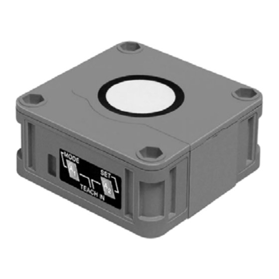
Abmessungen
15
7,5
Folientastatur
LED-Fenster
16
10
34
Technische Daten
Allgemeine Daten
Erfassungsbereich
200 ... 4000 mm
Einstellbereich
240 ... 4000 mm
Blindzone
0 ... 200 mm
Normmessplatte
100 mm x 100 mm
Wandlerfrequenz
ca. 85 kHz
Ansprechverzug
ca. 325 ms
Anzeigen/Bedienelemente
LED grün
permanent grün: Power on
LED gelb 1
permanent: Schaltzustand Schaltausgang 1
blinkend: Lernfunktion
LED gelb 2
permanent: Schaltzustand Schaltausgang 2
blinkend: Lernfunktion
LED rot
Normalbetrieb: "Störung"
Lernfunktion: kein Objekt erkannt
Elektrische Daten
Betriebsspannung
10 ... 30 V DC , Welligkeit 10 %
≤ 60 mA
Leerlaufstrom
I
0
Ein-/Ausgang
Synchronisation
bidirektional
0-Pegel: -U
1-Pegel: +4 V...+U
Eingangsimpedanz: > 12 KΩ
Synchronisationsimpuls: ≥ 100 µs, Synchronisationsimpulspause: ≥ 2 ms
Synchronisationsfrequenz
≤ 13 Hz
Gleichtaktbetrieb
≤ 13/n Hz, n = Anzahl der Sensoren
Multiplexbetrieb
Ausgang
Ausgangstyp
2 Schaltausgänge pnp, Schließer/Öffner wählbar
Voreinstellung
Schaltpunkt A1: 240 mm , Schaltpunkt A2: 4000 mm , breite Ultraschallkeule
≤ 0,5 % vom Schaltpunkt
Reproduzierbarkeit
Bemessungsbetriebsstrom
I
200 mA , kurzschluss-/überlastfest
e
≤ 2,5 V
Spannungsfall
U
d
≤ 1,2 Hz
Schaltfrequenz
f
Abstandshysterese
H
1 % des eingestellten Schaltabstandes
Temperatureinfluss
± 1 % des Endwertes
Normenkonformität
Normen
EN 60947-5-2
Umgebungsbedingungen
Umgebungstemperatur
-25 ... 70 °C (248 ... 343 K)
Lagertemperatur
-40 ... 85 °C (233 ... 358 K)
Mechanische Daten
Schutzart
IP65
Anschluss
Gerätestecker V15 (M12 x 1), 5-polig
Material
Gehäuse
ABS
Wandler
Epoxidharz/Glashohlkugelgemisch; Schaum Polyurethan, Deckel PBT
Masse
150 g
Elektrischer Anschluss Kurven/Zusätzliche Informationen
Normsymbol/Anschluss:
Charakteristische Ansprechkurve
(Version E6, pnp)
1
(BN)
+ U
B
5
(GY)
Sync.
Abstand Y [m]
U
2
(BK)
4
Schaltausgang 1
ebene Platte 100 mm x 100 mm
1,5
2
(WH)
Schaltausgang 2
1
3
(BU)
- U
B
0,5
Adernfarben gemäß EN 60947-5-2.
0
-0,5
-1
-1,5
Rundstab, Ø 25 mm
Steckverbinder V15
-2
2
0
1
3
1
5
4
Zubehör
Montagehilfen
MH 04-3505
MHW 11
*)
Kabeldosen
V15-G-2M-PVC
V15-W-2M-PUR
*)
Weitere Kabeldosen finden Sie im
Abschnitt „Zubehör".
DOWNLOADED FROM WWW.SCATTS.CO.UK
Dimensions
5,2
30
Membrane keys
LED window
65
80
-
S S
...+1 V
B
B
Programmierung der Schaltausgänge
Blindzone
Betriebsart 1:
Ausgang 1
Ausgang 2
Betriebsart 2:
Ausgang 1
Ausgang 2
Betriebsart 3:
Ausgang 1
Ausgang 2
A1
, A2
2
3
4
5
6
heit. Beide Ausgänge verhalten sich gemäß eingestellter
Abstand X [m]
Betriebsart, wenn sich ein Objekt innerhalb des
Erfassungsbereichs befindet.
Y
X
Fenster und Schaltausgang:
breite Schallkeule
schmale Schallkeule
Ausgang 1
Ausgang 1
Ausgang 2
Ausgang 2
Hinweis:
bedeutet: bedecken Sie beim Einlernen dieses
Schaltpunktes die Sensorfläche mit der Hand.
Wenn A1 = A2, arbeiten die Ausgänge so, als wäre A1 < A2
DOWNLOADED FROM WWW.SCATTS.CO.UK
5.2
15
7.5
16
10
34
Technical data
General specifications
Sensing range
Adjustment range
Unusable area
Standard target plate
Transducer frequency
Response delay
Indicators/operating means
LED green
LED yellow 1
LED yellow 2
LED red
Electrical specifications
Operating voltage
No-load supply current
Input/output
Synchronisation
Synchronisation frequency
Common mode operation
Multiplex operation
Output
Output type
Default setting
Repeat accuracy
Rated operational current
Voltage drop
Switching frequency
Range hysteresis
Temperature influence
Standard conformity
Standards
Ambient conditions
Ambient temperature
Storage temperature
Mechanical specifications
Protection degree
Connection
Material
Housing
Transducer
Mass
Electrical connection
Standard symbol/Connections:
(version E6, pnp)
1
(BN)
+ U
5
(GY)
Sync.
U
(BK)
4
Objektabstand
Switch output 1
2
(WH)
Switch output 2
3
(BU)
A1
- U
A2
Core colours in accordance with EN 60947-5-2.
A1
A2
A1
A2
Connector V15
: Detektion auf Objektanwesen-
2
3
1
5
4
A1
A2
A2
A1
Prog. mit Taste A1
A3
Prog. mit Taste A2
A3
Accessories
Mounting aids
MH 04-3505
MHW 11
*)
Cable sockets
V15-G-2M-PVC
V15-W-2M-PUR
*)
For additional cable sockets see section
„Accessories".
Ultraschall-Sensor
Ultrasonic sensor
UB4000-F42-E6-V15
30
65
80
200 ... 4000 mm
240 ... 4000 mm
0 ... 200 mm
100 mm x 100 mm
approx. 85 kHz
approx. 325 ms
permanently green: Power on
permanent: switching state switch output 1
flashing: TEACH-IN function
permanent: switching state switch output 2
flashing: TEACH-IN function
normal operation: "fault"
TEACH-IN function: no object detected
10 ... 30 V DC , ripple 10 %
SS
≤ 60 mA
I
0
bi-directional
0 level -U
...+1 V
B
1 level: +4 V...+U
B
input impedance: > 12 KOhm
synchronisation pulse: ≥ 100 µs, synchronisation interpulse period: ≥ 2 ms
≤ 13 Hz
≤ 13/n Hz, n = number of sensors
2 switch outputs pnp, normally open/close selectable
Switch point A1: 240 mm , Switch point A2: 4000 mm , wide sound lobe
≤ 0.5 % of switching point
I
200 mA , short-circuit/overload protected
e
≤ 2.5 V
U
d
≤ 1.2 Hz
f
H
1 % of the set operating distance
± 1 % of full-scale value
EN 60947-5-2
-25 ... 70 °C (248 ... 343 K)
-40 ... 85 °C (233 ... 358 K)
IP65
connector V15 (M12 x 1), 5 pin
ABS
epoxy resin/hollow glass sphere mixture; foam polyurethane, cover PBT
150 g
Curves/additional information
Characteristic response curve
B
Distance Y [m]
2
Flat surface 100 mm x 100 mm
1.5
1
B
0.5
0
-0.5
-1
-1.5
Round bar, Ø 25 mm
-2
0
1
2
3
4
5
6
Distance X [m]
Y
X
wide sonic beam
narrow sonic beam
Switching output programmation
Unusable area
Object distance
Mode 1:
A1
output 1
output 2
A2
Mode 2:
A1
output 1
output 2
A2
Mode 3:
A1
output 1
output 2
A2
A1
, A2
: Object presence detection.
Both outputs operate according to the selected mode,
if an object is located within the detection range.
Window and Switching point:
output 1
A1
A2
output 1
A2
A1
prog. with A1 key
output 2
A3
output 2
prog. with A2 key
A3
Note:
means: cover transducer surface with your hand,
while programming the output.
If A1 = A2, the output work like A1 < A2
Werbung

Verwandte Anleitungen für Pepperl+Fuchs UB4000-F42-E6-V15


Inhaltszusammenfassung für Pepperl+Fuchs UB4000-F42-E6-V15
- Seite 1 DOWNLOADED FROM WWW.SCATTS.CO.UK Ultraschall-Sensor Abmessungen Dimensions Ultrasonic sensor UB4000-F42-E6-V15 Folientastatur Membrane keys LED-Fenster LED window Technische Daten Technical data General specifications Allgemeine Daten Sensing range 200 ... 4000 mm Erfassungsbereich 200 ... 4000 mm Adjustment range 240 ... 4000 mm Einstellbereich 240 ...
- Seite 2 Pepperl+Fuchs Inc., 1600 Enterprise Parkway, Twinsburg, Ohio 44087, Cleveland-USA, Tel. (330) 4 25 35 55, Telefax (330) 4 25 93 85, sales@us.pepperl-fuchs.com France: Pepperl+Fuchs SARL, 12 Avenue des Tropiques - Les Ulis, 91955 COURTABOEUF CEDEX, Tel. (1) 60 92 13 13, Telefax (1) 60 92 13 25, commercial@fr.pepperl-fuchs.com España Pepperl+Fuchs S.A., Txori-Erri Etorbidea 46, Pol.
- Seite 3 At Scattergood & Johnson Ltd, we pride ourselves on being a technical distributor to specialist industries. Working with a range of quality product suppliers across a number of specialist markets, we are not your average ‘box shifter’ - we are your technical and supply chain partner. We fully support every product we sell - for free! Our internal team and external sales engineers can answer any product or application question, no matter the complexity.